
Related Manuals for Allied Vision Mako


Summary of Contents for Allied Vision Mako
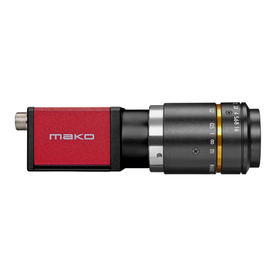
- Page 1 GigE V ISION AMERAS Mako User Guide V4.7.2 FW Loader 40118 Note: Lenses are not part of this product. Allied Vision Technologies GmbH // Taschenweg 2a, 07646 Stadtroda, Germany 2024-Jul-16...
- Page 2 The threads of the lens mount can have sharp edges. Intended use Intended use of Allied Vision product is the integration into vision systems by professionals. All Allied Vision product is sold in a B2B setting. Mako User Guide V4.7.2...
- Page 3 Fare for snitsår på linsemodulets skarpe kanter Linsemodulets gevind kan have skarpe kanter. Tilsigtet brug Allied Vision produktets tilsigtede brug er en indbygning i et visionssystem, udført af fagfolk. Alle Allied Vision produkter sælges i B2B. Mako User Guide V4.7.2...
- Page 4 Eine fallende Kamera oder ein fallendes Objektiv kann Verletzungen verursachen. VORSICHT Schnitte durch scharfkantige Objektivgewinde Objektivgewinde können scharfe Kanten haben. Bestimmungsgemäßer Gebrauch Allied Vision Produkte sind bestimmt für die Integration in Bildverarbeitungs- systeme durch Fachpersonal. Alle Allied Vision Produkte werden in einer B2B-Umgebung verkauft. Mako User Guide V4.7.2...
- Page 5 Las roscas de los objetivos pueden tener bordes afilados. Uso previsto El uso previsto del producto Allied Vision es la integración en el sistema de visión por parte de profesionales. Todos los productos Allied Vision se venden dentro de una relación B2B.
- Page 6 Putoava kamera tai linssi voi aiheuttaa vammoja. HUOMIO Linssien kiinnikkeiden terävien reunojen aiheuttamien viiltovammojen vaara Linssin kiinnikkeiden kierteiden reunat voivat olla teräviä. Käyttötarkoitus Allied Vision -tuotteen käyttötarkoitus on integrointi kuvajärjestelmiin ammattilaisten toimesta. Kaikki Allied Vision -tuotteet myydään B2B-ympäristössä. Mako User Guide V4.7.2...
- Page 7 Les filetages des montures d’objectif peuvent présenter des bords tranchants. Utilisation prévue L’utilisation prévue du produit Allied Vision est son intégration dans des systèmes de vision par le soin de professionnels. Tout produit Allied Vision est vendu dans un cadre B2B. Mako User Guide V4.7.2...
- Page 8 ע ו י מ AlliedVision י ר צ ו מ ת ב י ב ס ב ש ו מ י ש ל ם י ר כ מ נ AlliedVision י ר צ ו מ ל כ Mako User Guide V4.7.2...
- Page 9 Pericolo di tagliarsi sui bordi affilati degli attacchi della lente I bordi della filettatura dell’attacco della lente possono essere affilati. Uso previsto Il prodotto Allied Vision è concepito per essere integrato in sistemi di monitoraggio in campo professionale. Tutti i prodotti Allied Vision sono venduti in uno scenario B2B.
- Page 10 Read before use JA - 日本語 安全性 本カメラを使用する前に、この安全の手引きをお読みください。常に、 警告事項を守ってください。必ず、Intended use 37 ページの通りに、本カ メラを使用してください。 注意 やけどの危険性 作動中のカメラは、やけどを引き起こす温度まで熱くなる恐れがありま す。 注意 カメラまたはレンズの落下によるけが カメラまたはレンズが落下すると、けがをする恐れがあります。 注意 レンズマウントの鋭利な端部で切り傷の危険性 レンズマウントのギザギザの部分が鋭利である可能性があります。 用途 Allied Vision製品は、専門家が視覚装置に統合することを意図したもの です。すべてのAllied Vision製品は、企業間取り引き用に販売されてい ます。 Mako User Guide V4.7.2...
- Page 11 Risico van snijwonden door scherpe randen van lensbevestigingen Het schroefdraad van de lensbevestiging kan scherpe randen hebben. Beoogd gebruik Het beoogde gebruik van het Allied Vision-product is de integratie in optische systemen door professionals. Alle Allied Vision-producten worden verkocht in de B2B-markt.
- Page 12 Risiko for kutt fra skarpe kanter på linsefester Sporene på linsefestet kan ha skarpe kanter. Tiltenkt bruk Den tiltenkte bruken av Allied Vision-produktet er integrering i visjonssystemer av profesjonelle. Alle Allied Vision-produkter selges i en forretning til forretning-situasjon. Mako User Guide V4.7.2...
- Page 13 VARNING Risk för skärsår från vassa kanter på objektivfattningar Objektivets gängor kan ha vassa kanter. Avsedd användning Den avsedda användningen av Allied Vision-produkter är integrering i visionssystem av fackmän. Samtliga Allied Vision-produkter säljs i en B2B-miljö. Mako User Guide V4.7.2...
- Page 14 Read before use ZH - 简体中文版 安全需知 使用本相机前,请阅读本安全说明书。请务必遵守相关警告 和 Intended use 于第 37 页 . 注意事项 烫伤风险 相机操作过程中温度可能上升并导致烫伤风险。 注意事项 相机或者镜头跌落造成伤害 相机或者镜头可能会跌落并造成伤害。 注意事项 镜头接口的锐利边缘划伤风险 镜头接口螺纹边缘可能较为锐利。 预期用途 Allied Vision 产品的预期用途是由专业人士整合到视觉系统中。所有 Allied Vision 的产品均通过 B2B 渠道销售。 Mako User Guide V4.7.2...
- Page 15 Mako cameras at a glance Get an overview of Mako camera documentation. Mako User Guide V4.7.2...
- Page 16 Mako models incorporate high quality CCD or CMOS sensors from Sony, ON Semi, Teledyne e2v, and CMOSIS/ams. Mako cameras are offered with either a C-Mount or CS-Mount to support a wide range of lenses. An M12-Mount )S-Mount( adapter is also available.
- Page 17 Exton, PA 19341, USA Toll-free// +1-877-USA-1394 T// +1 978 225 2030 Asia-Pacific China Japan Allied Vision Technologies Shanghai Co Ltd. Allied Vision Technologies B-510, Venture International Business Park Yokohama Portside Bldg. 10F 2679 Hechuan Road 8-1 Sakae-cho, Kanagawa-ku Minhang District, Shanghai 201103...
- Page 18 ZH - 简体中文版 ............... . 14 Mako cameras at a glance Scope of delivery .
-
Page 19: Table Of Contents
Spectral response ..............80 Mako User Guide V4.7.2... - Page 20 Mako G-032........
- Page 21 Allied Vision software ........
- Page 22 Mako G-223 and G-419 ............. . . 151 Mako G-040, G-158, G-234, G-319, G-507, G-508B POL, G-511, G-811, and G-1242 ... . . 152 Color interpolation )Bayer demosaicing(.
- Page 23 Document history and conventions This chapter includes: Document history ..............24 Manual conventions.............. 30 Mako User Guide V4.7.2...
- Page 24 V4.6.1 2022-Oct-20 • Added firmware versions for better orientation. • Updated values for exposure times and increments in Specifications page 42 onwards for Mako G-040, G-158, G-234, G-319, G-507, G-508 models. • Applied editorial changes. Release: Firmware loader: 39784 V4.6.0 2022-Aug-22 •...
- Page 25 V4.5.0 2021-Sep-16 • Updated Mounting the camera on page 126. • Added data for new Mako G-511, G-811, and G-1242 models to Specifications on page 42 and Focal length vs. field of view on page 115. • Corrected availability for binning with color models for Mako G-507 page 86.
- Page 26 )firmware version 01.54.20343(, see the GigE Firmware Release Notes for details of the changes. • Added trigger latency and trigger jitter values for Mako G-223 and G-419 • Corrected Mako G-040 streamhold capacity value. • Added content to installation chapter: Powering the camera via PoE •...
- Page 27 Allied Vision I/O cable data sheet. V4.3.0 2017-Mar-13 • Added Piecewise Linear HDR option to Exposure Mode for the Mako G-223 and G-419. For more information, see the GigE Features Reference. • Applied various minor corrections.
- Page 28 Specifications, absolute QE, spectral response, ROI frame rate information, camera lens information, and image data flow. • Removed references to Mako G-050 and G-095. The last time shipment period ends on December 31, 2015 as detailed in PCN 2015-05-03. • Updated Camera Interfaces chapter.
- Page 29 2014-Oct-07 • Updated and rearranged Notes on specifications section. • Added Camera features comparison. • Added trigger latency and jitter values for Mako G-032 and G-125. • Updated Mako standard housing drawing. • Updated Mako G-503C section. • Added camera lens information.
- Page 30 • Updated block diagrams in Image data flow chapter. • Updated the Index. V2.0.2 2013-Sep-16 • Updated the frame rate information for Mako G-223 and G-419 in the Specifications chapter. • Updated introduction to include link to Mako documentation webpage. • Updated Status LEDs section.
- Page 31 Material damage by electrostatic discharge (ESD) Precautions as described. Avoiding malfunctions Precautions are described. Practical tip Additional information helps to understand or ease handling the camera. Additional information Web address or reference to an external source with more information is shown. Mako User Guide V4.7.2...
- Page 32 Horizontal × Vertical )sensor resolution measurement( Look-up table MSDS Material Safety Data Sheet Network interface card Near-Infrared Power over Ethernet Quantum efficiency RoHS Restriction of Hazardous Substances Directive Table 5: Acronyms and terms used in this manual (sheet 1 of 2) Mako User Guide V4.7.2...
- Page 33 Document history and conventions Acronym or term Description Region of interest Software Development Kit SFNC Standard Feature Naming Convention Propagation delay high-to-low pdHL Table 5: Acronyms and terms used in this manual (sheet 2 of 2) Mako User Guide V4.7.2...
- Page 34 Compliance, safety, and intended use § This chapter includes: Compliance notifications ............35 Intended use ................. 37 Copyright and trademarks ............ 37 Your safety................38 Product safety ............... 40 Mako User Guide V4.7.2...
-
Page 35: Compliance Notifications
Supplier Declaration of Conformity Mako cameras comply with Part 15 of the FCC Rules. Operation is subject to the following two conditions: 1. This device may not cause harmful interference, and 2. - Page 36 Cet appareil est conforme aux normes classe B pour bruits radioélectriques, spécifiées dans le Règlement sur le brouillage radioélectrique. CAN ICES-3 )B( / NMB-3 )B( Avoid electromagnetic interferences For all power and interface connections, only use shielded cables or cables recommended by Allied Vision. Mako User Guide V4.7.2...
-
Page 37: Intended Use
We are offering standard products as well as customized solutions. Intended use of Allied Vision product is the integration into Vision systems by professionals. All Allied Vision product is sold in a B2B setting. -
Page 38: Your Safety
Your safety This section informs about issues related to your personal safety. Descriptions explain how to avoid hazards and operate Mako cameras safely. Handling lens mounts The lens mount thread has sharp edges. Be careful these edges do not cut your skin when mounting or unmounting lenses. - Page 39 Compliance, safety, and intended use Camera mounting Mako cameras must be mounted using the mounting threads. If vibration is higher than specified, cameras can disconnect from the mounting. Falling cameras can hurt you. To avoid personal injury: • Mount the camera according to the instructions in the installation chapter.
-
Page 40: Product Safety
• Only use power supplies that meet the insulation requirement according to PELV or SELV. For details, please refer to IEC 61140. • If using external power supplies by third-party manufacturers, observe polarity to avoid damage to the camera electronics. Mako User Guide V4.7.2... - Page 41 Sensors are sensitive to excessive radiation: focused sunlight, UV light, lasers, and X-rays can damage the sensor. Dirt and scratches can damage the sensor as well. Mako cameras do not need additional cleaning. Cameras are cleaned before shipping. Incorrect cleaning can damage the sensor or the filter. Therefore, never clean the sensor or the filter.
- Page 42 Specification tables, quantum efficiency plots, and ROI frame rates for each model, starting with Mako G-032................48 Camera feature availability ..........106 Mechanical dimensions ............108 Sensor position accuracy ............ 110 Lens protrusion for different mounts ......... 111 Mako User Guide V4.7.2...
-
Page 43: Applied Standards
The GenICam standard consists of multiple modules that specify tasks to be solved. Allied Vision cameras and software make use of these modules, like the SFNC that standardizes feature names and types via an XML file or the transport layer interface )GenTL( that is used to grab images. -
Page 44: Notes On Specifications
The dimensions listed in the following tables are for Mako standard housing models. Dimensions include the default lens mount and connectors but not the tripod and lens. The mass listed in the following table are for Mako models only and does not include the tripod and lens. Frame memory Normally, an image is captured and transported in consecutive steps. -
Page 45: Absolute Qe Plots
• All measurements were done without optical filters. With optical filters, QE decreases by approximately 10 percent. • QE measurements for the Mako G-508B POL )IMX250MRZ( were measured with unpolarized light. • The uncertainty in measurement of the QE values is 10 percent. This is mainly due to uncertainties in the measuring apparatus itself )Ulbricht sphere, optometer(. -
Page 46: Spectral Response Plots
448 nm, 529 nm, and 632 nm. The shape of the curve is taken from the sensor data sheet but the values have been adjusted based on these measured values. The uncertainty in measurement of the spectral response values is 10 percent. Mako User Guide V4.7.2... -
Page 47: Specifications Common To All Models
Specifications Specifications common to all models The following table provides specifications common to all Mako models. Feature Specification Default lens mount C-Mount Default optical filter • Monochrome and NIR models: No filter • Color models: Type Hoya C-5000 IR cut filter... -
Page 48: Mako G-032
Specifications Mako G-032 The following tables provide model specifications. The values are valid for the corresponding Mako G-032B and G-032C models. For specifications common to all models, see Specifications common to all models. Specification Feature Mako G-032B Mako G-032C Sensor model... -
Page 49: Mako G-032
Specifications Absolute QE Figure 2: Mako G-032 (Sony ICX424) absolute QE Spectral response Figure 3: Mako G-032 (Sony ICX424) spectral response Mako User Guide V4.7.2... -
Page 50: Roi Frame Rate
492 ROI height 195.81 µs Maximum frame rate at full resolution according to formula: 102.3 fps Width = 658 pixels Height [pixels] Figure 4: Mako G-032 frame rate as a function of ROI height Height Frame rate (fps) Height Frame rate (fps) 102.3... -
Page 51: Mako G-040
Specifications Mako G-040 The following table provides model specifications. The values are valid for Mako G-040B and G-040C models. For specifications common to all models, see Specifications common to all models. Specification Feature Mako G-040B Mako G-040C Sensor model Sony IMX287LLR Exmor Sony IMX287LQR Exmor Resolution )H ×... - Page 52 RGB8Packed, BGR8Packed, 217 μs YUV444Packed These values are calculated directly from the microcontroller source. There is no differentiation between Idle and Frame valid states for this sensor. Table 9: Mako G-040 model specifications (sheet 2 of 2) Mako User Guide V4.7.2...
-
Page 53: Absolute Qe
Specifications Absolute QE Blue QE Green QE Red QE Monochrome QE Sony IMX287 absolute QE 1000 Wavelength [nm] Figure 5: Mako G-040 (Sony IMX287) absolute QE Spectral response Figure 6: Mako G-040 (Sony IMX287) spectral response Mako User Guide V4.7.2... - Page 54 ROI frame rate 3700 Width=728 pixels 3330 2960 2590 2220 1850 1480 1110 Height [pixels] Figure 7: Mako G-040 frame rate as a function of ROI height Height Frame rate (fps) Height Frame rate (fps) 286.0 1685.5 328.2 2091.6 420.4 2755.6 778.5...
- Page 55 Specifications Mako G-125 The following table provides model specifications. The values are valid for Mako G-125B and G-125C models. For specifications common to all models, see Specifications common to all models. Specification Feature Mako G-125B Mako G-125C Sensor model Sony ICX445ALA Sony ICX445AQA Resolution )H ×...
- Page 56 Absolute QE Blue QE Green QE Red QE Monochrome QE Sony ICX445 absolute QE 1000 Wavelength [nm] Figure 8: Mako G-125 (Sony ICX445) absolute QE Spectral response Blue Response Green Response Red Response Monochrome Response 0.3000 Sony ICX445 spectral response 0.2000...
-
Page 57: Roi Frame Rate
964 ROI height 176.42 µs Maximum frame rate at full resolution according to formula: 30.3 fps Width=1292 pixels 1000 Height [pixels] Figure 10: Mako G-125 frame rate as a function of ROI height Height Frame rate (fps) Height Frame rate (fps) 30.3 94.4... - Page 58 Specifications Mako G-131 The following table provides model specifications. The values are valid for Mako G-131B and G-131C models. For specifications common to all models, see Specifications common to all models. Specification Feature Mako G-131B Mako G-131C Sensor model Teledyne e2v EV76C560 Resolution )H ×...
- Page 59 Mono8, BayerBG8, 24 µs YUV411Packed Mako G-131 supports BinningHorizontalMode = Sum or Average and BinningVerticalMode = Sum or Average. These values are calculated directly from the microcontroller source. These values are only valid for pixel formats < 16 bits per pixel and applicable in both Idle and Frame valid states: •...
-
Page 60: Absolute Qe
Blue QE Green QE Red QE Monochrome QE Teledyne e2v EV76C560 absolute QE 1000 Wavelength [nm] Figure 11: Mako G-131 (Teledyne e2v EV76C560) absolute QE Spectral response Blue Response Green Response Red Response Monochrome Response 0.4000 Teledyne e2v EV76C560 spectral response 0.3000... -
Page 61: Roi Frame Rate
Specifications ROI frame rate 2000 Width=1280 pixels 1050 Height [pixels] Figure 13: Mako G-131 frame rate as a function of ROI height Height Frame rate (fps) Height Frame rate (fps) 1024 62.0 170.0 66.0 249.0 82.0 462.0 87.0 809.0 121.0 1295.0... - Page 62 Specifications Mako G-158 The following table provides model specifications. The values are valid for Mako G-158B and G-158C models. For specifications common to all models, see Specifications common to all models. Specification Feature Mako G-158B Mako G-158C Sensor model Sony IMX273LLR Exmor Sony IMX273LQR Exmor Resolution )H ×...
- Page 63 RGB8Packed, BGR8Packed, 434 μs YUV444Packed These values are calculated directly from the microcontroller source. There is no differentiation between Idle and Frame valid states for this sensor. Table 15: Mako G-158 model specifications (sheet 2 of 2) Mako User Guide V4.7.2...
-
Page 64: Absolute Qe
Absolute QE Blue QE Green QE Red QE Monochrome QE Sony IMX273 absolute QE 1000 Wavelength [nm] Figure 14: Mako G-158 (Sony IMX273) absolute QE Spectral response Blue Response Green Response Red Response Monochrome Response 0.4000 Sony IMX273 spectral response 0.3000... -
Page 65: Roi Frame Rate
ROI frame rate 1900 Width=1456 pixels 1710 1520 1330 1140 1000 1100 Height [pixels] Figure 16: Mako G-158 frame rate as a function of ROI height Height Frame rate (fps) Height Frame rate (fps) 1088 75.2 220.5 1080 75.6 400.4 1024 79.6... - Page 66 Specifications Mako G-192 The following table provides model specifications. The values are valid for Mako G-192B and G-192C models. For specifications common to all models, see Specifications common to all models. Specification Feature Mako G-192B Mako G-192C Sensor model Teledyne e2v EV76C570 Resolution )H ×...
- Page 67 Time between exposures Mono8, BayerBG8, YUV411Packed 34 µs Mako G-192 supports BinningHorizontalMode = Sum or Average and BinningVerticalMode = Sum or Average. These values are calculated directly from the microcontroller source. These values are only valid for pixel formats <...
-
Page 68: Absolute Qe
Blue QE Green QE Red QE Monochrome QE Teledyne e2v EV76C570 absolute QE 1000 Wavelength [nm] Figure 17: Mako G-192 (Teledyne e2v EV76C570) absolute QE Spectral response Figure 18: Mako G-192 (Teledyne e2v EV76C570) absolute QE Mako User Guide V4.7.2... -
Page 69: Roi Frame Rate
Specifications ROI frame rate 2000 Width=1600 pixels 1000 1200 Height [pixels] Figure 19: Mako G-192 frame rate as a function of ROI height Height Frame rate (fps) Height Frame rate (fps) 1200 60.0 193.0 1024 70.0 282.0 75.0 525.0 93.0 919.0... - Page 70 Specifications Mako G-223 The following table provides model specifications. The values are valid for Mako G-223B and G-223C models. For specifications common to all models, see Specifications common to all models. Specification Feature Mako G-223B Mako G-223C Sensor model CMOSIS/ams CMV2000 with microlens Resolution )H ×...
-
Page 71: Absolute Qe
Specifications Absolute QE Green Blue Monochrome CMOSIS/AMS CMV2000, CMV4000 absolute QE 1000 1100 Wavelength [nm] Figure 20: Mako G-223 (CMOSIS/ams CMV2000) absolute QE Spectral response Green Blue Monochrome 0.400 CMOSIS/AMS CMV2000, CMV4000 spectral response 0.350 0.300 0.250 0.200 0.150 0.100 0.050... -
Page 72: Roi Frame Rate
Specifications ROI frame rate 5000 Width=2048 pixels 1000 1100 Height [pixels] Figure 22: Mako G-223 frame rate as a function of ROI height Height Frame rate (fps) Height Frame rate (fps) 1088 49.5 260.8 1000 53.8 502.1 59.7 934.6 67.1 1933.8... - Page 73 Specifications Mako G-234 The following table provides model specifications. The values are valid for Mako G-234B and G-234C models. For specifications common to all models, see Specifications common to all models. Specification Feature Mako G-234B Mako G-234C Sensor model Sony IMX249LLJ Exmor Sony IMX249LQJ Exmor Resolution )H ×...
- Page 74 These values are calculated directly from the microcontroller source. There is no differentiation between Idle and Frame valid states for this sensor. Table 21: Mako G-234 model specifications (sheet 2 of 2) With 10-bit sensor readout mode you can achieve a higher frame rate. The sensor is capable of higher frame rates but readout is limited by GigE bandwidth and exposure value.
-
Page 75: Absolute Qe
Specifications Absolute QE Figure 23: Mako G-234 (Sony IMX249) absolute QE Spectral response Figure 24: Mako G-234 (Sony IMX249) spectral response Mako User Guide V4.7.2... -
Page 76: Roi Frame Rate
12-bit sensor readout 1000 Width=1936 pixels 12 bit sensor readout 1000 1125 1250 Height [pixels] Figure 25: Mako G-234 12-bit sensor frame rate as a function of ROI height Height Frame rate (fps) Height Frame rate (fps) 1216 32.3 169.8 1080 36.3... - Page 77 1300 Width=1936 pixels 1170 10 bit sensor readout 1040 1000 1125 1250 Height [pixels] Figure 26: Mako G-234 10-bit sensor frame rate as a function of ROI height Height Frame rate (fps) Height Frame rate (fps) 1216 41.5 217.9 1080 46.5...
- Page 78 Specifications Mako G-319 The following table provides model specifications. The values are valid for Mako G-319B and G-319C models. For specifications common to all models, see Specifications common to all models. Specification Feature Mako G-319B Mako G-319C Sensor model Sony IMX265LLR Exmor Sony IMX265LQR Exmor Resolution )H ×...
- Page 79 RGB8Packed, BGR8Packed, 467 μs YUV444Packed These values are calculated directly from the microcontroller source. There is no differentiation between Idle and Frame valid states for this sensor. Table 24: Mako G-319 model specifications (sheet 2 of 2) Mako User Guide V4.7.2...
-
Page 80: Absolute Qe
Absolute QE Blue QE Green QE Red QE Monochrome QE Sony IMX265 absolute QE 1000 Wavelength [nm] Figure 27: Mako G-319 (Sony IMX265) absolute QE Spectral response Blue Response Green Response Red Response Monochrome Response 0.4000 Sony IMX265 spectral response 0.3000... -
Page 81: Roi Frame Rate
Width=2064 pixels 1600 1400 1200 1000 1040 1170 1300 1430 1560 Height [pixels] Figure 29: Mako G-319 frame rate as a function of ROI height Height Frame rate (fps) Height Frame rate (fps) 1544 37.6 187.7 1280 45.2 408.5 1024 56.5... -
Page 82: Mako G-319
Specifications Mako G-419 The following table provides model specifications. The values are valid for Mako G-419B, G-419B NIR, and G-419C models. For specifications common to all models, Specifications common to all models. Specification Feature Mako G-419B, G-419B NIR Mako G-419C... -
Page 83: Absolute Qe
CMOSIS/AMS CMV2000, CMV4000 absolute QE 1000 1100 Wavelength [nm] Figure 30: Mako G-419 (CMOSIS/ams CMV4000) absolute QE Monochrome CMOSIS/AMS CMV2000-NIR, CMV4000-NIR absolute QE 1000 1100 Wavelength [nm] Figure 31: Mako G-419B NIR (CMOSIS/ams CMV4000) absolute QE Mako User Guide V4.7.2... -
Page 84: Spectral Response
0.200 0.150 0.100 0.050 0.000 1000 1100 Wavelength [nm] Figure 32: Mako G-419 (CMOSIS/ams CMV4000) spectral response Monochrome CMOSIS/AMS CMV2000-NIR, CMV4000-NIR spectral response 1000 1100 Wavelength [nm] Figure 33: Mako G-419B NIR (CMOSIS/ams CMV4000) spectral response Mako User Guide V4.7.2... - Page 85 Specifications ROI frame rate 5000 Width=2048 pixels 1200 1500 1800 2100 Height [pixels] Figure 34: Mako G-419 frame rate as a function of ROI height Height Frame rate (fps) Height Frame rate (fps) 2048 26.3 132.1 2000 26.9 257.7 1800 29.9...
- Page 86 Specifications Mako G-507 The following table provides model specifications. The values are valid for Mako G-507B and G-507C models. For specifications common to all models, see Specifications common to all models. Specification Feature Mako G-507B Mako G-507C Sensor model Sony IMX264LLR Exmor Sony IMX264LQR Exmor Resolution )H ×...
- Page 87 RGB8Packed, BGR8Packed, 554 μs YUV444Packed These values are calculated directly from the microcontroller source. There is no differentiation between Idle and Frame valid states for this sensor. Table 28: Mako G-507 model specifications (sheet 2 of 2) Mako User Guide V4.7.2...
- Page 88 Absolute QE Blue QE Green QE Red QE Monochrome QE Sony IMX264 absolute QE 1000 Wavelength [nm] Figure 35: Mako G-507 (Sony IMX264) absolute QE Spectral response Blue Response Green Response Red Response Monochrome Response 0.4000 Sony IMX264 spectral response 0.3000...
- Page 89 ROI frame rate 1440 Width=2464 pixels 1320 1200 1080 1200 1500 1800 2100 Height [pixels] Figure 37: Mako G-507 frame rate as a function of ROI height Height Frame rate (fps) Height Frame rate (fps) 2056 23.7 100.3 1544 31.5 133.0 1324 36.8...
- Page 90 Specifications Mako G-508B POL The following table provides model specifications for Mako G-508B POL. For specifications common to all models, see Specifications common to all models. Feature Specification Sensor model Sony IMX250MZR Polarsens Resolution )H × V( 2464 × 2056; 5.0 MP...
- Page 91 Absolute QE Mono hrom QE Son IMX250MZR t QE ngth [nm] Figure 38: Mako G-508B POL (Sony IMX250MZR) absolute QE Relative spectral response Wa ele gth Figure 39: Mako G-508B POL (Sony IMX250MZR) relative spectral response Mako User Guide V4.7.2...
- Page 92 The 90 degree signal and 45 degree signal lines, and the 135 degree signal and 0 degree signal lines are output successively. Polariza on Coding Diagram Figure 40: Polarization coding of physical pixel array Mako User Guide V4.7.2...
- Page 93 ROI frame rate 1440 Width=2464 pixels 1320 1200 1080 1200 1500 1800 2100 Height [pixels] Figure 41: Mako G-508B POL frame rate as a function of ROI height Height Frame rate (fps) Height Frame rate (fps) 2056 23.7 100.3 1544 31.5 133.0 1324 36.8...
- Page 94 Specifications Mako G-511 The following table provides model specifications. The values are valid for Mako G-511B and G-511C models. For specifications common to all models, see Specifications common to all models. Specification Feature Mako G-511B Mako G-511C Sensor model Sony IMX547-AAMJ-C...
- Page 95 RGB8Packed, BGR8Packed, 1372 μs YUV444Packed These values are calculated directly from the microcontroller source. There is no differentiation between Idle and Frame valid states for this sensor. Table 32: Mako G-511 model specifications (sheet 2 of 2) Mako User Guide V4.7.2...
- Page 96 Absolute QE Blue QE Green QE Red QE Monochrome QE Sony IMX54x absolute QE 1000 Wavelength [nm] Figure 42: Mako G-511 (Sony IMX547) absolute QE Spectral response Blue Response Green Response Red Response Monochrome Response 0.4000 Sony IMX54x spectral response 0.3000...
- Page 97 Specifications ROI frame rate Width=2472 pixels 1000 1200 1400 1600 1800 2000 Height [pixels] Figure 44: Mako G-511 frame rate as a function of ROI height Height Frame rate (fps) Height Frame rate (fps) 2064 23.4 165.9 2000 24.1 240.3 1504 31.6...
- Page 98 Specifications Mako G-811 The following table provides model specifications. The values are valid for Mako G-811B and G-811C models. For specifications common to all models, see Specifications common to all models. Specification Feature Mako G-811B Mako G-811C Sensor model Sony IMX546-AAMJ-C...
- Page 99 RGB8Packed, BGR8Packed, 1566 μs YUV444Packed These values are calculated directly from the microcontroller source. There is no differentiation between Idle and Frame valid states for this sensor. Table 34: Mako G-811 model specifications (sheet 2 of 2) Mako User Guide V4.7.2...
- Page 100 Absolute QE Blue QE Green QE Red QE Monochrome QE Sony IMX54x absolute QE 1000 Wavelength [nm] Figure 45: Mako G-811 (Sony IMX546) absolute QE Spectral response Blue Response Green Response Red Response Monochrome Response 0.4000 Sony IMX54x spectral response 0.3000...
- Page 101 ROI frame rate Width=2856 pixels 200 400 600 800 1000 1200 1400 1600 1800 2000 2200 2400 2600 2800 Height [pixels] Figure 47: Mako G-811 frame rate as a function of ROI height Height Frame rate (fps) Height Frame rate (fps) 2848 14.7...
- Page 102 Specifications Mako G-1242 The following table provides model specifications. The values are valid for Mako G-1242B and G-1242C models. For specifications common to all models, see Specifications common to all models. Specification Feature Mako G-1242B Mako G-1242C Sensor model Sony IMX545-AAMJ-C...
- Page 103 RGB8Packed, BGR8Packed, 2238 μs YUV444Packed These values are calculated directly from the microcontroller source. There is no differentiation between Idle and Frame valid states for this sensor. Table 36: Mako G-1242 model specifications (sheet 2 of 2) Mako User Guide V4.7.2...
- Page 104 Absolute QE Blue QE Green QE Red QE Monochrome QE Sony IMX54x absolute QE 1000 Wavelength [nm] Figure 48: Mako G-1242 (Sony IMX545) absolute QE Spectral response Blue Response Green Response Red Response Monochrome Response 0.4000 Sony IMX54x spectral response 0.3000...
- Page 105 ROI frame rate Width=4128 pixels 1200 1500 1800 2100 2400 2700 3000 Height [pixels] Figure 50: Mako G-1242 frame rate as a function of ROI height Height Frame rate (fps) Height Frame rate (fps) 3008 44.5 3000 62.3 2504 11.6 103.8...
-
Page 106: Camera Feature Availability
Specifications Camera feature availability Mako cameras support a number of standard and extended features. The following table identifies a selection of capabilities and compares the availability of features in Mako camera models. A complete listing of camera features, including definitions can be found on the Allied Vision Technical Documentation webpage. - Page 107 ✔ ✔ ✔ ✔ ✔ ✔ ✔ ✔ ✔ ✔ ✔ ✔ ✔ ✔ ✔ User sets Camera control feature availability by model Table 39: Some features are firmware dependent, refer to the GigE Firmware Release Notes for more information. Mako User Guide V4.7.2...
-
Page 108: Mechanical Dimensions
M3 - 2.3 (2x) Figure 51: Mako with C-Mount dimensions (including connectors) CS-Mount Contact Allied Vision support for a technical drawing of the Mako with a CS-Mount. A STEP files is available on the technical documentation webpage. Mako User Guide V4.7.2... - Page 109 Specifications M12-Mount (S-Mount) Contact Allied Vision support for a technical drawing or STEP file of the Mako with a M12-Mount )S-Mount(. Tripod adapter This tripod adapter )Allied Vision order number 4807( can be used for all Mako cameras with the standard housing.
-
Page 110: Sensor Position Accuracy
±150 µm )sensor shift( y-axis 0 µm to -150 µm )optical back focal length( α ± 0.5 degrees )sensor rotation as the deviation from the parallel to the camera bottom( Table 40: Sensor position accuracy criteria Mako User Guide V4.7.2... -
Page 111: Lens Protrusion For Different Mounts
Specifications Lens protrusion for different mounts All standard color Mako cameras are equipped with a Type Hoya C-5000 IR cut filter with a 22 mm diameter. Standard monochrome and NIR Mako cameras are not equipped with any optical filter. We offer several optical filter options for both monochrome, near infrared, and color Mako cameras. - Page 112 Adjustment spacer Figure 55: CS-Mount with 22 mm filter M12-Mount (S-Mount) with 22 mm filter Contact Allied Vision support for an cross section technical drawing of the Mako with a M12-Mount )S-Mount( and 22 mm filter. C-Mount with 16 mm filter Maximum protrusion: 10.2...
- Page 113 Adjustment spacer Figure 57: CS-Mount with 16 mm filter M12-Mount (S-Mount) with 16 mm filter Contact Allied Vision support for an cross section technical drawing of the Mako with an M12-Mount )S-Mount( and 16 mm filter. Dimensional adjustment The dimensional adjustment cannot be done by the customer. All modifications have to be done by Allied Vision.
- Page 114 Filter and lenses This chapter includes: Focal length vs. field of view..........115 Optical filters ............... 123 Mako User Guide V4.7.2...
- Page 115 148 × 109 mm 301 × 221 mm 25 mm 93 × 68 mm 191 × 140 mm 35 mm 65 × 48 mm 135 × 99 mm Table 41: Mako G-032 focal length versus field of view Mako User Guide V4.7.2...
- Page 116 25 mm 95 × 71 mm 195 × 146 mm Table 42: Mako G-040 focal length versus field of view Mako G-131 The following table provides the field of view for various focal lengths. The values are valid for Mako G-131B and G-131C models.
- Page 117 25 mm 95 × 71 mm 195 × 146 mm Table 44: Mako G-158 focal length versus field of view Mako G-192 The following table provides the field of view for various focal lengths. The values are valid for Mako G-192B and G-192C models.
- Page 118 114 × 60 mm A 2/3 inch lens may cause vignetting )1 inch lens recommended( Table 46: Mako G-223 focal length versus field of view Mako G-234 The following table provides the field of view for various focal lengths. The values are valid for Mako G-234B and G-234C models.
- Page 119 75 mm 40 × 30 mm 88 × 65 mm Table 48: Mako G-319 focal length versus field of view Mako G-419 The following table provides the field of view for various focal lengths. The values are valid for Mako G-419B, G-419B NIR, and G-419C models.
- Page 120 113 × 94 mm 234 × 196 mm 50 mm 77 × 64 mm 162 × 135 mm 75 mm 48 × 40 mm 105 × 88 mm Figure 59: Mako G-508B POL focal length versus field of view Mako User Guide V4.7.2...
- Page 121 50 mm 61 × 51 mm 129 × 107 mm Table 50: Mako G-511 focal length versus field of view Mako G-811 The following table provides the field of view for various focal lengths. The values are valid for Mako G-811 models.
- Page 122 150 × 109 mm 312 × 227 mm 50 mm 102 × 74 mm 215 × 157 mm 75 mm 64 × 47 mm 139 × 102 mm Table 52: Mako G-1242 focal length versus field of view Mako User Guide V4.7.2...
- Page 123 Filter and lenses Optical filters All color Mako cameras are equipped with a type Hoya C-5000 IR cut filter. This filter is employed to prevent infrared light from passing to the sensor. In the absence of an IR cut filter, images are dominated by red and incapable of being properly color balanced.
- Page 124 Touching hot cameras ............125 Electrostatic discharge ............125 Mounting the camera ............126 Mounting the lens............... 128 Configuring the host computer .......... 129 Connecting your camera............. 132 Powering up the camera............. 132 Connecting to host application........... 134 Accessories................135 Mako User Guide V4.7.2...
-
Page 125: Touching Hot Cameras
• Wrist strap: Wear a static-dissipative wrist strap to ground your body. • Clothing: Wear ESD-protective clothing. Keep components away from your body and clothing. Even if you are wearing a wrist strap, your body is grounded but your clothes are not. Mako User Guide V4.7.2... -
Page 126: Mounting The Camera
)C( of 2.3 mm between screws and mounting threads. For mounting hole b: Use 0.51 Nm maximum torque for a thread engagement )C( of 2.2 mm between screws and mounting threads. 2. Continue with Mounting the lens on page 128. Mako User Guide V4.7.2... - Page 127 Table 53: Adjusting maximum torque values example To ensure that the screws do not become loose over time, we recommend you to use means for securing screws, such as screw locking varnish. Tripod adapter For more information, see www.alliedvision.com/en/products/accessories/. Mako User Guide V4.7.2...
-
Page 128: Mounting The Lens
Installing the camera NOTICE Avoid damage to the camera by using inappropriate accessories The Mako U tripod adapter is not compatible with Mako cameras. Mounting the lens CAUTION Injury by falling cameras or lenses A falling camera or lens can cause injury. -
Page 129: Configuring The Host Computer
For more information, please contact support at www.alliedvision.com/en/about-us/contact-us/technical-support-repair-/-rma. Configuring the host computer Mako cameras can operate on 10/100 or Gigabit speed NICs. In order to reach the maximum camera frame rate, a Gigabit speed network NIC with jumbo packet support is required. - Page 130 192.168.100.2 255.255.255.0 Blank NIC 2 192.168.101.1 255.255.255.0 Blank Camera 2 connected to NIC 2 192.168.101.2 255.255.255.0 Blank Camera 3 connected to NIC 2 192.168.101.3 255.255.255.0 Blank Table 54: Static IP addresses for NICs and connected cameras Mako User Guide V4.7.2...
- Page 131 256 bytes Table 55: NIC settings Default packet size The default packet size of Mako cameras is 8228 bytes. The host NIC needs to support a packet size of equal or larger size to stream from the camera. NIC settings The NIC settings may also vary depending on your system configuration and the NIC manufacturer.
-
Page 132: Connecting Your Camera
6. Click OK to save the setting. Connecting your camera Use a Category 6 or higher rated Ethernet cable to connect the Mako camera to the NIC. Crossover cabling is not required but does work. The camera has circuitry to determine if a crossover cable is being used. - Page 133 Hirose I/O port only. Powering the camera via PoE Please note the following when using PoE accessories with Allied Vision PoE-capable GigE cameras: • Mako cameras conform to the IEEE 802.3at Type 1 standard for GigE. Mako User Guide V4.7.2...
-
Page 134: Connecting To Host Application
Connecting to host application After you have installed the Vimba Viewer or third-party application to your host computer, connect your Mako camera via an Ethernet cable. If your camera is not PoE powered, connect the Hirose cable to power the camera. -
Page 135: Accessories
62,000,000. Accessories We offer a wide range of accessories for use with Mako cameras including: • Gigabit Ethernet accessories, such as standard GigE components or PoE capable GigE components. - Page 136 Camera interfaces This chapter includes: Back panel ................137 Status LEDs ................137 Gigabit Ethernet port ............138 Camera I/O connections ............. 138 Control signals..............143 Camera trigger ..............145 Mako User Guide V4.7.2...
-
Page 137: Back Panel
Figure 63: Rear view of Mako cameras LED 1 )orange( LED 2 )green( Hirose I/O port Gigabit Ethernet port Table 56: Ports and LEDs Status LEDs The following tables describe the Mako status LEDs. LED 1 Status Solid orange Ethernet link established Flashing orange Network traffic... -
Page 138: Gigabit Ethernet Port
Safety-related instructions to avoid malfunctions Read all Notes and Cautions in the Hardware and Installation chapter before using the Hirose I/O connector. Hirose connector The cable side Hirose connector is available for purchase from Allied Vision )order code K7600503(. Mako User Guide V4.7.2... - Page 139 Ground for external power Ground for camera Orange dot power supply Table 59: Camera I/O connector pin assignment and I/O cable color coding For cable color and pin out information, see the Allied Vision I/O cable overview: www.alliedvision.com/fileadmin/content/documents/products/accessories/cable/ datasheet/IO-Cable_Overview_DataSheet.pdf. Mako User Guide V4.7.2...
- Page 140 ORANGE DOT BLACK ORANGE DOT RED SHIELD TRANSPARENT Hirose HR25 Open End Figure 64: Mako cable color coding Input block diagram External Internal 180R Isolated In GND Figure 65: Input block diagram The input can be connected directly to the system for voltages up to 24 VDC. An external resistor is not necessary.
- Page 141 Current )constant-current source( 3 to 4 mA Table 60: Input parameters Minimum pulse width The minimum pulse width for all Mako cameras is: 20 kHz Figure 66: Minimum pulse width Test conditions The input signal was driven with 3.3 Volts and no external additional series resistor.
- Page 142 Figure 68: Output switching times Parameter and value 1 µs 26 µs 1 µs 21 µs 2 µs 47 µs can deviate by 5 µs( Table 62: Parameters Mako User Guide V4.7.2...
-
Page 143: Control Signals
All input and output signals that pass the I/O connector are controlled by the I/O strobe commands. Input block diagram Polarity selectable via so ware Input signal LP lter Optocoupler Input state Figure 69: Input block diagram Mako User Guide V4.7.2... - Page 144 Table 63: Output signals Output block diagram Output mode selectable via so ware Polarity selectable via so ware Acquisi onTriggerReady FrameTriggerReady Read from so ware FrameTrigger Exposing FrameReadout Output signal Acquiring Optocoupler SyncIn1 Strobe1 Figure 70: Output block diagram Mako User Guide V4.7.2...
-
Page 145: Camera Trigger
Note: Ji er at the beginning Logic trigger of an exposure has no e ect on the length of exposure. Exposure N+ 1 Trigger ji er Readout N+ 1 Trigger ready Imaging Idle Figure 72: Internal signal timing waveforms (CMOS-sensor models) Mako User Guide V4.7.2... - Page 146 High if the camera image sensor is not exposing or reading out data Table 64: Trigger definitions Trigger rules Overlapping exposure and readout (Mako G-131 and G-192) The Teledyne e2v sensor does not support overlapped exposure and readout in hardware trigger mode or in global reset mode.
- Page 147 In this case, trigger latency and trigger jitter can be up to one line time since exposure must always begin on an Interline boundary. For a more detailed description of the trigger concept for advanced users and special scenarios, see the Triggering Concept application note at www.alliedvision.com/en/support/faqs-application-notes. Mako User Guide V4.7.2...
- Page 148 Image data flow This chapter includes: Mako models with CCD sensors.......... 149 Mako models with CMOS sensors ........150 Color interpolation )Bayer demosaicing(......153 Mako User Guide V4.7.2...
- Page 149 For on camera interpolated PixelFormats only (8 bit output). Raw un interpolated PixelFormats skip this block (8/12 bit output) depending upon the bit depth of PixelFormat used. Figure 73: Mako G-032 and G-125 image data flow Mako User Guide V4.7.2...
- Page 150 For on camera interpolated pixel formats only (8 bit output). Raw un interpolated pixel formats skip this block (8/10 bit output) depending upon the bit depth of pixel format used. Figure 74: Mako G-131 and G-192 image data flow Mako User Guide V4.7.2...
- Page 151 For on camera interpolated pixel formats only (8 bit output). Host GigE Raw un interpolated pixel formats skip this block (8/12 bit output) depending upon the bit depth of pixel format used. Figure 75: Mako G-223 and G-419 image data flow Mako User Guide V4.7.2...
- Page 152 Streaming Monochrome cameras and Engine RAW pixel formats GigE Vision MAC BinningY is supported by Mako G 040C, G 158C, and G 234C only GigE Interface Color cameras only GigE Host For on camera interpolated pixel formats only (8 bit output). Raw un interpolated pixel formats skip this block (8/12 bit output) depending upon the bit depth of pixel format used.
- Page 153 Bayer mosaic layout. An effective Bayer to RGB color interpolation already takes place in all Mako color version cameras. In color interpolation a red, green, or blue value is determined for each pixel. A proprietary Bayer demosaicing algorithm is used for this interpolation, optimized for both sharpness of contours as well as reduction of false edge coloring.
- Page 154 This is also a consequence of Bayer demosaicing as the image width displayed on the color camera is not scaled down. • Using a ROI, x and y resolutions must be even-numbered. Mako User Guide V4.7.2...
- Page 155 Cleaning optical components This chapter includes: Keeping optical components clean........156 Identifying impurities............157 Locating impurities.............. 157 Materials for cleaning optical components ......159 Cleaning Instructions ............160 Mako User Guide V4.7.2...
-
Page 156: Keeping Optical Components Clean
Cleaning optical components Read these instructions before you contact Allied Vision or your Allied Vision distribution partner for assistance. Contact Allied Vision or your Allied Vision distribution partner if you are not familiar with the procedures described in this chapter. NOTICE... -
Page 157: Identifying Impurities
Cleaning optical components Identifying impurities If you observe any image artifacts in your video preview of your Mako camera you may have impurities either on the lens, optical filter, or on the sensor surface. Every Mako camera is cleaned prior to sealing and shipment; however, impurities may develop due to handling or unclean environments. - Page 158 Removing the IR cut filter Standard Mako G-507C models with SN ≥ 536883430 and all other standard Mako models with SN ≥ 536884750 are equipped with a 22 mm diameter IR cut filter. Filters can be removed with the E9020001 filter removal tool.
-
Page 159: Materials For Cleaning Optical Components
Optical cleaning liquid material safety data sheets Read the MSDS for the optical cleaning liquid before cleaning your camera or optics. The MSDS provides important information including hazard identification, first aid measures, handling and storage, and PPE. Mako User Guide V4.7.2... -
Page 160: Cleaning Instructions
6. If dust spots remain, repeat this procedure using new clean lens tissue )as previously described(. If you notice that the camera lens or sensor is not clean after attempting to clean twice, or if you have any questions regarding cleaning your camera, contact your Allied Vision distribution partner. Mako User Guide V4.7.2... - Page 161 Cleaning optical components Cleaning with compressed air We do not recommend cleaning Mako cameras with compressed air. Figure 83: Cleaning with compressed air is not recommended NOTICE Possible material damage • Compressed air at high pressure or shorter operating distances may push dust into the camera or lens and physically damage the camera, sensor, or optical components.
- Page 162 Firmware update This chapter includes instruction on how to update the firmware on your Mako camera. Mako User Guide V4.7.2...
- Page 163 NOTICE Do not unplug the GigE cable or camera power supply during the update procedure. Updating the firmware on your Mako camera Launch the Firmware Loader. Click Next. The Firmware Loader displays a list of firmware included in the package Click Next.
- Page 164 Click Upload to start the update. The existing firmware is erased and the new firmware is uploaded to the camera. The Firmware Loader completion. Click Quit to exit the loader. Always power cycle the camera after a firmware upgrade or downgrade. Mako User Guide V4.7.2...
- Page 165 FrameTrigger ......144 FrameTriggerReady..... 144 Mako User Guide V4.7.2...
- Page 166 Sensor row readout cycles ....146 Specifications ......43 Mako User Guide V4.7.2...
Need help?
Do you have a question about the Mako and is the answer not in the manual?
Questions and answers