
Related Manuals for FLENDER P3DH


Summarization of Contents
Introduction
Legal information
Provides legal information and outlines the warning system used in the instructions.
General information
Details about qualified personnel, intended use, trademarks, and liability.
Lubricants
Information on the quality and selection of lubricants for the gear unit.
Safety instructions
Security notes
Addresses industrial security functions and protection against cyber threats.
The five safety rules
Lists the five essential safety rules for electrical work.
General information
Emphasizes careful work by qualified personnel on the gear unit.
General warnings and symbols
Explains general warning symbols and their meanings.
Special types of danger and personal protective equipment
Details hazards like electric shock, eye injury, falling, and required PPE.
Intended use
Defines the correct usage of the gear unit and risks of improper use.
Description
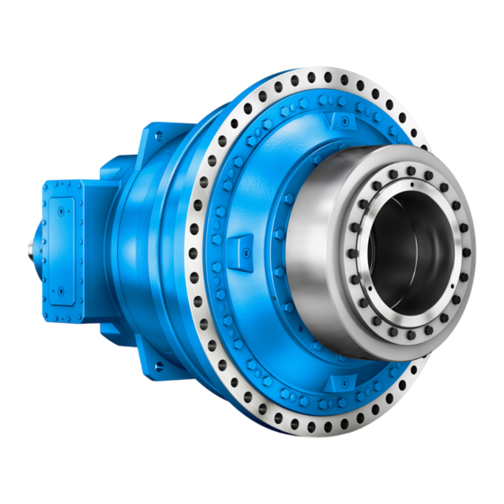
General description
Provides an overview of the planetary gear unit and its applications.
Housing
Describes the housing material and its features like attachment points.
Oil supply to the gear unit
Explains different oil supply versions: splash, pressure, and circulating.
Bearing arrangement of the shafts
States that all shafts are mounted in rolling-contact bearings.
Shaft seals
Details shaft seals, including rotary shaft sealing rings and taconite seals.
Backstop
Describes the mechanical backstop and its principle of operation.
Torque limiting backstop (special version)
Explains the torque-limiting backstop for special applications like twin drives.
Cooling
Covers cooling types like fan, air-oil, and water-oil coolers.
Couplings
Details elastic couplings, their alignment, and balancing requirements.
Shrink disk
Explains the shrink disk as a frictional clamping connection.
Heating
Describes heating elements for preheating gear unit oil at low temperatures.
Oil level indicator
Lists components for checking the oil level visually.
Oil temperature monitoring system
Details the use of Pt 100 resistance thermometers for oil temperature measurement.
Bearing monitoring
Covers bearing monitoring methods: Pt 100, shock-pulse, and acceleration sensor.
Speed encoder
Describes the function and connection of an incremental speed encoder.
Torque monitoring system
Explains telemetry systems and the DX500GL for speed and torque measurement.
Application planning
Scope of delivery
Lists items included in the shipping documents and checks upon receipt.
Transport
Provides instructions for safe transport to avoid damage.
Attachment points
Details how to use sling swivels and the location of attachment points.
Special aspects relating to lubrication
Covers oil filling and oil drain procedures for the gear unit.
Assembly
General assembly instructions
Emphasizes careful mounting by authorized personnel and general precautions.
Unpacking the gear unit
Provides instructions and safety notes for unpacking the gear unit.
Gear unit assembly
Covers foundation requirements and various mounting procedures.
Gear unit dismantling
Details procedures for dismantling gear units with and without shrink disks.
Couplings
Explains coupling installation, alignment, and potential misalignments.
Connecting components
Guides on connecting various components like coolers, sensors, and hoses.
Tightening procedure
Details bolt properties, connection classes, and tightening torques.
Final work
Covers final checks and measures after assembly and connection.
Commissioning
Measures prior to commissioning
Lists essential steps before commissioning the gear unit.
Measures during commissioning
Outlines checks and documentation required during commissioning.
Operation
Operating data
Specifies operating data for the gear unit and its oil.
Anomalies
Lists common anomalous behaviors during operation and initial responses.
Taking the unit out of service
Provides instructions for taking the gear unit out of service for prolonged periods.
Servicing
General maintenance information
Highlights the importance of adhering to stipulated maintenance intervals.
Maintenance schedule
Provides an overview of maintenance and servicing activities at regular intervals.
Service and maintenance work
Details specific tasks like cleaning filters, checking oil, and replacing parts.
Possible faults
Offers a troubleshooting guide for common faults and their remedies.
Service & Support
Contact
Provides contact information for ordering parts or technical queries.
Declaration of incorporation
UK Declaration of Incorporation
Formal declaration regarding the partly completed machine's compliance.
Technical data
General technical data
Explains rating plate information and technical data sources.
Ambient temperature
Specifies the permissible ambient temperature range for gear unit operation.
Types
Lists the available standard gear unit types.
Weights
Provides approximate weights for standard gear units.
Enveloping surface sound pressure level
Lists enveloping surface sound pressure levels according to ISO 9614 Part 2.
Need help?
Do you have a question about the P3DH and is the answer not in the manual?
Questions and answers