
Related Manuals for Advantech UNO-2484G-B731AE


Summarization of Contents
Copyright and Acknowledgments
Copyright Notice
Copyright notice for the manual and software.
Trademarks
Lists trademarks and registered properties.
Support
Product Support
Information on obtaining product support and technical assistance.
Product Warranty
Warranty Terms
Details the warranty terms, exclusions, and claims process.
Declarations and Safety Precautions
Declaration of Conformity
Statements regarding CE and FCC compliance for the product.
Static Electricity Precautions
Instructions to prevent damage from static electricity.
Safety Instructions
General Safety Guidelines
Comprehensive safety guidelines for operating and handling the equipment.
Chapter 1 Overview
Introduction
Introduces the UNO-2484G V2 platform and its capabilities.
Safety Precautions
Lists essential safety measures to prevent injuries during setup.
Packing List
Details the items included in the product package.
Hardware Specifications
Outlines the detailed hardware specifications of the device.
Dimensions
Provides the physical dimensions of the UNO-2484G V2.
Chapter 2 Hardware Functionality
Introduction
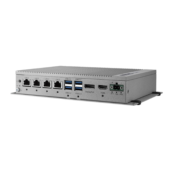
Introduces the chapter and shows connector locations.
Serial Communication Ports
Details the four standard COM serial communication ports.
Power Connector
Explains the Phoenix connector for external power input.
LAN Ethernet Connector
Describes the Gigabit LAN controllers and RJ-45 connectors.
Chapter 2 Module and Port Connections
USB Connector
Details the USB 3.2 and USB 2.0 ports and functionality.
HDMI Connector
Describes the HDMI 1.4 interface for high-resolution output.
DP Connector
Describes the DP 1.4a interface for high-resolution output.
RTC Battery
Explains the function of the RTC battery for system clock retention.
Power Button Power Management
Describes the power button and system power management features.
Reset Button
Explains the function of the hardware reset button.
mPCIe Connector
Details the mPCIe sockets for expansion modules.
M.2 B-key Connector
Describes the M.2 B-key connector for M.2 cards and SIM slot.
Chapter 2 Internal Connectors and Indicators
M.2 M-key Connector
Describes the M.2 M-key connector for NVMe SSDs.
Nano SIM Slot
Mentions the Nano SIM slot for LTE functionality.
LED Indicators
Explains the status indicated by the system's LEDs.
Base Unit Internal Connectors
Shows diagrams of internal connector locations.
Chapter 3 Initial Setup
Chassis Grounding
Details how to properly ground the device for EMI protection.
Connect Power Supply
Instructions on connecting the external power supply to the device.
Open Close Rear Cover
Guide on how to access internal components by removing the rear cover.
Hard Disk Installation
Steps for installing a hard disk drive into the system.
Extension Kit Installation
Instructions for installing optional expansion kits.
Chapter 3 Grounding and Power
Chassis Grounding
Details how to properly ground the device for EMI protection.
Chapter 3 Power Connection
Connect Power Supply
Instructions on connecting the external power supply to the device.
Chapter 3 Rear Cover Operations
Open Close Rear Cover
Guide on how to access internal components by removing the rear cover.
Installing NVME Module
Steps for installing an NVME module into the system.
Chapter 3 Module Installation
Installing miniPCIe Module
Steps for installing a miniPCIe module into the system.
Chapter 3 M.2 Module Installation
Installing M.2 B Key Module
Steps for installing an M.2 B Key module into the system.
Chapter 3 M.2 2242 Module Installation
Installing M.2 B key 2242 Module
Steps for installing an M.2 B key 2242 module into the system.
Chapter 3 SSD Module Installation
Installing 2.5” SSD Module
Steps for installing a 2.5-inch SSD module into the system.
Chapter 3 Expansion Kit Installation
Installing Expansion Kit
Instructions for installing optional expansion kits.
Chapter 4 BIOS Operations
Introduction
Covers basic navigation and configuration within the system's BIOS.
Chapter 4 BIOS Setup Navigation
Introduction
Introduces the BIOS setup utility and its functions.
Entering BIOS Setup
Explains how to access and navigate the BIOS setup utility.
Main Menu
Describes the main menu screen of the BIOS setup.
Chapter 4 Advanced BIOS Features
Advanced BIOS Features
Details various advanced BIOS settings and configurations.
Chapter 4 CPU Configuration
CPU Configuration
Explains the CPU-related settings available in the BIOS.
Chapter 4 Power and Performance Settings
Power & Performance
Covers settings related to power management and system performance.
Chapter 4 Chipset and PCH Configuration
PCH-FW Configuration
Details settings related to the PCH-FW (Platform Controller Hub Firmware).
ACPI Settings
Describes ACPI (Advanced Configuration and Power Interface) settings.
Super IO Configuration
Details configuration options for the NCT61260 Super IO chip.
Chapter 4 Hardware Monitoring and USB Configuration
H/W Monitor Configuration
Covers hardware monitoring settings for system status.
USB Configuration
Details USB configuration parameters and settings.
Chapter 4 RTC and CSM Configuration
S5 RTC Make Settings
Describes settings for waking the system from S5 state using the RTC alarm.
Chapter 4 Boot and Security Settings
CSM Configuration
Covers CSM (Compatibility Support Module) configuration options.
NVMe Configuration
Details NVMe device option settings.
Boot
Details boot configuration options and boot priorities.
Chapter 4 Save and Exit BIOS
Save & Exit
Explains how to save changes and exit the BIOS setup.
Appendix A Pin Assignments and Settings
Power Connector Pin Assignments
Details the pin assignments for the DC power input connector.
Clear CMOS Function
Explains the jumper for clearing CMOS settings.
USB Connector Pin Assignments
Details the pin assignments for the USB connectors.
Appendix A Display and M.2 Connector Details
HDMI Connector Pin Assignments
Details the pin assignments for the HDMI connector.
M.2 B-Key Connector Pin Assignments
Details the pin assignments for the M.2 B-Key connector.
M.2 M-Key Connector Pin Assignments
Details the pin assignments for the M.2 M-Key connector.
Appendix A PCIe and COM Port Details
mPCIe Connector Pin Assignments
Details the pin assignments for the mPCIe connectors.
COM Port RS232/422/485 Settings
Details the pin assignments for COM ports in RS232, RS422, and RS485 modes.
Appendix A Network and GPIO Details
LAN RJ45 Connector
Details the pin assignments and LED indicators for the RJ45 LAN connectors.
GPIO Port Pin Assignments
Details the pin assignments for the GPIO port.
Appendix A DisplayPort and Type-C Connector Details
DP Connector Pin Assignments
Details the pin assignments for the DisplayPort connector.
Type-C Connector Pin Assignments
Details the pin assignments for the USB Type-C connector.
Appendix A Special Settings
AT/ATX Setting
Explains the jumper settings for AT/ATX power modes.
DC in Setting
Describes the DC input setting for iDoor modules.
Appendix A Module Settings
Slide Switch Setting
Details the slide switch settings for 5G modules.
Remote Power Setting
Describes the remote power setting for iDoor modules.
RAID0 RAID1 Setting
Steps to enable RAID0/RAID1 support via VMD configuration.
Need help?
Do you have a question about the UNO-2484G-B731AE and is the answer not in the manual?
Questions and answers