Table of Contents
Advertisement
®
®
™
Bendix
Gen 4
and Gen 5
™
™
GEN 4
AND GEN 5
This manual describes both the cab mount and the frame
mount versions of the Bendix
Brake System/Automatic Traction Control (ABS/ATC)
systems.
Both cab and frame mount versions are designed for:
•
Tractors
•
Trucks
•
Buses and
•
Motor Coaches and
•
RVs.
This manual covers:
•
ABS/ATC Operation
•
System Components
•
Service Procedures
•
Diagnosis and
•
Troubleshooting Procedures.
For information on disassembly, installation, and service of
related axle and brake components, refer to their individual
Bendix Service Manuals.
For assistance in your area call Bendix at 1-800-247-2725
or RoadRanger
®
at 1-800-826-4357.
These ABS controllers and systems were originally
marketed by Eaton Corporation under the Eaton
name. For more information contact Bendix, your local
authorized Bendix dealer, or RoadRanger
Document Revision Level
This document is subject to revision.
For updates, please visit www.bendix.com.
™
ABS for Trucks, Tractors, and Buses
Cab-Mounted Models
ABS INTRODUCTION
®
Gen 4
™
and Gen 5
™
Antilock
®
brand
®
.
FIGURE 1 - Bendix
Table of Contents
ABS Operation . . . . . . . . . . . . . . . . . . . . . . . . . . . . . . . 2
ABS Component Function . . . . . . . . . . . . . . . . . . . . . . 3
ABS Indicator Lamp . . . . . . . . . . . . . . . . . . . . . . . . . . . 3
ABS Trailer Indicator Lamp . . . . . . . . . . . . . . . . . . . . . 3
Automatic Traction Control (ATC) System . . . . . . . . . . 4
Component Overview . . . . . . . . . . . . . . . . . . . . . . . . . 5
Electronic Control Units (ECUs) . . . . . . . . . . . . . . . . . 7
ABS Valves . . . . . . . . . . . . . . . . . . . . . . . . . . . . . . . . . 9
Modulator Valve Operation Modes . . . . . . . . . . . . . . . 10
Optional Front Axle Modules . . . . . . . . . . . . . . . . . . . 11
Diagnostics . . . . . . . . . . . . . . . . . . . . . . . . . . . . . . . . 13
Troubleshooting Procedures . . . . . . . . . . . . . . . . . . . 13
System Configurations . . . . . . . . . . . . . . . . . . . . . . . 15
ServiceRanger PC Software . . . . . . . . . . . . . . . . . . . 16
Test Equipment . . . . . . . . . . . . . . . . . . . . . . . . . . . . . 16
Reading Configuration Codes . . . . . . . . . . . . . . . . . . 18
Retrieving Diagnostic Trouble Codes . . . . . . . . . . . . . 18
Configuration . . . . . . . . . . . . . . . . . . . . . . . . . . . . . 20
Disabling ATC for Dyno Testing . . . . . . . . . . . . . . . . . 20
Speed Sensor Troubleshooting . . . . . . . . . . . . . . . . . 25
Wheel End Speed Sensor Repair . . . . . . . . . . . . . . . 28
ABS Modulator Valve . . . . . . . . . . . . . . . . . . . . . . . . . 33
Troubleshooting . . . . . . . . . . . . . . . . . . . . . . . . . . . 34
Performance Test of the Relay Valve . . . . . . . . . . . . . 34
ATC Valve Removal . . . . . . . . . . . . . . . . . . . . . . . . . . 36
Cab Mount ECU Pin Identification . . . . . . . . . . . . . . . 39
Frame Mount ECU Pin Identification . . . . . . . . . . . . . 43
®
®
Eaton
, RoadRanger
, and ServiceRanger
trademarks of Eaton Corporation.
Frame-Mounted Model
®
ABS Controller Assemblies
®
are registered
26
1
Advertisement
Table of Contents
Troubleshooting

Related Manuals for BENDIX GEN 4 GEN 5 ABS


Summary of Contents for BENDIX GEN 4 GEN 5 ABS
-
Page 1: Table Of Contents
ABS Modulator Valve ......33 For assistance in your area call Bendix at 1-800-247-2725 Automatic Traction Control (ATC) Valve or RoadRanger ®... -
Page 2: Abs Operation
When inactive, the pressure modulator valves provide ANTILOCK BRAKING SYSTEM (ABS) straight-through-passages for supply air to the brake ABS-controlled braking ensures optimum vehicle stability chambers. During ABS operation (an ABS “event”), the while minimizing the stopping distance. During vehicle control unit operates the valves to override the supply of operation, the ABS Electronic Control Unit (ECU) air to the chambers. -
Page 3: Abs Component Function
ABS Component Function ABS Indicator Lamp The ABS system operates as follows (see Figure 2). This lamp is the primary indicator of the ABS status. 1. Speed sensors on each wheel monitor wheel rotation. • The ABS lamp illuminates steadily for a two second 2. -
Page 4: Automatic Traction Control (Atc) System
Automatic Traction Control (ATC) System Thermal (Brake Heat) Protection The ATC system is available on all Standard ABS ECU’s. To prevent excessive brake and drum temperature resulting ATC is not available on Basic ECU’s. It helps improve from brake activity, ATC incorporates a brake temperature traction on slippery or unstable driving surfaces by estimation algorithm to determine when differential braking preventing excessive wheel spin. -
Page 5: Component Overview
Component Overview Bendix ABS components include: • Electronic Control Unit (ECU): The ECU monitors • ATC Valve: The traction control valve applies full system and controls the ABS. It also diagnoses ABS pressure to the relay valve during traction control... - Page 6 FIGURE 5 - ABS Components...
-
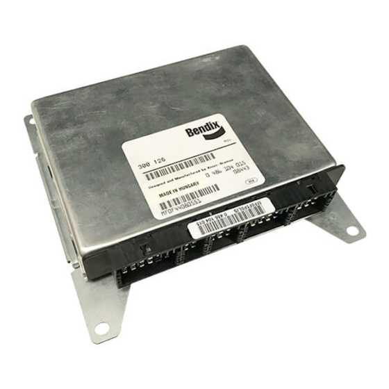
Page 7: Electronic Control Units (Ecus)
ECUs are available in 4 and 6-channel versions with either J1922 or J1939 data links. There is also a 24- volt version. Further service information is available on www.bendix.com. Bendix Part Number Bendix Part Number Serial Number Date Code... - Page 8 Sliding Lock ECU Cover Blank Connector ECU Connector (1 of 4) ™ ™ ™ Gen 4 & Gen 5 ABS – Standard Frame Mount Gen 5 ABS (PLC - Basic Frame Mount) FIGURE 7 - Available Bendix ABS Electronic Control Units...
-
Page 9: Abs Valves
ABS Valves The ABS modulator valve controls air pressure to individual 1/2 NPT brake assemblies. Depending on the particular ABS Delivery Port configuration, a system may utilize three, four or six modulator valves. See Figure 8. Each modulator valve contains two air control solenoids, which act as pilots to the hold and release diaphragms. -
Page 10: Modulator Valve Operation Modes
Vents Solenoid Hold Inlet Diaphragm Zero Inlet Pressure Outlet Outlet Release Diaphragm Exhaust Exhaust FIGURE 11 - Normal Release FIGURE 10 - Normal Apply and ABS/ATC Apply Inlet Inlet Outlet Outlet Exhaust Exhaust FIGURE 12 - ABS/ATC Hold FIGURE 13 - ABS/ATC Release Modulator Valve Operation Modes 3. -
Page 11: Optional Front Axle Modules
Wheel End Sensors • 6-8 PSIG. For most applications, Bendix ABS uses standard wheel end sensors (see figure 15). The front sensor is accessible on the inboard side of the steering knuckle. The rear drive axle sensor is accessible by removing the wheel and drum assembly. - Page 12 Electrical Layout Rear Axle Valve Assembly Speed Sensor Indicator Lamps ABS Tractor Indicator Lamp (IL) ABS Trailer IL (after 3/1/01) ATC Lamp (when ATC equipped) Electronic Control Unit (ECU) Cab Mount or Frame Mount Diagnostic Connector Diagnostic Switch Front Axle Traction Control Valve ABS Off Road Switch (optional) Pressure...
-
Page 13: Diagnostics
DIAGNOSTICS recommended procedures, deactivate the electrical An important feature of Bendix ABS is the system diagnostic system in a manner that safely removes all capability. This section describes how to retrieve electrical power from the vehicle. configuration information and error codes to troubleshoot 6. - Page 14 Cycle ignition key OFF to ON Observe ABS indicator lamp operation Lamp turns OFF after Lamp stays ON Lamp never ON 2 second lamp check Check for power to ABS ECU. ABS system not reporting Select Eaton ABS diagnostic tool Check indicator lamp and wiring Codes–perform traditional foundation brake...
-
Page 15: System Configurations
® implemented. The diagnostic switch, MPSI Pro-Link tool SYSTEM CONFIGURATIONS or ServiceRanger PC software may be used to configure Available Configurations to a higher level (add components or functionality). If it is desired to move the configuration downward (fewer A wide variety of system configurations are available (refer components than standard), the ProLink tool or to Figure 17). -
Page 16: Serviceranger Pc Software
ServiceRanger PC Software Test Equipment ServiceRanger PC software can be used to read and clear Bendix recommends the use of the following products to error codes and obtain a short description of failures. The troubleshoot the ABS system: software can initiate test sequences for controller outputs •... - Page 17 CAUTION: The ProLink hand-held tester can activate ® An MPSI ProLink hand-held tester with Bendix proprietary output tests for all output devices. Since these tests can cartridge can be used to read and clear error codes and affect operation of the vehicle braking system, the ECU obtain a short description of failures.
-
Page 18: Reading Configuration Codes
Diagnostic Switch Retrieving Diagnostic Trouble Codes • Turn the ignition key to “ON.” Blink Codes – System Configuration and System Faults. • If vehicle is equipped with ATC, apply and release brakes By properly actuating the ABS diagnostic button, once before proceeding. configuration codes and diagnostic trouble codes can be retrieved as blinked sequences on the ABS indicator lamp. - Page 19 Blink Code Sequence VOLTAGE CONFIGURATIONS Flashes Description 12 Volt System 24 Volt System ABS CONFIGURATIONS 1.5 Sec. Flashes Description Pause 4 Sensors/4 Modulator Valves 4 Sensors/3 Modulator Valves 6 Sensors/4 Modulator Valves 6 Sensors/6 Modulator Valves 6 Sensors/5 Modulator Valves –...
-
Page 20: Clearing Diagnostic Trouble Codes And/Or System Configuration
Clearing Diagnostic Trouble Codes and/or Disabling ATC for Dyno Testing System Configuration • Turn the ignition key to “ON.” • With the ignition “OFF” press and hold the diagnostic • Press and hold the diagnostic button for at least 3 button. -
Page 21: Blink Codes Description
Blink Codes MID 136 Location Description SID/FMI 1st. 2nd. –/– No Trouble Found 001/000 Sensor air gap too large. Left Steer Sensor 001/008 Air gap too large or sensor shorted. 001/010 Speed Sensor signal is noisy. 001/008 Wheel locked too long during an ABS cycle. 001/008 High deceleration rate at wheel site or sensor shorted. - Page 22 Blink Codes MID 136 Location Description SID/FMI 1st. 2nd. 005/000 Sensor air gap too large. Left Rear Sensor. 005/008 Air gap too large or sensor shorted. 005/010 Speed Sensor signal is noisy. 005/008 Wheel locked for too long during an ABS cycle. 005/008 High deceleration rate at wheel site or sensor shorted.
- Page 23 Blink Codes MID 136 Location Description SID/FMI 1st. 2nd. 009/003 Short circuit from the release solenoid to voltage. Left Rear Axle PMV. 009/004 Short circuit from the release solenoid to ground. 009/005 Open circuit at the release solenoid. 009/005 Open circuit on the common line to the valve. 009/003 Short circuit from the hold solenoid to voltage.
- Page 24 Blink Codes MID 136 Location Description SID/FMI 1st. 2nd. 018/003 Solenoid in ATC valve shorted high. ATC Valve. 018/004 Solenoid in ATC valve shorted to ground. 018/005 ATC valve open circuit. 018/002 ATC valve found when it should not be present. 249/002 or 231/002 Time-out or no connection to engine link (J1922/1939).
-
Page 25: Speed Sensor Troubleshooting
Speed Sensor Troubleshooting Follow the steps listed below to locate and correct sensor related ABS trouble codes. 1. Access active trouble code(s) using either the Blink Code procedure, with ServiceRanger or the Hand-held Tester procedure. 2. Lookup the code description, the possible causes and the repair procedures provided in this section. -
Page 26: The 17•12 Sensor Memory Diagnostic Trouble Code
The 17•12 Sensor Memory Diagnostic Trouble Note: If sensor codes still exist, the ABS indicator lamp Code will remain lit. The trouble codes will be logged once again after driving the vehicle. If more than one sensor site is The ABS indicator lamp indication and 17•12 diagnostic affected, the codes may not be re-logged by the ECU until trouble code are provided to remind the service technician the vehicle has been driven and held above 20 mph for 3-... - Page 27 Blink Code Sequence Flashes Location Left Steer Right Steer Left Rear Right Rear Left Rear Rear Right Rear Rear 1.5 Sec. Flashes Condition Action Pause If necessary, clean and lubricate sensor. Press into mounting hole until it bottoms against Sensor air gap too large. tone wheel.
-
Page 28: Wheel End Speed Sensor Repair
Wheel End Speed Sensor Repair Installation 1. Install the sensor bushing with the flange stops towards Front Axle Speed Sensor the inboard side of the vehicle. The front axle speed sensor is located on the inboard side 2. Apply high-temperature silicon-based grease to the of the steering knuckle. - Page 29 Rear Axle Speed Sensor Installation 1. Install the sensor bushing with the flange stops toward The rear axle speed sensor located inside the brake drum the inboard side of the vehicle. and is only accessible by removing the wheel and drum assembly.
-
Page 30: Pressure Modulator Valve (Pmv) Troubleshooting
Pressure Modulator Valve (PMV) Troubleshooting Relay Follow the steps listed below to locate and correct ABS modulator valve problems. 1. Access active trouble code(s) using either the Blink Code procedure or the hand-held tester procedure. 2. Lookup the code description, the possible causes and the repair procedures provided in this section. - Page 31 Cab Mount Frame Mount TOP – Looking into harness connector X1 Grey X4 Brown X2 Black X3 Green Harness Connector Circuit Description Harness Connector Circuit Description B (6-Way) PMV 1 (Release) Left Steer X2 (Black) PMV 1 (Hold) Left Steer PMV 1 (Hold) Left Steer PMV 1 (Release) Left Steer PMV 1 Common Left Steer...
- Page 32 Blink Code Sequence Flashes Location Flashes Location PMV4 Right Rear PMV 1 Left Steer PMV5 Left Rear Rear PMV 2 Right Steer PMV6 Right Rear Rear PMV 3 Left Rear Flashes Condition Action Use multimeter to check that valve resistances are correct. There is a short between the 1.5 Sec.
-
Page 33: Abs Modulator Valve
ABS Modulator Valve Installation 1. Install the valve. Torque fasteners to manufacturers Removal specification. 1. Turn ignition switch to the OFF position, and apply 2. Connect air lines. parking brake. • Supply to port 1 on valve. CAUTION: Block wheels before beginning this procedure. •... -
Page 34: Automatic Traction Control (Atc) Valve Troubleshooting
Performance Test of the Relay Valve Automatic Traction Control (ATC) Valve Troubleshooting CAUTION: Block wheels before beginning this procedure. Follow all standard safety procedures, outlined by, but not The following ATC troubleshooting pages provide the basic limited to, the General Precautions listed on page 13 of information necessary to: identify the diagnostic trouble this document. - Page 35 Cab Mount Frame Mount TOP – Looking into harness connector X1 Grey X2 Black X3 Green X4 Brown Harness Connector Circuit Description Harness Connector Circuit Description A (18-Way) ATC Mud and Snow Switch X1 (Grey) ATCL (ATC Light/ATC Switch) ATCL (ATC Light) X3 (Green) ATC Valve –...
-
Page 36: Atc Valve Removal
3. Install the wiring connector to the ATC valve. ATC Valve Removal 4. Test the installation. CAUTION: Block wheels before beginning this procedure. Follow all standard safety procedures, outlined by, but not • Traction Control Valve – Leak Test: limited to, the General Precautions listed on page 13 of Make and hold brake application. - Page 37 Blink Code Sequence Flashes Location Power Circuits Flashes Condition Action Excessive voltage on PMV Power Verify that vehicle system voltage is OK (i.e. 9 to 16 volts). If voltage is out of 1 or 5 1.5 Sec. range, correct system problem. Unplug connector at ECU and turn on ignition Pause switch.
- Page 38 Blink Code Sequence Flashes Location Miscellaneous Action Flashes Condition Retarder control relay shorted high or Use multimeter to verify proper voltage at the retarder control relay. open circuit. 1.5 Sec. Retarder control relay shorted low. Use multimeter to verify proper voltage at the retarder control relay. Pause or open circuit J1922/1939 data link not functioning.
-
Page 39: Cab Mount Ecu Pin Identification
Cab Mount ECU Pin Identification This section shows how to identify Cab Mount ECU harness connectors and pin locations. The charts provide a brief description of the signal carried by each pin. Looking Into Harness Connector Connector A 18 -Way Connector B 6 -Way Connector C... - Page 40 CONNECTOR DESCRIPTION CONNECTOR DESCRIPTION D (15-Way) PMV3 (Left Rear), Rel Solenoid A (18-Way) J1922/J1939 - Gen 4 ™ ABS J1939 Shld/Gen 5 ™ ABS TIL PMV3 (Left Rear), Hold Solenoid PMV3 (Left Rear), Common J1922/J1939 + ATC Valve - Off Road ABS Switch (ORS) Speed Sensor 4 (Left Rear) + ATC Mud &...
- Page 41 FIGURE 42 - Gen 4 ™ and Gen 5 ™ Basic Cab Mount ABS Electrical Schematic...
- Page 42 ™ ™ FIGURE 43 - Gen 4 and Gen 5 Standard Cab Mount ABS Electrical Schematic...
-
Page 43: Frame Mount Ecu Pin Identification
Frame Mount ECU Pin Identification This section shows how to identify Frame Mount ECU harness connectors and pin locations. The charts provide a brief description of the signal carried by each pin. X2 Black X3 Green X3 Green X4 Brown X1 Grey FIGURE 44 - Cab Mount ECU –... - Page 44 X1 Grey X3 Green Signal Description Signal Description X1-1 Ignition-1 X3-1 Speed Sensor, Left Rear- X1-2 Ignition-2 X3-2 Speed Sensor, Left Rear+ X1-3 ATCL ATC Light/ATC Switch X3-3 Speed Sensor, Right Rear- X1-4 1587 J1587+ X3-4 Speed Sensor, Right Rear+ X1-5 Retarder Control X3-5...
- Page 45 ™ FIGURE 46 - Gen 5 Basic Frame Mount ABS Electrical Schematic...
- Page 46 FIGURE 47 - Gen 4 ™ and Gen 5 ™ Standard Frame Mount ABS Electrical Schematic...
- Page 47 Glossary ABS — Antilock Brake System. IR — Independent Regulation. A control method in which a wheel is controlled at optimum slip, a point where retardation and ABS Event — Impending wheel lock situation that causes the stability are maximized. The brake pressure that is best for the ABS controller to activate the modulator valve(s).
- Page 48 BW2261 © 2006 Bendix Commercial Vehicle Systems LLC. All rights reserved. 5/2006 Printed in U.S.A.
Need help?
Do you have a question about the GEN 4 GEN 5 ABS and is the answer not in the manual?
Questions and answers