Table of Contents
Advertisement
®
®
™
Bendix
A-18
Trailer ABS (Gen 4
™
GEN 4
AND GEN 5
This manual describes the Bendix
system and contains two primary sections:
•
Installation
•
Service
The Installation section provides the information required
for the proper installation of a FMVSS-121 compliant trailer
air brake systems that incorporate the Bendix Trailer ABS
system and complementary trailer components.
The Service section of the manual includes the information
necessary to properly maintain, troubleshoot and repair the
A-18
™
trailer ABS system.
Following the installation, service, and troubleshooting
procedures contained in this manual will produce a high
performance, long life, low maintenance antilock braking
system.
For assistance in your area call Bendix at 1-800-247-2725
or RoadRanger
®
at 1-800-826-4357.
Benefits of Trailer ABS
ABS-controlled trailer braking ensures optimum vehicle
stability while minimizing the stopping distance. During
vehicle operation, the trailer ABS Electronic Control Unit
(ECU) continuously monitors all wheel speed sensors. Data
input from the wheel speed sensors allows the ECU to:
•
Detect impending wheel lock.
•
Maintain optimum wheel slip.
•
Maximize overall braking effectiveness.
•
Minimize tendencies for trailer swing out during hard
braking conditions.
Document Revision Level
This document is subject to revision.
For updates please visit www.bendix.com.
™
™
ABS INTRODUCTION
®
™
A-18
trailer ABS
™
and Gen 5
ABS)
Power Requirements for ABS . . . . . . . . . . . . . . . . . . . 3
General Air Brake Requirements . . . . . . . . . . . . . . . . . 4
Brake Priority Options . . . . . . . . . . . . . . . . . . . . . . . . . 5
ABS Performance Characteristics . . . . . . . . . . . . . . . . 6
ABS Controlled Braking . . . . . . . . . . . . . . . . . . . . . . . . 6
ABS Component Function . . . . . . . . . . . . . . . . . . . . . . 6
Trailer ABS Configurations . . . . . . . . . . . . . . . . . . . . . 7
Sensor Placement . . . . . . . . . . . . . . . . . . . . . . . . . . . . 7
Trailer ABS Component Overview . . . . . . . . . . . . . . . . 9
Electronic Control Unit (ECU) . . . . . . . . . . . . . . . . . . 11
Relay Valve . . . . . . . . . . . . . . . . . . . . . . . . . . . . . . . . 13
Relay Valve Operation Modes . . . . . . . . . . . . . . . . . . 14
Installation . . . . . . . . . . . . . . . . . . . . . . . . . . . . . . . . . 15
Stand Alone Relay Valve . . . . . . . . . . . . . . . . . . . . . 16
Install the Inline Power Connector . . . . . . . . . . . . . . . 17
Install the Main ABS Harness . . . . . . . . . . . . . . . . . . 17
Install the Trailer Mounted Warning Light . . . . . . . . . 18
End-Of-Line Diagnostics . . . . . . . . . . . . . . . . . . . . . . 23
Use of Hand Held Tool for Configuration . . . . . . . . . . 23
Troubleshooting and Fault Codes . . . . . . . . . . . . . . . 25
Test Equipment . . . . . . . . . . . . . . . . . . . . . . . . . . . . . 26
ServiceRanger PC Software . . . . . . . . . . . . . . . . . . . 27
ABS Valve Troubleshooting . . . . . . . . . . . . . . . . . . . . 28
Speed Sensor Troubleshooting . . . . . . . . . . . . . . . . . 29
Accessing Codes . . . . . . . . . . . . . . . . . . . . . . . . . . . . 30
Fault Code Charts . . . . . . . . . . . . . . . . . . . . . . . . . . . 31
Glossary . . . . . . . . . . . . . . . . . . . . . . . . . . . . . . . . . . 39
®
Bendix
is a registered trademark of Bendix Commercial
Vehicle Systems LLC.
Eaton
®
, RoadRanger
trademarks of Eaton Corporation.
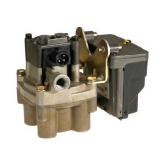
FIGURE 1 - ABS Controller Assemblies
Table of Contents
®
, and ServiceRanger
®
are registered
1
Advertisement
Table of Contents
Troubleshooting

Subscribe to Our Youtube Channel
Related Manuals for BENDIX A-18 TRAILER ABS


Summary of Contents for BENDIX A-18 TRAILER ABS
-
Page 1: Table Of Contents
ABS Component Function ..... . 6 air brake systems that incorporate the Bendix Trailer ABS Trailer ABS Configurations ..... 7 system and complementary trailer components. -
Page 2: Power Requirements For Abs
150 mm (5.9 inches) and not ® Bendix Service Manuals. more than 600 mm (23.6 inches) from the rear red side For assistance in your area call Bendix at 1-800-247-2725 marker indicator lamp. (Refer to Figure 22.) On a converter or RoadRanger ® at 1-800-826-4357. -
Page 3: General Air Brake Requirements
For example: a type 30 air chamber has an effective surface General Air Brake Requirements area of 30 sq. in. For short stroke type 30 air chambers, Basic design requirements for trailer air brake systems are the volume is typically 89 CID. For a typical two axle trailer, set forth in FMVSS-121. -
Page 4: Brake Priority Options
Conventional trailers are designed for either: procedures. A number of spring brake control valves are • Spring Brake Priority or suitable for meeting current requirements. Bendix offers • Service Brake Priority. spring brake valves suitable for a range of applications. -
Page 5: Abs Performance Characteristics
ABS Component Function FIGURE 4 - Overview of Trailer ABS Operation ® Figure 4 shows an overview of the operation of the Bendix ™ A-18 trailer ABS system. Speed sensors (1) monitor wheel rotation and provide information (2) on wheel rotation to the central electronic control unit. -
Page 6: Trailer Abs Configurations
Select low systems are very stable but sacrifice stopping distance on split coefficient Bendix’s standard systems offer either two or four speed surfaces. Modified select low systems incorporate a delay sensors and up to two modulator valves. Standard systems... - Page 7 System Application Chart 4S/2M Axle Control 4S/2M Side Control Trailer Type 2S/1M 2S/2M Semi Trailer Trailer (2) and Trailer Trailer Dolly FIGURE 5 - System Application Chart...
-
Page 8: Trailer Abs Component Overview
• Wheel End Speed Sensor and Tone Wheel: Single Trailer ABS Component Overview point variable reluctance (magnetic) sensor that Bendix ® A-18 ™ trailer ABS system includes the following generates an alternating current signal in response to components: the movement of teeth on a tone wheel. The signal is •... - Page 9 FIGURE 6 - ABS Trailer Components...
-
Page 10: Electronic Control Unit (Ecu)
Electronic Control Unit (ECU) Bendix Part Number ® ™ The Bendix A-18 ECU is the trailer ABS control center. Identification Identification information for the ECU is located on the connector pinout label (refer to Figure 7). The label is located under the ECU cover. Refer to the label for the: •... - Page 11 Inputs Outputs X1-10 Valve A Sensor A X2-4 Common X1-3 X2-3 Hold X1-4 Sensor B X2-6 Release X2-5 X1-12 Valve B Standard Common X1-2 Sensor C X2-8 Trailer Hold X1-1 X2-7 Trailer Mounted (2 Connectors) Warning Light Sensor D X1-9 X2-10 X2-9 X2-2...
-
Page 12: Relay Valve
PERSONAL INJURY OR DEATH: valves are available preassembled to facilitate system When working on or around a vehicle, the following ® installation on a variety of vehicles. Refer to the Bendix general precautions should be observed at all times. A-18 ™... -
Page 13: Relay Valve Operation Modes
2. Normal Release–Pressure at the top of the piston is system pressure has been depleted. vented through the treadle valve. The sleeve rises to 8. Use only genuine Bendix ® replacement parts, block the inlet while allowing the chamber air to exhaust components and kits. -
Page 14: Installation
Install the Wheel Speed Sensors and Sensor Friction Sleeves ® ™ Installation of the Bendix A-18 trailer ABS system is similar from one configuration to another. All systems use the same Refer to the appropriate diagram for your system and locate speed sensors and valves. -
Page 15: Install The Ecu/Relay Valve And Stand Alone Relay Valve
Install the ECU/Relay Valve and Stand Alone Leak and Performance Test Relay Valve 1. Park vehicle on level surface and block wheels. In all installations, the ECU/Relay Valve assembly appears 2. Make and hold brake application. No audible air leaks as Relay Valve “A”... -
Page 16: Install The Inline Power Connector
Install the Inline Power Connector Install the Main ABS Harness 1. Remove power from the trailer. The inline power connector is on the end of the main ABS harness and connects the ABS system to the trailer 2. Unlock the ECU cover and remove. electrical system. -
Page 17: Install The Trailer Mounted Warning Light
Install the Diagnostic Port (Standard System) To Frame Diagnostic On standard systems, the diagnostic port is installed on Port the road side of the trailer, on the frame forward of the trailer axle(s). To install the diagnostics port, bolt or weld the diagnostic port bracket to the trailer frame. -
Page 18: Top View
2S-1M Electrical Configuration (Top View) Power Cable Wheel Sensor Speed Sensor Diagnostic Port (Shown with Extension) ECU Side Trailer Side Side Wheel Side Parts List Description Quantity Sensor B ECU/Relay Valve Sensor/Diagnostics Cable Front Valve/Power Cable Sensor A Sensors — 0.4m Cable Sensor Friction Sleeve J560 Connector Warning Lamp Connector... - Page 19 2S-2M Electrical Configuration (Top View) J560 Connector Power Cable Speed Sensor Wheel Sensor Diagnostic Port ECU Side Trailer Side Side Wheel Side Parts List Description Quantity Sensor B ECU/Relay Valve Front Stand Alone Relay Valve Sensor/Diagnostic Cable Sensor A Valve/Power Cable Sensors —...
- Page 20 4S-2M Side Control Electrical Configuration (Top View) J560 Connector Speed Sensor Power Cable Wheel Sensor Diagnostic Port ECU Side Trailer Side Side Wheel Side Sensor B Parts List Description Quantity Sensor D ECU/Relay Valve Front Stand Alone Relay Valve Sensor/Diagnostic Cable Sensor C Valve/Power Cable Sensors —...
- Page 21 4S-2M Axle Control Electrical Configuration (Top View) J560 Connector Power Cable Wheel Sensor Speed Sensor Diagnostic Port ECU Side Side Trailer Side Wheel Side Sensor D Parts List Description Quantity Sensor B ECU/Relay Valve Front Stand Alone Relay Valve Sensor/Diagnostic Cable Sensor A Valve/Power Cable Sensors —...
-
Page 22: End-Of-Line Diagnostics
1. Apply power to ECU (do not use a battery charger as a power source). 2. Remove the weather cap from the trailer diagnostic port. 3. Connect either a hand-held tester with a Bendix Diagnostic Card or a PC Based Diagnostic system with ServiceRanger’s End-of-Line Software Package to the trailer diagnostic port. - Page 23 Harness Connector ABS Component Harness Terminal Wire Seal Lock Plug Shell Deutsch DT (Deutsch) Socket (Deutsch) W12S-P012 (Deutsch) 114017 (Deutsch) DT06 12SA-BK01 (Grey) 0462-201-16141 DT06 12SB-BK01 (Black) DT06 12SC-B016 (Green) Relay Valve Bayonett Socket (Amp) Seal (Amp) 26570 14414-627-626 Wheel End Sensor 2-Pin Kostal w/overmold Length...
-
Page 24: Troubleshooting And Fault Codes
Troubleshooting and Fault Codes fault codes on the hand-held tester’s display. Refer to ® ™ An important feature of the Bendix A-18 trailer ABS the hand-held tester information later in this section to system is the diagnostics that are reported via the Electronic retrieve and display fault codes. -
Page 25: Test Equipment
Schematics, error codes, and a multimeter can be used to An MPSI hand-held tester with Bendix proprietary cartridge check sensor and solenoid resistances and to find wiring can be used to read and clear error codes and obtain a harness defects. -
Page 26: Serviceranger Pc Software
ServiceRanger PC Software CAUTION: ServiceRanger PC software can activate output ServiceRanger PC software can be used to read and clear tests for all output devices. Since these tests can affect error codes and obtain a short description of failures. The operation of the vehicle braking system, the ECU software can initiate test sequences for controller outputs incorporates special safety protection. -
Page 27: Abs Valve Troubleshooting
Troubleshooting Procedures ABS Valve Troubleshooting Follow the steps listed below to locate and correct ABS 2. Lookup the code description, the possible causes and the repair procedures provided in this section. modulator valve problems. 3. Perform the recommended repair procedures. 1. -
Page 28: Speed Sensor Troubleshooting
Speed Sensor Troubleshooting Follow the steps listed below to locate and correct sensor- related ABS diagnostic trouble codes. 1. Access active diagnostic trouble code(s) using the blink code procedure, the hand-held tester or ServiceRanger software. 2. Look up the code description, the possible causes and the repair procedures provided in this section. -
Page 29: Accessing Codes
On Gen-5 ™ ABS systems, both the configuration codes and Accessing Codes the fault codes are reported separately as two-part blink The ABS Warning Lamp outputs a two-part blink code. To codes. There are different procedures for retrieving interpret the blink code, record the number of flashes in configuration and fault codes. -
Page 30: Fault Code Charts
™ Fault Code Charts Retrieving Fault Codes (Gen-4 ABS) 1. Turn ignition key ON. Fault codes can be retrieved as two-digit blink codes. Refer to Figures 37 and 38 for a description of these codes. 2. Use appropriate jumper method. Apply the jumper for 2 seconds and remove. - Page 31 Check sensor resistance (1500-2500 ohms). ™ FIGURE 37 - Gen 4 ABS Diagnostic Trouble Code Chart...
- Page 32 Blink Code Description Location 1st 2nd No trouble found. Sensor air gap too large. Sensor air gap too large or sensor shorted. Sensor A Noisy signal, check tone ring. Excessive wheel lock. Intermittent sensor signal. Sensor shorted or open. Sensor air gap too large. Sensor air gap too large or sensor shorted.
- Page 33 STANDARD SYSTEM Top–Looking into Harness Connector Cover Lock ECU Cover 1587 1587 DIAG Alignment Cable X2-CODING B X1-CODING A Tabs Connector Guides (BLACK) (GREY) Pin# Ref. Description Pin# Ref. Description Diagnostic Port Ground Valve B, Hold Solenoid Diagnostic Port Power (12V) Valve B, Common Speed Sensor A, Negative Valve A, Common...
- Page 34 White (Ground) Top–Looking into Harness Blue (Switched 12V Constant Power From Tractor) DIAG X1-CODING C (GREEN) (Brake Light Power) ECU Side Wheel Side Front Harness Side Warning Light Side Diagnostic Port Release (Shown with Extension) No Connection Trailer Side Power A–Brake Light Cable Hold...
- Page 35 White (Ground) Top–Looking into Harness Blue (Switched 12V Constant Power From Tractor) 1587 1587 DIAG X2-CODING B (BLACK) X1-CODING A (GREY) (Brake Light Power) ECU Side Wheel Side Front Harness Side Warning Light Side A–SAE J1587+ Trailer Release B–SAE J1587– Side Power C–+12 Volts...
- Page 36 White (Ground) Top–Looking into Harness Blue (Switched 12V Constant Power From Tractor) 1587 1587 DIAG X2-CODING B (BLACK) X1-CODING A (GREY) (Brake Light Power) ECU Side Wheel Side Front Top View Harness Side Warning Road Side Light Side Trailer Release Side Power A–Brake Light...
- Page 37 FIGURE 43 - Electrical Schematic...
-
Page 38: Glossary
Glossary MIR — Modified Independent Regulation. A method of controlling ABS — Antilock Brake System. A control system that maintains the opposite sides of a steer axle during ABS operation so that wheel slip at a level that minimizes stopping distance while torque steer and stopping distance are minimized. - Page 40 BW2262 © 2004 Bendix Commercial Vehicle Systems LLC. All rights reserved. 5/2004. Printed in U.S.A.
Need help?
Do you have a question about the A-18 TRAILER ABS and is the answer not in the manual?
Questions and answers