Advertisement
Quick Links
Bendix Manual Slack Adjusters
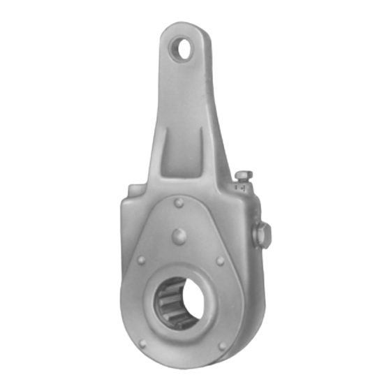
FIGURE 1 - POSITIVE LOCK TYPE SLACK ADJUSTER
DESCRIPTION
In an s-cam type foundation brake, the final link between
the pneumatic system and the foundation brake is the slack
adjuster. The arm of the slack adjuster is fastened to the
push rod of the chamber with a yoke, and the slack adjuster
spline is installed on the brake cam shaft.
Primarily, the slack adjuster is a lever, converting the linear
force of the air chamber push rod into a torque which turns
the brake cam shaft and applies the brakes.
Standard slack adjusters contain four basic components;
the body, worm, gear and adjusting screw. The adjusting
screw is provided to adjust the slack caused by the wear of
the brake lining.
All slack adjusters utilize the worm and gear principle and,
fundamentally, differ only in torque limit specifications; A
type 20 slack adjuster has a limit of 20,000 inch pounds
torque, a type 30 slack adjuster has a limit of 30,000 inch
pounds torque, etc.
Slack adjusters are manufactured with various arm lengths
and various configurations; straight, offset, etc. to satisfy
various installation requirements. Splines are available in
several different types and sizes.
OPERATION
When the brakes are applied, air pressure forces the air
chamber diaphragm and push rod to move; this rotates the
slack adjuster, which in turn rotates the cam shaft. This
causes the "S" cam to spread the brake shoes which contact
the brake drum.
WORM GEAR
LOCK SLEEVE
ADJUSTING SCREW
(WORM SHAFT)
ADJUSTING GEAR
GREASE HOLE
SPLINE
FIGURE 2 - BALL INDENT TYPE SLACK ADJUSTER
When the brakes are released, air pressure is exhausted
from the air chamber. The chamber return spring and the
brake shoe return springs return the brake cam, cam shaft,
slack adjuster and chamber push rod to the released position.
ADJUSTING MECHANISM
The adjusting mechanism of a slack adjuster consists of an
adjusting screw (worm shaft), worm and slack adjuster worm
gear. Turning the adjusting screw nut on the end of the worm
shaft rotates the worm shaft and worm. The worm meshes
with and rotates the slack adjuster worm gear which is
connected to the brake cam by a splined cam shaft. The
turning of the slack adjuster worm gear rotates the cam
shaft and brake cam, spreading the brake shoes,
compensating for brake lining wear.
There are two types of adjusting mechanisms used on Bendix
slack adjusters currently manufactured. The light to medium
torque rated slack adjusters (Fig. 1) use a positive lock
mechanism consisting of a spring loaded lock sleeve, which
when positioned properly, engages the adjusting screw nut,
preventing the adjusting screw (worm shaft) from rotating.
The heavier torque rated slack adjusters (Fig. 2) utilize the
lock ball or plunger and worm shaft indent principle
adjustment lock. The lock ball or plunger must engage the
indent on the worm shaft after the adjustment is completed.
An audible metallic click can be heard when engagement is
made.
WORM SHAFT (LOCK
SCREW)
WORM GEAR
ADJUSTING
GEAR
ADJUSTING SCREW
(WORM SHAFT)
SPLINE
1
Advertisement

Related Manuals for BENDIX SLACK ADJUSTERS


Summary of Contents for BENDIX SLACK ADJUSTERS
- Page 1 All slack adjusters utilize the worm and gear principle and, compensating for brake lining wear. fundamentally, differ only in torque limit specifications; A...
-
Page 2: Brake Adjustment
Using the Positive Lock Slack Adjuster Mechanism: (Fig. 1) Slack Adj. Arm Length Push Rod Movement (stroke) Wipe the adjusting screw nut and locking sleeve area clean. “A” Dim. (in.) “B” Dim. (in.) 1-1/2 Position wrench or socket over the adjusting screw and 5-1/2 1-1/4 disengage the locking sleeve by depressing the lock sleeve. -
Page 3: Disassembly And Assembly
TENSION COMPRESSION PROVIDED THE MAXIMUM TORQUE RATING IS NOT EXCEEDED, BENDIX SLACKS CAN BE MOUNTED IN EITHER DIRECTION AND STILL MEET THE ENGINEERING TEST SPECIFICATION (50K CYCLES AT MAXIMUM RATED LOAD). COMPRESSION MOUNTING IS RECOMMENDED AND WILL YIELD A LONGER SERVICE LIFE. - Page 4 3. Before removing worm shaft, measure height from top of 4. Remove ball indent lock mechanism screw. adjusting screw to the slack adjuster body. This 5. Remove spring and ball. measurement is important, as it serves as a reference 6. Before removing worm shaft, measure height from top of when the worm shaft is reassembled.
- Page 5 6. Lubricate slack adjuster as outlined in “Preventive component or plug unless you are certain all system Maintenance” section. pressure has been depleted. TEST OF REBUILT SLACK ADJUSTERS 8. Use only genuine Bendix ® replacement parts, components and kits. Replacement hardware, After lubricating rebuilt slack adjuster (see “Preventive...
- Page 6 ON) prior to performing any vehicle maintenance where one or more wheels on a drive axle are lifted off the ground and moving. BW1453 © 2007 Bendix Commercial Vehicle Systems LLC All rights reserved. 3/2007 Printed in U.S.A.
Need help?
Do you have a question about the SLACK ADJUSTERS and is the answer not in the manual?
Questions and answers