Table of Contents
Advertisement
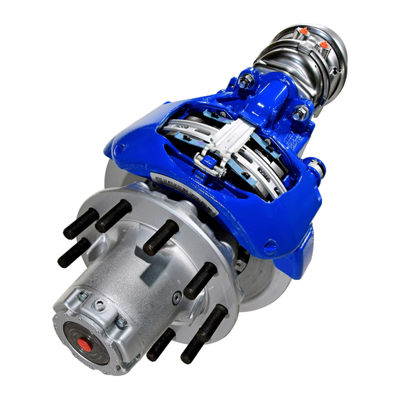
Bendix
ADB 22X
®
DESCRIPTION
Bendix
Air Disc Brakes use a floating caliper design to
®
provide foundation braking on all axles of heavy commercial
vehicles, buses and trailers. Bendix Air Disc Brakes
provide safety and performance, as well as ease of service.
Available in models with or without a combination spring
brake unit, these brakes may also include optional wear
sensors and/or wear diagnostic equipment.
OPERATION
Bendix Air Disc Brakes convert air pressure into braking
force. (See Figure 2.) When the vehicle brakes are
applied, air enters the service brake chamber through
the supply port, applying pressure within the diaphragm.
The pressure expands the diaphragm, applying force to,
and moving the pressure plate and pushrod forward. The
pushrod acts against a cup in the internal lever which
pivots on an eccentric bearing moving the bridge. Moving
against a return spring, the bridge transfers the motion to
two threaded tubes and tappets, which move the inner
brake pad. The inner brake pad (from its normal position of
having a running clearance between it and the rotor) moves
into contact with the brake rotor. Further movement of the
bridge forces the caliper, sliding on two stationary guide
pins, away from the rotor, which pulls the outer brake pad
into the rotor. The clamping action of the brake pads on
the rotor applies braking force to the wheel.
Brake Release and Adjustment
When the vehicle brakes are released, the air pressure
in the service brake chamber is exhausted and the return
springs in the chamber and the bridge return the air disc
brake to a neutral, non-braked position. To maintain the
running clearance gap between the rotor and the brake
pads over time, the non-braked position is mechanically
adjusted by a mechanism in the caliper. The adjustment
mechanism operates automatically whenever the brakes
are activated, to compensate for rotor and brake pad wear
and to keep the running clearance constant. During pad
or rotor maintenance, the technician manually sets the
system's initial non-braked position. The total running
clearance (sum of clearances on both sides of the rotor)
should be between 0.024 to 0.043 in. (0.6 and 1.1 mm).
, ADB 225
, SN6
™
™
, SN7
, SK7
Air Disc Brakes
™
™
™
FIGURE 1 - BENDIX
Service Brake
Return Spring
Outer Brake
Pad
Rotor
FIGURE 2 - CROSS-SECTION VIEW SHOWING BRAKE
OPERATION
ADB 22X
AIR DISC BRAKE
®
™
Pressure
Chamber
Plate
Pushrod
Lever
Eccentric Bearing
Inner Brake Pad
Bridge
Supply Port
Diaphragm
1
Advertisement
Table of Contents

Subscribe to Our Youtube Channel
Related Manuals for BENDIX AIR DISC BRAKE-ADB22X-225-SN6-7-SK7


Summary of Contents for BENDIX AIR DISC BRAKE-ADB22X-225-SN6-7-SK7
-
Page 1: Overview
OPERATION Bendix Air Disc Brakes convert air pressure into braking force. (See Figure 2.) When the vehicle brakes are applied, air enters the service brake chamber through the supply port, applying pressure within the diaphragm. -
Page 2: Safe Maintenance Practices
Not all wheels and valve stems are general precautions should be observed at all times: compatible with Bendix Air Disc Brakes. Use only 1. Park the vehicle on a level surface, apply the parking wheels and valve stems approved by the vehicle brakes, and always block the wheels. -
Page 3: Table Of Contents
SERVICE DATA INDEX Overview ........1 Safe Maintenance Practices....2 Air Disc Brake Sectional and Exploded Views . -
Page 4: Air Disc Brake Sectional And Exploded Views
Inner Boot Assembly Inner Seal Guide Ring Brass Bushing Caliper Top Sectional View Caliper Bolt Cover Adjuster Unit Tappet Bushing Chain Wheel Threaded Tube Shear Adapter Tappet and Boot Assembly 45 Washer Spring Clip Adjuster Cap 27 Spring Pad Retainer Pin Chain Pad Retainer Bridge... -
Page 5: Parts Diagram
Pad Retainer Pin Pad Retainer Spring Clip Washer 18/1 Spring Brake 18/2 Ring Brake Chamber Inner 12/2 Boot Guide Uses White Assembly 4a, 4b 12/1 Pad Assembly Grease Guide Pin One of Three Different Caliper Bolt Styles are Used (Designated by Caliper A, B, or C) Rubber... -
Page 6: Air Disc Brake Identification
AIR DISC BRAKE IDENTIFICATION ROTOR IDENTIFICATION To determine which version of the Bendix air disc brake is Certain maintenance inspection procedures depend on installed, locate the identification label near the guide pin the type of rotor installed (See Page 13). See below for housing. -
Page 7: Preventive Maintenance
PREVENTIVE MAINTENANCE Regular inspection and maintenance of air disc brake Use the table below for a guide to maintenance interval components is an important part of vehicle maintenance. planning, however, depending on the vehicle use, more frequent checks of the components may be necessary. The maintenance practices outlined here are recommended in addition to all standard industry practices (including e.g. -
Page 8: Mechanical Wear Indicators
- Inspect position of wear indicator in use for Bendix air disc brakes. Note: These inspections provide an indication of Style C and D - when to schedule a full wheel-removed inspection of Where the indicator the brake pads and rotor. - Page 9 MECHANICAL BRAKE PAD AND ROTOR WEAR INDICATORS (continued) Style C: Where Both the Carrier and Caliper Have an Indicator Notch Location of Compare the relative position of two notches cast into the Inspection Grooves Carrier and Caliper. See Figure 13. When the two notches align, it is time to schedule a full wheel-removed inspection of the pads and rotor.
-
Page 10: Electronic Wear Indicators, Including Hand Held Diagnostic Equipment
Wear Sensor Pad Retainer Cable To Vehicle Electronic Monitoring System Example of or for use with a Wear Sensor Diagnostic Tool (101) Installed into Slot in Brake Pad Brake Pad Assembly 46 Rotor FIGURE 15 - EXAMPLE OF NORMALLY OPEN OR CLOSED FIGURE 16 - EXAMPLE OF POTENTIOMETER WEAR WEAR SENSOR SENSOR... -
Page 11: Troubleshooting Flowchart
GENERAL TROUBLESHOOTING PROCEDURE FLOWCHART FIGURE 18 - TROUBLESHOOTING BENDIX AIR DISC BRAKES... -
Page 12: Inspections
Follow all standard safety procedures including, but not limited to, those on page 2 of this service manual. BRAKE PADS AND ROTORS Bendix Air Disc Brakes are precision-engineered braking mechanisms. The “friction couple” braking characteristics have been carefully optimized and the rotor design and materials have been matched with special formulation brake pads for optimal performance. -
Page 13: Rotors
Vehicle Manufacturer. It is recommended but is not normally necessary. In the case of severe to install Bendix Brake Rotors, available from your local grooving of the entire friction surface, however, turning Bendix Spicer Foundation Brake parts outlet, and it is... -
Page 14: Caliper Running Clearance
See “Inspect Adjuster Mechanism” on Page 15. CONTACTING BENDIX www.foundationbrakes.com Bendix on-line information is available 24/7. In the on-line contacts directory, you can find: technical support contacts; service engineers; Bendix account managers; international contacts and more. www.foundationbrakes.com is your complete Bendix resource. -
Page 15: Adjuster Mechanism
(See Figure 27) on the shear adapter, make five to ten moderate applications of the brakes [at about 30 psi (2 Bar)]. For a normally functioning Bendix air disc brake, the box-end wrench or socket should turn clockwise in small increments. -
Page 16: Guide Pins
GUIDE PINS CAUTION: Follow all standard safety procedures Tappet and Boot Guide Pin Brass Bushing Assembly including, but not limited to, those on page 2 of this Caliper service manual. See the vehicle manufacturer's recommendations. When working on foundation Cover brakes, be sure that the vehicle is on level ground, LONG BEARING SIDE... - Page 17 CALIPER/ WARNING: Not all wheels and valve stems are CARRIER ASSEMBLY MUST BE REPLACED if this compatible with Bendix Air Disc Brakes. Use only happens. wheels and valve stems approved by the vehicle...
-
Page 18: Maintenance Procedures
45 Washer potential pinch hazard areas. 26 Clip As noted earlier, Bendix Air Disc Brakes are precision- engineered braking mechanisms. The “friction couple” FIGURE 31 - BRAKE PAD REMOVAL braking characteristics have been carefully optimized and the rotor design and materials have been matched with special formulation brake pads for optimal performance. - Page 19 Inboard...
-
Page 20: Electronic Wear Indicator Replacement
ELECTRONIC WEAR INDICATOR REPLACEMENT (Normally-Closed or Normally-Open Type) See page 10. New wear indicators are normally installed whenever brake pads are replaced. Please see Brake Pad Installation on Page 18 for cautions and procedures. The wear indicator is installed after the new brake pads are installed into the Outboard Pad Long brake, but before the retainer hardware. - Page 21 105a short cable end 7. Install the indicator cable (101) in 6. Press the wear indicator cable the middle of the pad retainer (11). (101) into the locating tabs of the Insert the cable guide (105a) at one cable guide (105) (see arrows A). The side of the pad retainer (11) (see short cable end of the wear indicator arrow B).
-
Page 22: Tappet And Boot Assemblies Replacement
TAPPET AND BOOT ASSEMBLIES REPLACEMENT CAUTION: Follow all standard safety procedures including, but not limited to, those on page 2 of this service manual. See the vehicle manufacturer's recommendations. When working on foundation brakes, be sure that the vehicle is on level ground, that the vehicle is parked by other means than the foundation brakes, and that the wheels are chocked. - Page 23 2.76 in. (70 mm) FIGURE 42 - USE OF A SPACER (OFF VEHICLE USE) FIGURE 40 - WEDGE TOOL USE FIGURE 43 - ON VEHICLE BOOT INSTALLATION FIGURE 41 - USE OF A NEW BRAKE PAD AS A SPACER INSPECT THE THREADED TUBES (16) For the inspection of the threads, the tubes must be extended, but by less than 1.18 in.
- Page 24 - see Figure 45. After assembly, check that the tappet (13) is free to turn FIGURE 47 - OFF VEHICLE TAPPET INSTALLATION in both directions. Note: When installing the tappet for Bendix ADB 22X ® ™...
-
Page 25: Carrier/Caliper Assembly Replacement
Note: Replacement bolts diaphragm in the area of the actuator attachment. Remove are not supplied by Bendix - use only those of a grade and the cap or tape only after installing the replacement type specified by the vehicle manufacturer. Consult the caliper on the vehicle. -
Page 26: Brake Actuator And Spring Brake Replacement
CAUTION: Replace actuator and spring brakes only with the same as originally installed on the vehicle. Replacement with alternate equipment (without written authorization from Bendix and the vehicle manufacturer) could compromise brake performance. CAUTION: Follow all standard safety procedures including, but not limited to, those on page 2 of this 18/2 service manual. - Page 27 Spring Brake Removal CAUTION: Follow all standard safety procedures - see note above. Be familiar with the spring brake manufacturer’s recommended safety practices. With all air pressure drained from the air brake system, disconnect the air hose from the brake chamber (18/1). 18/1 Back out the release bolt (Figure 53, arrow D) using a maximum torque of 26 ft.
- Page 28 BW7308 ©2005 Bendix Spicer Foundation Brake LLC • All rights reserved. • 12/05 • Printed in U.S.A.
Need help?
Do you have a question about the AIR DISC BRAKE-ADB22X-225-SN6-7-SK7 and is the answer not in the manual?
Questions and answers