Advertisement
Quick Links
Chipsmall Limited consists of a professional team with an average of over 10 year of expertise in the distribution
of electronic components. Based in Hongkong, we have already established firm and mutual-benefit business
relationships with customers from,Europe,America and south Asia,supplying obsolete and hard-to-find components
to meet their specific needs.
With the principle of "Quality Parts,Customers Priority,Honest Operation,and Considerate Service",our business
mainly focus on the distribution of electronic components. Line cards we deal with include
Microchip,ALPS,ROHM,Xilinx,Pulse,ON,Everlight and Freescale. Main products comprise
IC,Modules,Potentiometer,IC Socket,Relay,Connector.Our parts cover such applications as commercial,industrial,
and automotives areas.
We are looking forward to setting up business relationship with you and hope to provide you with the best service
and solution. Let us make a better world for our industry!
Contact us
Tel: +86-755-8981 8866 Fax: +86-755-8427 6832
Email & Skype: info@chipsmall.com Web: www.chipsmall.com
Address: A1208, Overseas Decoration Building, #122 Zhenhua RD., Futian, Shenzhen, China
Advertisement

Related Manuals for red lion PAXI0020


Summarization of Contents
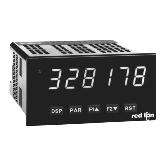
MODEL PAX - 1/8 DIN DIGITAL INPUT PANEL METERS
General Product Description
Provides a comprehensive overview of the meter's features, capabilities, and intended applications in industrial environments.
Safety Precautions and Warnings
Details critical safety instructions, warnings, and precautions to ensure safe installation and operation of the meter.
Physical Dimensions and Panel Cutout
Specifies the physical dimensions of the meter and the required panel cutout for installation.
Product Ordering and Options
Available Meter Models and Part Numbers
Lists the various meter models and their corresponding part numbers for ordering.
Optional Plug-in Cards and Accessories
Details the available optional plug-in cards and accessories that can enhance the meter's functionality.
Technical Specifications of the Meter
Electromagnetic Compatibility (EMC) Compliance
Outlines the meter's compliance with electromagnetic compatibility standards for industrial environments.
Operating and Storage Environmental Conditions
Specifies the environmental conditions, including temperature and humidity, for meter operation and storage.
Electrical Connections and Unit Construction
Details the electrical connection methods and the physical construction of the meter unit.
Weight
Indicates the weight of the meter unit.
PAXC 1/8 DIN Counter Model
PAXC Specifications and Maximum Frequencies
Details the specific technical specifications and maximum input frequencies for the PAXC counter model.
PAXC Inputs, Displays, and Annunciators
Explains the input capabilities, display features, and annunciators for the PAXC counter model.
PAXR 1/8 DIN Rate Meter Model
PAXR Specifications and Input Configuration
Details the specific technical specifications and input configuration for the PAXR rate meter model.
PAXR Rate Display and Annunciators
Explains the rate display features and annunciators for the PAXR rate meter model.
PAXI 1/8 DIN Counter/Rate Meter Model
PAXI Specifications and Maximum Frequencies
Details the technical specifications and maximum input frequencies for the PAXI counter/rate meter model.
PAXI Inputs, Displays, and Prescaler Features
Explains the input capabilities, display features, and prescaler functionalities for the PAXI model.
Optional Plug-in Cards for Extended Functionality
PAXI Communication Cards (PAXCDC)
Details the optional communication cards available for the PAXI meter, including serial and bus options.
Setpoint Alarm Cards (PAXCDS)
Describes the optional plug-in cards that provide setpoint alarm outputs for the meter.
Analog Output Cards (PAXCDL)
Details the optional plug-in cards that provide analog output signals from the meter.
Meter Installation Procedure
Panel Mounting and Installation Environment
Guides on proper panel mounting and considerations for the installation environment.
Configuring Jumpers and DIP Switches
Jumper and Input DIP Switch Settings
Explains how to configure the internal jumper and input DIP switches for meter setup.
Procedure for Installing Plug-in Cards
Steps for Installing Plug-in Cards
Provides a step-by-step guide for safely installing plug-in cards into the meter.
Meter Wiring Guidelines
General Wiring Overview and EMC Installation
Covers general wiring practices and essential EMC installation guidelines for industrial applications.
Power Wiring and User Input Connections
Details the procedures for wiring the meter's power supply and user input terminals.
Input Signal Wiring Configurations
Wiring for Different Input Signal Types
Illustrates wiring methods for various input signal types, including magnetic pickups and TTL.
Wiring for Setpoint, Serial, and Analog Outputs
Provides wiring guidance for setpoint alarms, serial communication, and analog output plug-in cards.
Understanding the Front Panel and Display
Front Panel Buttons and Display Mode Operations
Explains the function of each front panel button and how to navigate display modes.
Programming Mode Operations and Navigation
Details how to enter and navigate the meter's programming modes using front panel keys.
Meter Programming Guide
Programming Menu Structure and Overview
Provides an overview of the meter's programming menu structure and module organization.
Navigation and Value Entry Methods
Explains how to navigate through programming modules and enter parameter values.
Programming Tips, Factory Settings, and Display Assistance
Offers tips for programming, information on factory settings, and display assistance features.
Module 1: Counter A & B Input Parameters
Counter A Operating Modes and Scaling Configuration
Details Counter A operating modes, scale factor, and multiplier settings.
Counter A Load Value, Reset, and Prescaler Settings
Explains Counter A count load value, reset actions, and prescaler output configuration.
Counter A Scaling Calculations and General Rules
Provides calculations and general rules for scaling Counter A input values to display values.
Module 1: Counter A & B Input Parameters (Continued)
Counter B Settings, Scaling, and 8-Digit Display Behavior
Covers Counter B settings, scaling parameters, and the behavior of 8-digit count displays.
Scaling Calculations and Input Frequency Analysis
Explains scaling calculations and analyzes input frequency effects on meter readings.
Module 2: User Input and Function Key Parameters
Parameter List Exchange and Print Request Features
Details features for exchanging parameter lists and initiating print requests.
Configuring User Inputs and Front Panel Function Keys
Explains how to configure rear terminal user inputs and front panel function keys for meter control.
Display and Setpoint Control Actions
Display Reset, Inhibit, and Intensity Control Actions
Covers actions for resetting, inhibiting displays, and changing display intensity levels.
Setpoint Deactivation and State Management
Explains how to deactivate setpoints, hold their state, and activate them based on conditions.
Module 3: Display and Program Lock-out Parameters
Configuring Parameter Access Lock-out
Details how to configure lock-out settings for various parameters to restrict access.
Security Code and Programming Mode Access Control
Explains the use of security codes and access control for programming modes.
Module 4: Rate Input Parameters
Rate Assignment, Update Timing, and Linearization
Covers rate assignment, display update timing, and linearization methods.
Rate Scaling Point Configuration and Values
Details the configuration of rate scaling points and their corresponding input/display values.
Module 4: Rate Input Parameters (Continued)
Rate Scaling Methods and Input Frequency Calculation
Explains different rate scaling methods and the process of input frequency calculation.
Rate Display Rounding, Cut-out, and Capture Delays
Details rate display rounding, low cut-out functionality, and capture delay settings.
Module 5: Counter C Input Parameters
Counter C Operating Mode and Decimal Position
Explains Counter C operating modes, decimal position selection, and scaling.
Counter C Scaling, Load Value, and Reset Configuration
Details Counter C scale factor, scale multiplier, count load value, and reset settings.
Module 6: Setpoint (Alarm) Parameters
Setpoint Availability and Output Logic Configuration
Covers setpoint parameter availability and configuration of output logic for alarms.
Setpoint Selection, Annunciators, and Power-Up State Settings
Details setpoint selection, annunciator display, and power-up state settings.
Module 6: Setpoint (Alarm) Parameters (Continued)
Setpoint Actions, Standby Operation, and Assignment
Explains setpoint actions, standby operation modes, and setpoint assignment.
Setpoint Value, Tracking, Boundary Type, and Timing Parameters
Covers setpoint value, tracking, boundary type, hysteresis, and timing parameters.
Counter Auto Reset Configuration for Setpoints
Details how to configure auto reset actions for setpoints based on counter events.
Module 6: Setpoint (Alarm) Parameters (Continued)
Setpoint Reset Configurations and Logic
Explains various setpoint reset configurations and their associated logic.
Rate Setpoint Alarm Behavior Figures
Illustrates the behavior of rate setpoint alarms under different conditions.
Module 7: Serial Communications Parameters
Communication Protocol, Baud Rate, and Data Bit Settings
Details the configuration of communication protocol, baud rate, and data bit length.
Meter Address, Transmit Delay, and Print Options Configuration
Covers settings for meter address, transmit delay, and print options.
Serial Modbus Communications Overview
PAXI Configuration with Crimson and Modbus Function Codes
Guides PAXI configuration using Crimson software and lists supported Modbus function codes.
Modbus Exception Codes and Register Table Reference
Explains Modbus exception codes and provides a reference to the PAXI Modbus register table.
Serial Modbus Communications (Continued)
Manual Mode and Output Register Details
Details manual mode registers and setpoint output registers for Modbus communication.
Serial RLC Protocol Communications Guide
Sending Serial Commands and Data to the Meter
Explains how to construct and send serial commands and data strings to the meter.
Command String Construction and Examples
Provides guidelines and examples for constructing valid serial command strings.
Numeric Data Sending and Register Identification
Details methods for sending numeric data and identifying registers for RLC protocol.
Need help?
Do you have a question about the PAXI0020 and is the answer not in the manual?
Questions and answers