Table of Contents
Advertisement
Tel +1 (717) 767-6511
Fax +1 (717) 764-0839
www.redlion.net
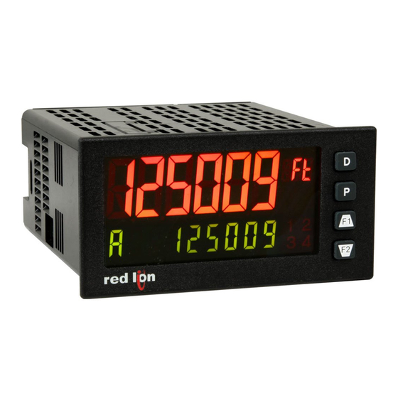
MODEL PAX2D – 1/8 DIN DIGITAL INPUT PANEL METER
DESCRIPTION
The PAX2D Digital Panel Meter offers many features and performance
capabilities that are not available on standard panel meters. The basic meter is a
dual counter and dual rate meter all in the same package. A third counter and
third rate display allows the user to do simple math functions. The optional plug-
in output cards allow the opportunity to configure the meter for present
applications, while providing easy upgrades for future needs.
Highlighting the PAX2D is a dual line, display with a large 0.71" tri-color 6
digit top display line and a 0.35", 9 digit green bottom display line. The meter
also offers programmable units display providing capability to tag the display to
the units of measure. Display color change capability provides machine
operators a visual indication of changing conditions, even when the operator is
not close enough to read the actual display value. In addition, a universal power
supply provides the ultimate in flexibility for both AC and DC inputs.
The meter accepts digital inputs from a variety of sources including switch
contacts, outputs from CMOS or TTL circuits, magnetic pickups and all
standard RLC sensors. The meter can process directional, uni-directional or
Quadrature signals simultaneously. The meter accepts input signals up to 50
KHz maximum depending on the count mode and function configurations
programmed. Each input signal can be independently scaled to various process
values.
The meter provides a MAX and MIN rate reading memory with programmable
capture time. The capture time is used to prevent detection of false max or min
readings which may occur during start-up or unusual process events.
The meter has up to four setpoint outputs, implemented on plug-in option
cards. The plug-in cards provide dual FORM-C relays, quad FORM-A, or either
quad sinking or quad sourcing open collector logic outputs. The setpoint alarms
can be configured to suit a variety of control and alarm requirements.
The PAX2 can be programmed to utilize Modbus protocol. With Modbus, the
user has access to most configuration parameters. Readout values and setpoint
alarm values can be controlled through the bus. Additionally, the meter has a
feature that allows a remote computer to directly control the outputs of the
meter. Communication and bus capabilities are also available as option cards.
These include RS232, RS485, DeviceNet, and Profibus-DP.
DIMENSIONS In inches (mm)
1.95
(49.53)
3.80 (96.52)
Note: Recommended minimum clearance (behind the panel) for
mounting clip installation is 2.1" (53.4) H x 5.5" (140) W.
1
2
3
4
0.10
(2.54)
COUNT, DUAL COUNTER WITH MATH FUNCTIONS
RATE, DUAL RATE WITH MATH FUNCTIONS
SLAVE DISPLAY
UNIVERSAL AC/DC POWER SUPPLY
6 / 9 DIGIT DUAL LINE/TRI-COLOR DISPLAY WITH 0.71" & 0.35"
DIGITS
10 POINT RATE SCALING FOR NON-LINEAR PROCESSES
PROGRAMMABLE UNITS DISPLAY
BUS CAPABILITIES; DEVICENET, MODBUS, AND PROFIBUS-DP
BUILT-IN USB PROGRAMMING PORT ENABLING UNIT
CONFIGURATION WITH CRIMSON PROGRAMMING SOFTWARE
NEMA 4X/IP65 SEALED FRONT BEZEL
The PAX2 includes a built-in USB programming port. With a Windows
based program, made available by Red Lion Controls, configuration data can be
downloaded to the PAX2 without the need of any additional option cards.
A linear DC output signal is available as an optional plug-in card. The card
provides either 20 mA or 10 V signals. The output can be scaled independent of
the input range and can track any of the counter, rate, max or min displays, or
any setpoint value.
Once the meter has been initially configured, the parameter programming
may be locked out from further modification in its entirety, or only selected
values can be made accessible for quick entry.
The meter has been specifically designed for harsh industrial environments.
With NEMA 4X/IP65 sealed bezel and extensive testing of noise effects and CE
requirements, the meter provides a tough reliable application solution.
SAFETY SUMMARY
All safety related regulations, local codes and instructions that appear in this
literature or on equipment must be observed to ensure personal safety and to
prevent damage to either the instrument or equipment connected to it. If
equipment is used in a manner not specified by the manufacturer, the protection
provided by the equipment may be impaired. Do not use this unit to directly
command motors, valves, or other actuators not equipped with safeguards. To do
so can be potentially harmful to persons or equipment in the event of a fault to
the unit.
CAUTION: Risk of Danger.
Read complete instructions prior to
installation and operation of the unit.
1.75
(44.45)
4.14 (105)
1
Bulletin No. PAX2D-A
Drawing No. LP0872
Released 01/12
®
CAUTION: Risk of electric shock.
3.60 (91.44)
Advertisement
Table of Contents

Related Manuals for red lion PAX2D


Summary of Contents for red lion PAX2D
-
Page 1: Safety Summary
Once the meter has been initially configured, the parameter programming Highlighting the PAX2D is a dual line, display with a large 0.71" tri-color 6 may be locked out from further modification in its entirety, or only selected digit top display line and a 0.35", 9 digit green bottom display line. -
Page 2: Table Of Contents
Ordering Information ....2 PAX2D Display Loops ....9 General Meter Specifications . -
Page 3: General Meter Specifications
ENERAL ETER PECIFICATIONS 1. DISPLAY: Negative image LCD 12. ENVIRONMENTAL CONDITIONS: Top Line - 6 digit, 0.71" (18 mm), with tri-color backlight (red, green or Operating Temperature Range: 0 to 50 °C orange), display range: -199,999 to 999,999; Storage Temperature Range: -40 to 60 °C Bottom Line - 9 digit, 0.35"... -
Page 4: Optional Plug-In Cards
These plug-in cards include: Adding Option Cards The PAX2D meters can be fitted with up to three optional plug-in cards. The PAXCDS10 - Dual Relay, FORM-C, Normally open & closed details for each plug-in card can be reviewed in the specification section below. -
Page 5: Installing The Meter
Installation Installation Environment The PAX2D meets NEMA 4X/IP65 requirements when properly installed. The unit should be installed in a location that does not exceed the operating The unit is intended to be mounted into an enclosed panel. Prepare the panel temperature and provides good air circulation. -
Page 6: Installing The Plug-In Cards
These cards plug into the main circuit board of the meter. The 1. With the meter removed from the case, locate the plug-in card connector for plug-in cards have many unique functions when used with the PAX2D. the card type to be installed. The types are keyed by position with different main circuit board connector locations. -
Page 7: Power Wiring
4.1 POWER WIRING AC Power DC Power AC/DC AC/DC AC/DC AC/DC AC/DC AC/DC 4.2 INPUT SIGNAL WIRING CAUTION: Sensor input common is NOT isolated from user input common. In order to preserve the safety of the meter application, the sensor input common must be suitably isolated from hazardous live earth referenced voltage;... -
Page 8: Front Panel Keys And Display Overview
4.3 USER INPUT WIRING If User Input 1 and/or 2 are wired for quadrature or directional counting, an additional switching device should not be connected to that User Input terminal. User Input terminal does not need to be wired in order to remain in inactive state. Sinking Logic (USrACt LO) Sourcing Logic (USrACt HI) USER INPUTS... -
Page 9: Pax2D Display Loops
LINE 2 DISPLAY LOOPS The PAX2D offers three display loops to allow users quick access to needed Main Display Loop information. In the Main Display Loop, the D key is pressed to sequence through the selected Line 2 values. A left justified 2 or 3-character mnemonic indicates which Line 2 value is currently shown. - Page 10 simultaneously. The next digit to the left will be selected (flashing). If both keys PROGRAMMING TIPS are pressed and held, the selected digit will scroll from right to left until one or It is recommended to start with the Input Parameters and proceed through both keys are released.
- Page 11 Counter B Selections COUNTER SCALE MULTIPLIER SELECTION MODE DESCRIPTION SCALEr None Does not count. NONE 0. 1 0. 0 1 Batch Counter B internally counts the number of output bAtCH activations of the selected setpoint(s). The count The number of input counts for the selected counter is multiplied by the scale source is selected in the Yes/No sub-menu shown multiplier and the scale factor to obtain the desired process value.
- Page 12 SCALING CALCULATION Each counter has the ability to scale an input signal to a desired display value. General Rules on Scaling This is accomplished by the counter mode (Cnt x), decimal point (dEC Pt), scale 1. It is recommended that, the scale factor be as close as possible to, but not factor (SC FAC), and scale multiplier (SCALEr).
- Page 13 Non-linear Application – Up to 10 Scaling Points RATE LOW CUT-OUT For non-linear processes, up to 10 scaling points may be used to provide a LO-CUt piece-wise linear approximation representing the non-linear function. The Rate 999999 Display will be linear between sequential scaling points. Thus, the greater the number of scaling points, the greater the conformity accuracy.
- Page 14 RATE C DISPLAY MULTIPLIER SCALEr 1000 Set the Display Multiplier to obtain the desired Rate C display resolution. For Rate C percentage calculations, the result is internally multiplied by 100 to show percent as a whole number. By using a Display Multiplier of 10, 100 or 1000, along with the proper decimal point position, percentage can be shown in tenths, hundredths or thousandths respectively.
- Page 15 USER INPUT/FUNCTION KEY PARAMETERS ( USEr This section details the programming for the rear terminal User Inputs and front panel Function Keys. Three user inputs are individually programmable to perform specific meter control functions. While in the Display Mode, the function is executed when the user input transitions to the active state. (Refer to the user input specifications for active state response times.) Certain User input functions are disabled in Programming Mode.
- Page 16 YES in the sublist. Both the STORE AND RESET DISPLAY Print and Reset actions will only function when the serial type parameter (tYPE) USEr-n is set to Red Lion protocol (rLC). DISPLAY DESCRIPTION FACTORY...
- Page 17 SETPOINT OUTPUT PARAMETERS (SEtPNt) This section details programming for the Setpoint (alarm) outputs. To have setpoint outputs, a setpoint Plug-in card needs to be installed into the PAX2D (see Ordering Information). Depending on the card installed, there will be two or four setpoint outputs available. For maximum input frequency, unused setpoints should be configured for NO action.
- Page 18 SETPOINT SELECT SETPOINT ANNUNCIATOR SELECt Annun FLASH OFF disables display setpoint annunciators. Normal (NOr) displays the Select the Setpoint output to be programmed. The “Sn” in the following corresponding setpoint annunciators of ON alarm outputs. Reverse (rEU) parameters will reflect the chosen setpoint number. After the chosen setpoint is displays the corresponding setpoint annunciators of OFF alarm outputs.
- Page 19 SETPOINT HYSTERESIS SETPOINT OUTPUT RESET WITH COUNTER RESET HYSt rESEt 59999 YESs The hysteresis value is added to (for tYPE = LO-ACt), or subtracted from (for Selecting YES causes the Setpoint output to deactivate (reset) when the tYPE = HI-ACt), the setpoint value to determine at what value to deactivate the Setpoint Assigned Counter is reset.
- Page 20 HIGH ACTING WITH DELAY HIGH ACTING WITH TIMEOUT LOW ACTING WITH DELAY LOW ACTING WITH TIMEOUT ANALOG OUTPUT PARAMETERS (ANALOG) This section is only accessible with the optional PAXCDL Analog card installed (see Ordering Information). OUtPUt tYPE ASSIGN LO-SCL HI-SCL ANALOG 4-20 NONE...
- Page 21 (dISPLY) ISPLAY ARAMETERS DISPLAY LINE SELECT dISPLY LINE 1 LINE 2 LINE 1 Select the Display Line to be programmed. LINE 1 PARAMETERS (LINE 1) This section details programming for the Line 1 (Top Line) Display. The Counter values, Rate values and the Maximum (Hi) and Minimum (Lo) Rate Capture values can be shown on the Line 1 display.
- Page 22 LINE 2 PARAMETERS (LINE 2) This section details programming for the Line 2 (Bottom Line) Display. The Counter values, Rate values, Rate Capture values, Setpoint values and Parameter List A/B status can all be shown on the Line 2 display. The Display Loops described below are used to view, reset and modify the selected display values, based on the Line 2 Value Access setting programmed for each available value.
- Page 23 LINE 2 DISPLAY SCROLL ENABLE/TIME PROGRAMMING SECURITY CODE ScroLL COdE seconds If Line 2 Display Scrolling is desired, set the scroll time in seconds. To activate either the Parameter or Hidden Parameter Display Loops, a security code (1-250) must be entered. If a “0” security code is programmed, pressing the P key takes you directly to the Full Programming Mode.
- Page 24 Following a Modbus command or RLC Transmit Value command, the PAX2D will wait this minimum amount of time in seconds before issuing a serial response Select either 7 or 8 bit data word lengths. Set the word length to match the...
-
Page 25: Serial Communications
The PAX2D supports serial communications using the optional serial communication cards or via the USB programming port located on the side of the unit. When USB is being used (connected), the serial communication card is disabled. When using the standard RS232 and RS485 Pax option cards, the PAX2D supports both the RLC protocol and also supports Modbus communications. -
Page 26: Pax2D Modbus Register Table
Values less than 65,535 will be in (Lo word). Values greater than 65,535 will continue into (Hi word). Negative values are represented by two’s complement of the combined (Hi word) and (Lo word). Note 1: The PAX2D should not be powered down while parameters are being changed. Doing so may corrupt the non-volatile memory resulting in checksum errors. REGISTER... - Page 27 REGISTER FACTORY REGISTER NAME LOW LIMIT HIGH LIMIT ACCESS COMMENTS ADDRESS SETTING 40051 40091 Counter B Scale Factor (Hi word) 999999 100000 Read/Write 1 = 0.00001 (decimal point fixed) 40052 40092 Counter B Scale Factor (Lo word) 40053 40093 Counter C Scale Factor (Hi word) 999999 100000 Read/Write 1 = 0.00001 (decimal point fixed)
- Page 28 REGISTER FACTORY REGISTER NAME LOW LIMIT HIGH LIMIT ACCESS COMMENTS ADDRESS SETTING Rate B 40201 Rate B Enable Read/Write 0 = No, 1 = Yes 40202 Rate B Decimal Point Read/Write 0 = 0, 1 = 0.0, 2 = 0.00, 3 = 0.000, 4 = 0.0000 40203 Rate B Low Cut-Out Value (Hi word) 999999...
- Page 29 REGISTER FACTORY REGISTER NAME LOW LIMIT HIGH LIMIT ACCESS COMMENTS ADDRESS SETTING OUTPUT PARAMETERS SEE OUTPUT MODULE FOR PARAMETER DESCRIPTIONS Setpoint 1 0 = None, 1 = Counter A, 2 = Counter B, 3 = Counter C, 4 = 40291 Assignment Read/Write Rate A, 5 = Rate B, 6 = Rate C...
- Page 30 REGISTER FACTORY REGISTER NAME LOW LIMIT HIGH LIMIT ACCESS COMMENTS ADDRESS SETTING 40346 Output Reset with Counter Reset Read/Write 0 = No, 1 = Yes 40347 Output Reset at Sn+1 Read/Write 0 = No, 1 = Reset at Sn+1 Start, 2 = Reset at Sn+1 End Setpoint 4 0 = None, 1 = Counter A, 2 = Counter B, 3 = Counter C, 40351...
- Page 31 REGISTER FACTORY REGISTER NAME LOW LIMIT HIGH LIMIT ACCESS COMMENTS ADDRESS SETTING 40406 Line 2 Units Mnemonic Digit 3 Read/Write 40407 Line 2 Units Mnemonic Digit 4 Read/Write 40408 Line 2 Units Mnemonic Digit 5 Read/Write 40409 Line 2 Units Mnemonic Digit 6 Read/Write 40410 Line 2 Units Mnemonic Digit 7...
- Page 32 REGISTER FACTORY REGISTER NAME LOW LIMIT HIGH LIMIT ACCESS COMMENTS ADDRESS SETTING 0 = No Display, 1 = Count A, 2 = Count B, 3 = Count C, 4 = 40504 Line 1 Display (Top Line) Read/Write Rate A, 5 = Rate B, 6 = Rate C, 7 = Max (Hi), 8 = Min (Lo) 0 = No Display, 1 = Count A, 2 = Count B, 3 = Count C, 4 = 40505 Line 2 Display (Bottom Line)
- Page 33 REGISTER FACTORY REGISTER NAME LOW LIMIT HIGH LIMIT ACCESS COMMENTS ADDRESS SETTING 40643 40843 Counter A Mnemonic - Digit 7 Read/Write 40644 40844 Counter A Mnemonic - Digit 8 Read/Write 40645 40845 Counter A Mnemonic - Digit 9 (Right) Read/Write 40646 40846 Counter B Mnemonic - Digit 1 Read/Write 40647 40847 Counter B Mnemonic - Digit 2...
- Page 34 ACCESS COMMENTS ADDRESS SETTING 40708 40908 Min (Lo) Mnemonic - Digit 9 Read/Write RLC-PAX2D <a><b><0100h><0040h><0040h><0010h> <a> = SP Card Status. "0"-No Card, "2"-Dual SP, "4"-Quad SP <b> = Linear Card Status. "0"-Not Installled, "1"-Installed 41001-41010 Slave ID Read Only <0100h> = Version Number (1.00 or higher) <0040h><0040h>...
- Page 35 When a string that does not begin with #, T, V, P or R is received, the meter Downloading Data from a G3 to a PAX2D processes it as a Numeric transmission. In this case, only numbers and a minus Communications: sign can be displayed.
- Page 36 COMMAND RESPONSE TIME Timing Diagrams The meter can only receive data or transmit data at any one time (half-duplex operation). When sending commands and data to the meter, a delay must be NO REPLY FROM METER imposed before sending another command. This allows enough time for the meter to process the command and prepare for the next command.
-
Page 37: Factory Service Operations
(active high) operation, the Input be calibrated. At each prompt, use the PAX2D and keys to adjust the Logic for Input A and/or Input B can be changed by entering Code 55. -
Page 38: Troubleshooting Guide
Linear Output Card Data Validation Error. Press any key to clear Error Code and cycle power. If Error EE Lin Code returns at next power-up, replace Linear Option Card or contact factory. PARAMETER VALUE CHART Programmer ________________ Date ________ PAX2D Meter# _____________ Security Code ________ INPUt INPUT SETUP PARAMETERS COUNt Counter Parameters... - Page 39 ANALOG Analog Output Parameters DISPLAY PARAMETER USER SETTING RbxdSP 3 Rate B Scaling Point 3 Display DISPLAY PARAMETER USER SETTING tYPE Rb INP 3 Analog Output Type Rate B Scaling Point 3 Input ASSIGN RbxdSP 4 Analog Output Assignment Rate B Scaling Point 4 Display LO-SCL Rb INP 4 Analog Low Scale Value...
- Page 40 dISPLY DISPLAY PARAMETERS UNItS Line 2 Units Mnemonic(s) LINE 1 Line 1 Parameters LABEL MNEMONIC LABEL DISPLAY PARAMETER USER SETTING List A List B Color Line 1 Display Color Unit 1 Line 2 Units Digit 1 (Left) d-LEV Display Level Unit 2 Line 2 Units Digit 2 d-Cont...
- Page 41 This page intentionally left blank.
-
Page 44: Limited Warranty
The Company disclaims all liability for any affirmation, promise or representation with respect to the products. The customer agrees to hold Red Lion Controls harmless from, defend, and indemnify RLC against damages, claims, and expenses arising out of subsequent sales of RLC products or products...
Need help?
Do you have a question about the PAX2D and is the answer not in the manual?
Questions and answers