
Related Manuals for Parker N2-160


Summary of Contents for Parker N2-160
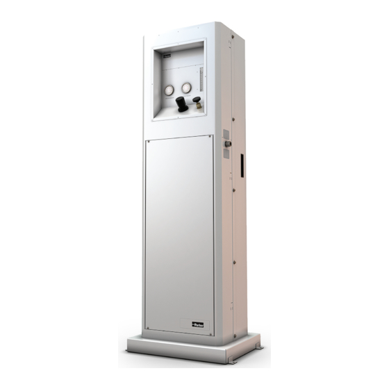
- Page 1 Nitrogen Generator Installation, Operation, & Maintenance Manual Models: N2-120, N2-160, N2-240...
- Page 2 INSTALLATION, OPERATION, AND MAINTENANCE MANUAL NITROGEN GENERATORS...
-
Page 3: Table Of Contents
INSTALLATION, OPERATION, AND MAINTENANCE MANUAL NITROGEN GENERATORS TABLE OF CONTENTS Page 1. WARRANTY ......................3 2. SAFETY PRECAUTIONS ...................4 3. GENERAL DESCRIPTION ..................5 4. ENGINEERED SYSTEM ....................5 4.1 Prefiltration .......................6 4.2. Air Separation ....................6 4.3 Final Filtration ....................6 4.4 Controls ......................6 5. -
Page 4: Warranty
Parker guarantees, at Parker’s option, to replace the product, repair the product, or refund the original price for the prod- uct. This warranty applies only to defects in material or workmanship and does not cover: ring and valve wear on compressors, routine maintenance recommended by the instructions provided with this product, or filter cartridges. -
Page 5: Safety Precautions
If you have any questions or concerns, please call the Technical Services Department at 1-800-343-4048, 8 AM to 5 PM Eastern Time or email at GSFsupport@parker.com. (North America only). For other locations, please contact your local representative. -
Page 6: General Description
110-115 psig (7.6-7.9 barg). 4. ENGINEERED SYSTEM The Parker N2-120, N2-160, and N2-240 Nitrogen Generators have been certified to IEC 1010 Standards (CSA 22.2 No. 61010-1-12). The generators bear the CSA safety marking on the product label. -
Page 7: Prefiltration
® incorporated into the Parker Nitrogen Generators to protect the membrane module from contamina- tion. The coalescing filters are located behind the filtration access panel. They remove liquids and particulate matter from the incoming air supply to 0.01 micron. -
Page 8: Oxygen Monitoring
If an oxygen analyzer is needed, Parker Model 72-730NA, which has built-in alarms for connection to external relays, may be used. This oxygen analyzer has all the controls necessary to assure safe and accurate monitoring of the oxygen concentration in a process stream. -
Page 9: General
The inlet and outlet ports on the nitrogen generators are 1/2" female NPT. A 1/2" male connector which will withstand 145 psig (10 barg) should be used to connect to the nitrogen generator. Parker offers an installation kit (P/N IK75880) which combines all the basic fittings and refrigeration grade copper tubing required to bring the system online. -
Page 10: Location
30% to 40% oxygen permeate stream which may pose a flammability risk in an oxygen sensitive environment. 6.4 Utilities Compressed Air - The Parker Nitrogen Generators require a source of compressed air at room temperature and relatively free of water, compressor oil, hydrocarbons, and particulate matter. An oil content <0.01 mg/m is recommended. -
Page 11: Installation With A Receiver Tank
If a receiver tank is to be used, a back pressure regulator and a check valve should be installed between the Parker Nitrogen Generator and the receiver tank (see Figure 5). The Balston 72-460- V883 Back Pressure Controller contains both components and may be ordered as an accessory for the Nitrogen Generator. -
Page 12: Operation
7. OPERATION 7.1 Startup The inlet and outlet connections to the Parker Nitrogen Generator must be checked for leaks prior to system start-up. After the system is properly installed and checked for leaks, the inlet gate valve can be slowly opened to introduce compressed air to the system. -
Page 13: Nitrogen Flow At Given Operating Pressure And Purity
1. On the generator, the flow meter units are dimensionless. For N2-160 & N2-240, read flowmeter at the middle of the ball. For N2-120, read flow meter at the top of the ball. The actual flow at various operating pressures is converted into standard liters per minute (SLPM) in the purity label on the unit. - Page 14 95.00 Model N2-160 60 PSIG 70 PSIG 80 PSIG 90 PSIG 100 PSIG 125 PSIG 145 PSIG Purity Meter SLPM Meter SLPM Meter SLPM Meter SLPM Meter SLPM Meter SLPM Meter SLPM 99.50 99.00 98.00 97.00 96.00 95.00 Model N2-120...
-
Page 15: Operation - Adjustment Procedures
98.00 97.00 96.00 95.00 Model N2-120 9. OPERATION - ADJUSTMENT PROCEDURES 9.1 Atmospheric Pressure Applications (<10 psig / 0.7 barg) If the Nitrogen Generator is being used to deliver nitrogen at or near atmospheric pressure (e.g. purging or blanketing applications), use the following procedure for start-up and adjustment of the system. -
Page 16: Elevated Pressure Applications (>10 Psig)
INSTALLATION, OPERATION, AND MAINTENANCE MANUAL NITROGEN GENERATORS 6. Allow the system to reach equilibrium at the desired flow rate, pressure, and purity parame- ters. This should take approximately 15 minutes. Vent substandard nitrogen if necessary (see Figure 4). 7.. Check the purity readings on the oxygen analyzer on a routine basis. If nitrogen purity falls below the desired level, check the calibration of the oxygen analyzer, and readjust the flow control valve until the proper nitrogen purity level is reached. -
Page 17: Receiving Tank Applications
(see Steps 3 through 7 above) each time the unit is started. 9.4 Temperature Equilibrium If the temperature of the inlet air to the Parker Nitrogen Generator differs from the temperature of the module (i.e. ambient temperature), the system must be allowed to reach thermal equilibrium before a nitrogen stream of consistent purity can be delivered from the system. -
Page 18: Evaluation
NITROGEN GENERATORS 9.5 Evaluation Performance of the Parker Nitrogen Generator is highly dependent on the temperature of the inlet air. The data on the flow rate presented in this bulletin is based on an inlet air temperature of 77^F (25^C). -
Page 19: Cleaning
INSTALLATION, OPERATION, AND MAINTENANCE MANUAL NITROGEN GENERATORS 10.1 Cleaning This product is not intended for use in extremely dirty environments. The Nitrogen Generators may be wiped clean with a dry cloth on an as needed basis. Do not use water, aerosols, or other cleaning agents to clean the unit. -
Page 20: Activated Carbon Filter Replacement
The carbon filter is located behind the filtration access panel. Contact the local Parker representative for ordering information and pricing for a replacement carbon filter. Spent carbon towers may be disposed of locally by the user. -
Page 21: Nitrogen Generation System Specifications
INSTALLATION, OPERATION, AND MAINTENANCE MANUAL NITROGEN GENERATORS 11. NITROGEN GENERATION SYSTEM SPECIFICATIONS Model Number N2-120, N2-160, N2-240 Purity Range (% Nitrogen) 99.0-99.5 CSA Certification Standard CSA 222 No. 61010.1-12 (IEC 1010) IEC 1010 Installation Category Category II IEC 1010 Pollution Degree... -
Page 22: Optional Accessories
75478 11.3 Cautions 1. The Parker Membrane Nitrogen Generators should be installed in an area with adequate ventilation to reduce the flammability of the oxygen-rich permeate stream. The system should not be located in an area where the permeate stream poses the risk of explosion or combustion. -
Page 23: Troubleshooting
If leak persists, replace automatic float drain (P/N 21552). If issue remains unresolved, please call the Technical Services Department at 1-800-343-4048, 8 AM to 5 PM Eastern Time or email at GSFsupport@parker.com (North America only). For other locations, please contact your local representative. - Page 24 419 644 4311 Arnhem, Netherlands +31 (0) 26 376 0376 © 2022 Parker Hannifin Corporation. Product names are trademarks or registered trademarks of their respective companies. Bulletin TI-N2-120 Rev. A 032022 Parker Hannifin Corporation Industrial Gas Filtration and Generation Division...
Need help?
Do you have a question about the N2-160 and is the answer not in the manual?
Questions and answers