
Related Manuals for Parker NitroFlow Basic Series


Summary of Contents for Parker NitroFlow Basic Series
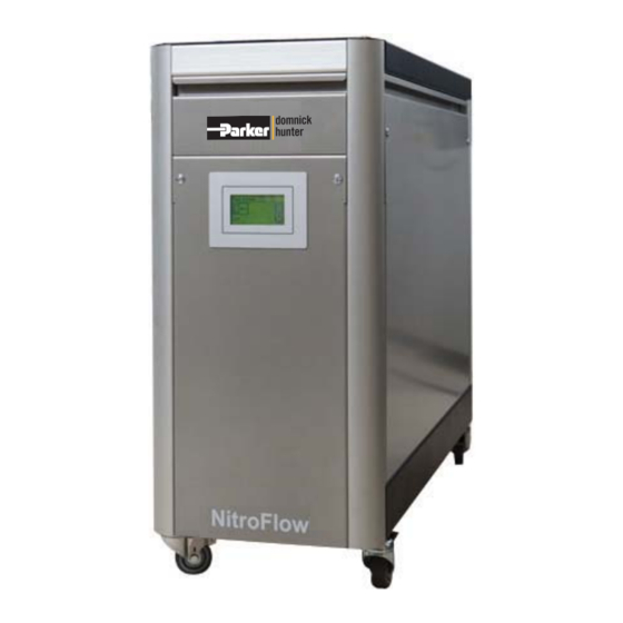
- Page 1 aerospace Nitrogen Gas Generator climate control electromechanical ® NitroFlow Basic filtration fluid & gas handling User Guide hydraulics pneumatics Original Language process control sealing & shielding...
- Page 2 Parker. Parker retains the right to make changes in parts at any point without first or directly notifying the customer. The contents of this manual can also be changed without prior warning.
-
Page 3: Table Of Contents
INTRODUCTION ..............................4 General ................................4 Pictograms ..............................4 Use in accordance with purpose ........................5 User instructions .............................5 Liability................................5 HEALTH, SAFETY AND ENVIRONMENTAL ASPECTS ..................6 General ................................6 Nitrogen and oxygen ............................6 Electricity ................................6 Safety precautions ............................6 Environmental aspects ...........................7 DESCRIPTION OF THE APPLIANCE ........................8 General ................................8 Separation principle ............................8 Parts ................................9... - Page 4 TROUBLESHOOTING ............................28 Error list ................................28 Alarm messages ..........................28 MAINTENANCE ..............................30 Maintenance schedule ..........................30 Calibrate oxygen sensor..........................30 Cleaning ...............................30 ELECTRICAL SCHEME ..........................31 DECLARATION OF CONFORMITY .......................32 K3.1.114o Manual NitroFlow Mobile - 3 -...
-
Page 5: Introduction
All information in this manual, including additional drawings and technical descriptions, remains the property of Parker and may not be used (otherwise than for the use of this product), copied, multiplied or published to or for a third party without explicit prior written permission by Parker. -
Page 6: Use In Accordance With Purpose
Basic Mobile is intended to produce nitrogen out of normal ambient air. The system is based on gas separation membranes. Each different or further use will not be in conformity with the purpose. Parker will not accept any liability for improper use. -
Page 7: Health, Safety And Environmental Aspects
Contact your supplier if you detect a problem that you cannot solve with this manual. Use the generator in accordance with its purpose. Refer to §1.3. Only competent personnel trained, qualified and approved by Parker Industrial Division are allowed to perform installation, commissioning, service and repair procedures. -
Page 8: Environmental Aspects
According to EC-regulations electrical systems have to be disassembled and recycled at the end of their life. Parker can support you in this. Make sure that instructions concerning health, safety and environment are compliant with the local legislation and regulations. -
Page 9: Description Of The Appliance
Description of the appliance General The generator separates compressed air produced by an on-board compressor into nitrogen and an oxygen enriched air stream. The separation system is based on membranes. Separation principle H2O - H2 Fig. 3-1: Separation principle Pressurised air inlet Fast permeation Hollow fibre membrane Slow permeation... -
Page 10: Parts
Parts Removable Front Cover Main Switch / Circuit Breaker Oxygen Sensor Electrical Supply Cable Inlet Pressure Control Valve (PCV) Nitrogen Outlet Purity Adjustment Valve (FCV) Ventilation Outlet (Keep Clear) Touch Screen Display Process diagram The generator can be connected directly to the nitrogen consumer (Fig. 3-3) or to a buffer vessel (Fig. 3-4). Nitrogen ®... -
Page 11: Process Scheme
Process scheme ® 3.5.1 NitroFlow Basic Mobile HP Air inlet Nitrogen outlet Inlet carbon adsorber Air compressor Start-up valve Gas separation membrane Membrane pressure indicator Flow control valve Nitrogen compressor Nitrogen pressure relief valve Pressure switch Nitrogen pressure indictor Non-return valve Nitrogen outlet Ball valve Depressurisation valve... -
Page 12: Nitroflow Basic Mobile Lp
® 3.5.2 NitroFlow Basic Mobile LP Air inlet Nitrogen outlet Inlet carbon adsorber Air compressor Start-up valve Gas separation membrane Membrane pressure indicator Flow control valve Nitrogen pressure relief valve Pressure switch Nitrogen pressure indicator Non-return valve Nitrogen outlet Ball valve K3.1.114o Manual NitroFlow Mobile - 11 -... -
Page 13: Technical Specifications
Technical specifications General Delivery pressure Maximum delivery pressure Low Pressure (LP): 2 bar(g) / 29 psig High Pressure (HP): 8 bar(g) / 116 psig Ambient conditions Temperature 5 to 40 °C / 41 to 104 °F Humidity 50% @ 40°C (104°F) (80% MAX < 31°C (87.8°F)) IP Rating IP20 / NEMA 1 Pollution Degree... - Page 14 Default software settings Menu What Default setting Delay-time 180 sec Logs Language English Local settings Pressure Local settings Flow Local settings Purity Local settings O2 high Active: No Alarm settings Stop: 0 Level: 5 Delay: 30 O2 low Active: No Alarm settings Stop: 0 Level: 0.0...
-
Page 15: Capacity Data
Parts Generator ® NitroFlow Basic Mobile Manual Storage vessel Options (on demand) ® ® Vac/Hz NitroFlow Basic Mobile LP NitroFlow Basic Mobile HP 120 / 60 159.003727 159.003364 230 / 50 159.003728 159.003340 Capacity data Generator Nominal production capacity Nlpm* Purity% 99.9 99.7... -
Page 16: Installation
Installation Follow the paragraphs in this chapter to install the generator. Transport Warning Transport the generator upright. Put the generator in the original box to transport the generator over longer distances. Lift the generator with a forklift. For qualifications of personnel, refer to §2.1. Define location IMPORTANT The generator contains compressors that generate heat;... -
Page 17: Connect Input And Output Signals
Connect input and output signals Input and output signals can be connected to the terminal strip on the printed circuit board. Clamp Function Input/output signals Remote start/stop Digital input Nominal input current: 10 mA Voltage: internal power supply Oxygen concentration Analogue output Input impedance to reach Outlet pressure... -
Page 18: Operation Of The Control System
Operation of the control system Menu structure The menu structure of the control system is built up as shown below. One can always go back to a higher level in -button. the menu by pushing the Main screen Alarm Settings Switch on/off unit display Log on... -
Page 19: Settings Menu
When the unit is switched on the controller will show: Actual outlet pressure Actual oxygen or nitrogen level Flow indication (when selected, refer to §6.3.4) Settings menu Access: Touch settings menu button in the main screen (refer to §6.2) Function: Access to different menus Symbol Menu... -
Page 20: Log On Menu
6.3.1 Log on menu Access: Touch log on menu button in settings screen (refer to §6.3) ATTENTION: When you start-up the system for a first time you do not need to enter a PIN CODE Function: Protect the settings in the system with a (personal) pin code. In the log on menu: Enter the default pin code (1234) after selecting PINCODE YES under the options menu (refer to §6.3.4). - Page 21 Button Selection Result Active Alarm function for this parameter is not active Active Alarm function for this parameter is active; alarm messages must be reset manually Active Auto reset Alarm function for this parameter is active; When alarm level is not exceeded any longer before manual reset, the alarm will reset itself Stop...
-
Page 22: Pressure Switch Menu
6.3.3 Pressure switch menu Access: Touch pressure switch menu button in settings screen (refer to § 6.3) Function: Set the pressure switch In the pressure switch menu the levels at which outlet pressure the generator will switch on and off, can be set. To change the settings, touch the button in front of the text. -
Page 23: Options Menu
6.3.4 Options menu Access: Press option menu button in settings screen (refer to §6.3) Function: Set different options ATTENTION: All options are default set to NO. Options do not affect the output and purity. Button Selection Result Auto R. After a power failure the unit will automatically restart itself and return to the same situation/status. -
Page 24: Maintenance Menu
Button Selection Result Language English, Francais, Deutsch, Text in the screen will appear in the chosen Nederlands, Español language. Pressure BAR/PSI* Pressure indications will appear in the chosen setting Flow LPM/CFM Flow will appear in the chosen setting Purity %N2/%O2 Purity will appear in nitrogen (%N2) or oxygen (%O2) percentage * Select BAR, to display temperature in °C. - Page 25 Button Explanation O2 – 20.9% Calibrate O sensor to 20.9%. Contact Parker’s technical support team. Flow Factor Only visible when selected Show Flow in the options menu (refer to §6.3.4) and when the unit is running. Calibrate the flow by entering the flow measured with an external flow meter.
-
Page 26: Data Logging Menu
Replace O2 cell When an O cell has been replaced during maintenance, this button can be touched and a new date to replace the O cell is set. System asks for confirmation. In maintenance screen 1/5 the O lifetime should read 3 year ahead from date of changing. -
Page 27: Operation
Operation Commissioning generator 1. Make sure that the connections are correct and fixed properly. 2. Switch on the generator with the switch at the back of the generator (refer to §3.3). 3. Then touch the ON/OFF button on the touch screen display in the front of the generator. CAUTION Don’t use sharp objects to operate the screen. -
Page 28: Control Of The Outlet Pressure
ATTENTION The response time of the measurement is slow. Change the flow in small steps of a quarter turn per step and wait until the display reading changes. Do not close the flow control valve fully. Adjusting the purity must preferably be done when the system is at normal operating temperature after it has run for some time (1-2 hrs) Adjusting the purity must be done while all sheet metal is mounted on the appliance 5. -
Page 29: Troubleshooting
Check whether the minimum clearance between the generator and the walls is large enough Inlet carbon adsorber filter is polluted Contact Parker for service generator is switched off Switch on the generator Leak in piping Check for leaks in the piping... - Page 30 What happens Alarm description Default Oxygen level too high O2 high Oxygen level too low O2 low Inlet pressure too high P-inlet high Inlet pressure too low P-inlet low Outlet pressure too high P-outlet high Outlet pressure too low P-outlet low Inlet temperature too high T-inlet high Inlet temperature too low...
-
Page 31: Maintenance
Maintenance Maintenance schedule Part Action Frequency 1x per year Filters Replace carbon adsorber 1x per 3 years Oxygen sensor Replace oxygen sensor 1x per 3 months Oxygen sensor Calibrate oxygen sensor Table 9-1: Maintenance schedule Calibrate oxygen sensor 1. Remove the sensor cap (E) and expose the sensor to ambient air. 2. -
Page 32: Electrical Scheme
Electrical scheme K3.1.114o Manual NitroFlow Mobile - 31 -... -
Page 33: Declaration Of Conformity
Declaration of Conformity K3.1.114o Manual NitroFlow Mobile - 32 -... - Page 34 NOTES...
- Page 36 (from AT, BE, CH, CZ, DE, DK, EE, ES, FI, FR, IE, IL, IS, IT, LU, MT, NL, NO, PL, PT, RU, SE, SK, UK, ZA) © Parker Hannifin Corporation. All rights reserved. Catalogue: K3.2.114 Parker Hannifin Manufacturing ltd 04/13 Rev: o...
Need help?
Do you have a question about the NitroFlow Basic Series and is the answer not in the manual?
Questions and answers