Table of Contents
Advertisement
Bulletin TI-H2PEMPD-D
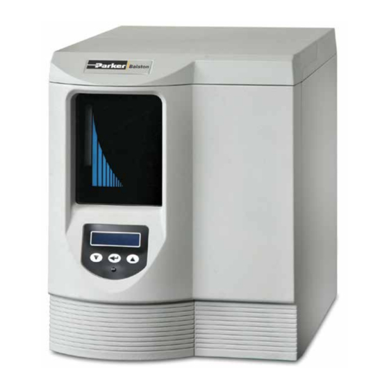
Parker Hydrogen Gas Generator
Models H2PEMPD-510, H2PEMPD-650,
H2PEMPD-850, H2PEMPD-1100, H2PEMPD-1300
Installation, Operation, and Maintenance Manual
1-800-343-4048
Installation, Operation and Maintenance Manual
Hydrogen Gas Generator H2PEMPD Series
1
www.parker.com/fns/balstonlabgenerators
Advertisement
Chapters
Table of Contents

Related Manuals for Parker H2PEMPD-510


Summary of Contents for Parker H2PEMPD-510
- Page 1 Installation, Operation and Maintenance Manual Bulletin TI-H2PEMPD-D Hydrogen Gas Generator H2PEMPD Series Parker Hydrogen Gas Generator Models H2PEMPD-510, H2PEMPD-650, H2PEMPD-850, H2PEMPD-1100, H2PEMPD-1300 Installation, Operation, and Maintenance Manual 1-800-343-4048 www.parker.com/fns/balstonlabgenerators...
- Page 2 Bulletin TI-H2PEMPD-D Hydrogen Gas Generator H2PEMPD Series Parker Balston Technical Information Bulletin Please note that all Parker gas generators have a warranty period of 1 year from the date of shipment WARNING! The H2PEMPD-1300 hydrogen generator, operating at full flow, will consume the entire water reservoir volume in approximately 60 hours.
- Page 3 Hydrogen Gas Generator H2 PEMPD series Warranty This warranty applies to the generator and associated parts (the equipment) manufactured and supplied by Parker Hannifin Corporation, Filtration Separation Division (the company). Use of the generator without the recommended water quality or genuine parts will expressly invalidate the warranty. Any modification of the generator will void the warranty.
-
Page 4: Table Of Contents
5.3.2 Replacing the deionizer cartridge and 100 micron water filter ….................19 5.3.3 Replacing the Environmental Filters …........................19 5.3.4 Replacing the water pump…………………………………………………… ….................19 5.3.5 Replacing the fan guards………………. …........................21 5.3.6 Filling the water bottle…… ..........................21 6 Error Messages........................................20 1-800-343-4048 www.parker.com/balston... -
Page 5: Safety Information
If the user employs an operating procedure, item of equipment or a method of working which is not specifically recommended by Parker Hannifin the user must ensure that the equipment will not be damaged or become hazardous to persons or property. -
Page 6: Markings And Symbols
Bulletin TI-H2PEMPD-D Installation, Operation and Maintenance Manual Hydrogen Gas Generator H2 PEMPD series 1.1 Markings and Symbols The following markings and international symbols are used on the equipment or within this manual: Table 1 1-800-343-4048 www.parker.com/balston... -
Page 7: Description
In order to guarantee the optimum efficiency of the PEM cell, this generator must be installed and running within three months of dispatch from Parker Hannifin. Failure to do this may invalidate the warranty. The generator will perform a 60 minute (1 hour) initialization sequence when powered for the first time. - Page 8 Bulletin TI-H2PEMPD-D Installation, Operation and Maintenance Manual Hydrogen Gas Generator H2 PEMPD series Units H2PEMPD-510 H2PEMPD-650 H2PEMPD-850 H2PEMPD-1100 H2PEMPD-1300 Water Water Quality Deionized, ASTM II, > 1M ?, <1µS, Filtered to <100µm Consumption (Approximate) cc/week 4000 5000 7000 8000 9000 psi g 1.45...
-
Page 9: Weight And Dimensions
2.2 Receiving and Inspecting the Equipment On receipt of the equipment carefully inspect the packaging for damage. If the packaging is damaged inform the delivery company immediately and contact your local Parker Hannifin office. 2.3.1 Storage If the equipment is to be stored prior to installation, do not remove it from the packaging. Ensure that it is stored in an upright position as indicated by the arrows on the packaging Do not attempt to lift the generator by yourself. -
Page 10: Unpacking
1. Supplied only with generators fitted with the water fill option Table 4 If any items are missing or damaged please contact your local Parker Hannifin office. Do not attempt to power up the generator. 2.3.3 Overview of the equipment... -
Page 11: Environment
The generator should be connected to the supply using 1/4” PTFE tubing (1/4” PTFE supplied). Note. The automatic water fill system is available as a factory or field fit optional extra. Contact Parker Hannifin for further details. 2.4.5 Electrical Supply Requirements The equipment should be connected directly from the fused IEC 320 inlet socket to the electrical supply using the appropriate power cord supplied. -
Page 12: Installation & Setup
11417-1 Premium Copper Tubing 1/8" 11412-1 Premium Copper Tubing 1/4" Table 7 The installation kits shown in table 7 will allow for installations as shown in figure 3. Please contact your local Parker Hannifin office for more details. 1-800-343-4048 www.parker.com/balston... -
Page 13: Connecting The Generator
Check the rating plate for the correct supply voltage and frequency. Select the required power cord and connect it to the switched IEC 320 socket on the generator. Connect the plug directly to the electrical supply. Do not use an extension cord. 1-800-343-4048 www.parker.com/balston... -
Page 14: Filling The Water Bottle
The options board is designed for connection to Safe Extra Low Voltage (SELV) systems only. Maximum 12vdc 50mA. The options board accessory allows direct communication with a PC via the USB port, and connection of water monitoring, remote alarm, and remote stop circuits. For applications requiring load balancing, please contact your local Parker Hannifin office. 1-800-343-4048... -
Page 15: Wiring The Options Board
JP5 Water Fill Output – The water fill output allows for remote monitoring of the water bottle level. When the water level drops below the mid-point in the water bottle, this output activates an external water fill system. 1-800-343-4048 www.parker.com/balston... -
Page 16: Starting Up The Generator
In order to guarantee the optimum efficiency of the PEM cell, this generator must be installed and running within three months of dispatch from Parker Hannifin. Failure to do this may invalidate the warranty. The generator will perform a 60 minute (1 hour) initialization sequence when powered for the first time. -
Page 17: Operating The Equipment
During start-up the generator may revert to the last error mode it experienced. If this occurs press . When the error is cleared the generator will continue with the startup procedure. If the error cannot be cleared by this method follow the fault finding procedure in section 6 of this user guide. 1-800-343-4048 www.parker.com/balston... -
Page 18: Operating Menus
During initial startup, all five blocks will be shaded indicating that the generator is building up pressure and not currently on line. When the generator is on-line and delivering gas to the application, the number of blocks shaded will depend upon the flow required by the application. 1-800-343-4048 www.parker.com/balston... -
Page 19: Conductivity
4.3.3 Pressure Measurement The units of pressure measurement may be changed between bar, psi and Mpa. Press to change the units of measurement. When the desired units have been selected, press to advance to the next menu 1-800-343-4048 www.parker.com/balston... -
Page 20: Run Time Data
Pressure release– All pressure within the generator is released. The test will not proceed until the generator is fully depressurized. Pressure build–The generator is pressurized to a maximum operating pressure of 100 or 175 psi g (6.89 or 12.06 bar g). The time taken to reach this pressure is monitored by the generator. 1-800-343-4048 www.parker.com/balston... -
Page 21: Hard Reset
5 If the generator is to be transported drain the water from the generator as described in section 6. Refit the hydrogen outlet port plug and the two transit plugs to the excess H2 vent and the water bottle vent. 1-800-343-4048 www.parker.com/balston... -
Page 22: Servicing
5 Servicing The recommended service procedures identified below, along with all other repair and calibration work should be undertaken by a Parker Hannifin approved engineer. 5.1 Cleaning Clean the equipment with a damp cloth only and avoid excessive moisture around any electrical sockets. If required you may use a mild detergent, however do not use abrasives or solvents as they may damage the warning labels on the equipment. -
Page 23: Service Kits
5.2.2 Recommended Service B - Required every 16000Hrs (24 months) Description Kit No. Contents 1. Deionizer cartridge 2. 100 micron water filter 3. Environmental filters (x2) Complete Service MKH2PEMPD-24M 4. Filter replacement tool 5. Tube clamp 6. Water pump 7. Fan guard (x2) Table 13 1-800-343-4048 www.parker.com/balston... -
Page 24: Consumable Replacement Procedures
Remove the two environmental filters (figure 18, item 3) from the vent ports by pushing the push in fitting upwards to release. Fit the replacement filters and check that they are secure. Note: Environmental filters should be changed every six months as there is no visual indication of exhausted filters. 1-800-343-4048 www.parker.com/balston... - Page 25 With all the water drained from the water reservoir, place some paper toweling in the bottom of the generator to catch any residual water within the tubes and water pump. As shown in figure 24, clamp the water pump inlet tube and remove the associated hardware. Fit the replacement pump and reconnect the wiring and tubing. 1-800-343-4048 www.parker.com/balston...
-
Page 26: Replacing The Fan Guards
LCD will display “Water Full” message. Once full replace the water bottle cap and top front cover. Note: If the water has been changed due to high conductivity, the deionizer cartridge must also be changed. Figure 25 1-800-343-4048 www.parker.com/balston... -
Page 27: Error Messages
INTERNAL LEAK Faulty H2 line internal Check all H2 line ACT 100% connection connections LOW PRESSURE Check/eliminate overflow ACT 100% Cell low pressure condition OVER RUN Generator/Cell operating Check/eliminate overflow ACT 100% at >100% capacity condition 1-800-343-4048 www.parker.com/balston... -
Page 28: Water Pump
CASE FAN FAIL Case cooling fan not Reset/replace the ACT 100% rotating external fan O2 FLOAT CONNECT Reservoir level sensor Reset/check connector, ACT 100% faulty replace sensor TEMP XDUCER Reset/check connector. ACT 100% Purifier temp sensor faulty Replace heater 1-800-343-4048 www.parker.com/balston... - Page 29 Replace heater SERVICE REQUIRED Perform service. Use ACT 100% Service time applicable kit O2 VENT BLOCK Reset/remove blockage & ACT 100% O2 vent is blocked Off(System lock) reset REMOTE STOP JP3 on options board ACT 100% Remove short/reset shorted 1-800-343-4048 www.parker.com/balston...
- Page 30 Keep your product certification in a safe place. Contact: Contact the Technical Services Department at 1-800-343-4048, 8AM to 5PM Eastern Time (North America only) or email at balstontechsupport@parker.com. For other locations, please contact your local representative or email at TSGIndustrial.Enquiries@parker.com.
Need help?
Do you have a question about the H2PEMPD-510 and is the answer not in the manual?
Questions and answers