Parker Oildyne 108 Series Instruction Manual

Parker Oildyne 108 Series Instruction Manual

Hydraulic power units
Table of Contents

Advertisement

Bulletin HY22-3210A/US
Instruction Manual
Effective: June 01, 2011
Oildyne 108/118
and 165/175 Series
Hydraulic Power Units
416180

Advertisement

Table of Contents
loading
Need help?

Need help?

Do you have a question about the Oildyne 108 Series and is the answer not in the manual?

Questions and answers

darrel staner
March 3, 2025

how do you hydrolic fluid in 108 645677 is manual available

1 comments:
Mr. Anderson
May 14, 2025

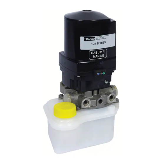
To add hydraulic fluid to the Parker 108 Series 645677:

1. Make sure the reservoir is filled before starting the power unit.
2. Use only approved fluids such as standard ATF or mineral-based hydraulic fluids with viscosity between 32 cSt and 64 cSt at 38°C (100°F).
3. Fill the reservoir through the filler cap/breather.
4. Ensure the fluid is clean and compatible with Nitrile (Buna N) seals.
5. Do not operate the unit without filling the reservoir properly, as this voids the warranty.

This answer is automatically generated

Subscribe to Our Youtube Channel

Summary of Contents for Parker Oildyne 108 Series

  • Page 1 Bulletin HY22-3210A/US Instruction Manual Effective: June 01, 2011 Oildyne 108/118 and 165/175 Series Hydraulic Power Units 416180...
  • Page 2 Parker or its subsidiaries or authorized distributors. To the extent that Parker or its subsidiaries or authorized distributors provide component or system options based upon data or specifications provided by the user, the user is responsible for determining that such data and specifications are suitable and sufficient for all applications and reasonably foreseeable uses of the components or systems.
  • Page 3 1. Name & address of manufacturer 2. WARNING - see page 4 3. WARNING - see page 4 Parker Hannifin - Oildyne Division 4. CE Mark (if applicable) 5520 Hwy 169 North 5. Year of product manufacture (if CE marked) New Hope, MN 55428 USA 6.
  • Page 4 Oildyne Division. Any additional information may be obtained available. The gear pump is driven through a coupling located from Parker by referencing the unit part number stamped on between the electric motor shaft and the pump drive shaft. the product label or by contacting your local authorized Parker These power units are designed to be operated with an integral Oildyne Distributor.
  • Page 5 HIGH DENSITY POLYETHYLENE WITH UV ADDITIVE Series Power Units have the 754 CC (46 CU. IN.) 22.2 same dimensions. (.875) 265.2 (10.44) RESERVOIR F Note: All dimensions in mm (inches). STEEL 2000 CC (122 CU. IN.) Parker Hannifin HPS Division New Hope, MN 55428 USA...
  • Page 6 (1.15) 2X 5/16-18 UNC-2A (5.00) 144.5 (5.69) 30.7 (1.21) 321.8 (12.67) MOUNTING HOLES 3/8-16 UNC-2B X 177.4 164.1 (6.98) (6.46) 101.6 112.8 Ø (4.00) (4.44) Note: All dimensions in mm (inches). Parker Hannifin HPS Division New Hope, MN 55428 USA...
  • Page 7 152.4 (6.00) 1 QUART 1/2 GALLON 3 QUART 1 GALLON (1 LITER) (2 LITER) (3 LITER) (4 LITER) 143.4 (5.65) (8.70) 313.2 (12.33) 403.9 (15.90) Note: All dimensions in mm (inches). Parker Hannifin HPS Division New Hope, MN 55428 USA...
  • Page 8 108/118 and 165/175 Series NN Circuit 108/118 and 165/175 Series WW Circuit N.C. N.O. 108/118 and 165/175 Series S1 - S4 Circuit (NC valve) 108/118 and 165/175 Series S5 - S8 Circuit (NO valve) Parker Hannifin HPS Division New Hope, MN 55428 USA...
  • Page 9 Back Pressure Valve Back Pressure Valve LPRV LPRV HPRV HPRV 108/118 and 165/175 Series RB Circuit 108/118 and 165/175 Series LB Circuit (Reversible with Back Pressure) (Reversible Locking with Back Pressure) Parker Hannifin HPS Division New Hope, MN 55428 USA...
  • Page 10 Locating Power Unit Storage: -7 to +60°C (+20 to +140°F) Please contact Parker Oildyne for usage outside of this range. The unit should preferably be installed indoors in a clean, dry environment with an ambient temperature of 16 to 37°C (60 to 108/118 and 165/175 Series Power Units should be installed 100°F).
  • Page 11 Refer to the performance data on pages 17 - 20 for your L - 2 WHITE particular model to determine the current ratings needed BLACK for your electrical controls. Parker Oildyne does not supply MOTOR 161 - 193 MFD/125V GREEN/YEL. controls for the 108/118 and 165/175 Series Power Units.
  • Page 12 BLACK MOTOR LEAD NOTE: AM Motor has an internal 100 amp thermal breaker; BI Motor has an internal 50 amp thermal breaker; IC Motor has an internal 33 amp thermal breaker Parker Hannifin HPS Division New Hope, MN 55428 USA...
  • Page 13 The reservoir must be filled with clean fluid through the filler Parker Hannifin HPS Division New Hope, MN 55428 USA...
  • Page 14 32 cSt (150 SSU) and 64 cSt (300 SSU) at 38°C (100°F). For fluids other than these, contact Parker Oildyne with the details. If users wish to use alternative oil, hydraulic fluid or ATF, they are warned to check that they have the same properties as those recommended.
  • Page 15 Please provide a hydraulic schematic of your circuit to assist The pump is now primed. When using an externally mounted Parker Oildyne. directional control valve (DCV), connect the tank port of the DCV to the ‘DN’ port of the power unit. Connect the ‘UP’ port of Additional Testing the power unit to the inlet port of the DCV.
  • Page 16 It is strongly recommended that the customer have available the drawing less than 12.6 A MSDS for the fluid chosen for use in the Parker Oildyne power 2. The 108/118 Series 24 vdc Permanent Magnet motor is unit. Follow all instructions should the fluid be spilled or come in drawing less than 9.6 A.
  • Page 17 10 minute cycle. S2 (12 V) S2 (12 V) S2 (24 V) Time at constant load followed by off time to allow the motor to cool to ambient Current Draw - Amps Parker Hannifin HPS Division New Hope, MN 55428 USA...
  • Page 18 Percentage of "on" time in a repetitive 10 minute cycle S3 (12 V) S3 (24 V) Time at constant load followed by "off" time to allow motor to cool to ambient temperature. Current Draw - Amps Parker Hannifin HPS Division New Hope, MN 55428 USA...
  • Page 19 Pressure - bar (psi) Pressure - bar (psi) NOTE: S2 = 5 Maximum recommended ON time for the HA/HD motors is 5 minutes, afterwhich the motors must be OFF until cooled to ambient temperature Parker Hannifin HPS Division New Hope, MN 55428 USA...
  • Page 20 10 minute cycle. S2 (12 V) S2 (24 V) Time at constant load followed by "off" time to allow the motor to cool to ambient temperature. Current Draw - Amps Parker Hannifin HPS Division New Hope, MN 55428 USA...
  • Page 21 (500 – 999 psi) (+/- 100 psi) 70 – 137.9 bar +/- 10.3 bar (1000 – 1999 psi) (+/- 150 psi) 138+ bar +/- 13.8 bar (2000+ psi) (+/- 200 psi) Parker Hannifin HPS Division New Hope, MN 55428 USA...
  • Page 22 Remove the ‘B’ reservoir screw using a 4 mm (5/32 in) hex key. Retain the screw for reassembly. It is recommended that the bonded washer/rubber seal is replaced. It is Parker Oildyne part number 415067. ‘B’ reservoir screw The ‘C’, ‘D’, ‘P’, ‘Q’, ‘R’...
  • Page 23 With the reservoir vertical, ensure the ‘V-lip’ seal is in place on the reservoir mouth. The reservoir wall is positioned inside the 8. Parker Hannifin offers an oil sampling kit which can be ‘V’. Orient the power unit over the reservoir so the reservoir used to ascertain the condition of the system fluid.
  • Page 24 Oil temperature too high/viscosity too low oil is thick enough for application conditions Motor or voltage is incorrect Ensure motor and voltage are right Solenoid valve is open Ensure solenoid valve is closed Parker Hannifin HPS Division New Hope, MN 55428 USA...
  • Page 25 Torque screw to spec Not properly mounted Check for incorrect mounting Solenoid not releasing Coil not energized (if N.C.) Apply proper voltage to coil Coil not de-energized (if N.O.) De-energize coil Parker Hannifin HPS Division New Hope, MN 55428 USA...
  • Page 26 Instruction Manual Oildyne 108/118 and 165/175 Series Bulletin HY22-3210A/US Hydraulic Power Units Notes Parker Hannifin HPS Division New Hope, MN 55428 USA...
  • Page 27 Bulletin HY22-3210A/US Hydraulic Power Units Declaration of Incorporation EC Declaration of Incorporation. Manufacturer’s Name: Parker Hannifin Corporation Manufacturer’s Address: Oildyne Division 5520 Highway 169 North New Hope, MN 55428 USA Declare that the partially complete machinery described below conforms to applicable health and safety requirements of Part 1 of Annex 1 of Machinery Directive 2006/42/EC taking full account of requirements for pressure equipment.
  • Page 28 Tel: +358 (0)20 753 2500 parker.portugal@parker.com Free phone: 00 800 27 27 5374 parker.finland@parker.com www.parker.com © 2011 Parker Hannifin Corporation. All rights reserved. Bulletin HY22-3210A/US .25M, 11/11 BG Parker Hannifin Corporation Hydraulic Pump and Power Systems Division Oildyne Business Unit...

This manual is also suitable for:

Oildyne 118 seriesOildyne 165 seriesOildyne 175 series

Table of Contents

Save PDF