Table of Contents
Advertisement
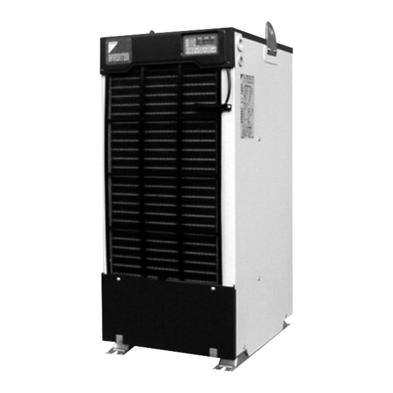
DAIKIN Oil Cooling Unit
("OILCON")
AKZ8 Series
Models
Menu
Built-in
Standard
breaker
model
model (-B)
Series
AKZ148
AKZ328
AKZ438
AKZ568
AKZ908
Thank you for purchasing DAIKIN Oil Cooling Unit ("OILCON").
This instruction manual includes instructions for using the Oil
Cooling Unit.
To ensure proper use of this product, be sure to read through this
instruction manual before using it.
After reading this manual, keep it handy for your future reference.
Proper use results in power saving
If the air filter is clogged, the cooling performance deteriorates,
causing excess power consumption.
Clean the air filter periodically to reduce power consumption.
Instruction Manual
Circulating type
Built-in heater
Built-in tank
model
model
Built-in breaker
model
CE model
Built-in
Different-
CE model
heater
voltage
(-C)
model (-H)
model (-E)
Installation
Handling
Different-voltage
model
(or Machine Temperature)
Built-in
tank model
(-T1, -T)
Devices (Installed by User)
Maintenance
• When the unit operation seems abnormal
although no alarm is activated
CONTENTS
1
4
5
6
7
12
14
15
16
18
19
20
21
22
23
24
25
27
30
33
33
34
35
36
37
38
Advertisement
Table of Contents

Related Manuals for Daikin AKZ438


Summarization of Contents
Safety Precautions
Risk Categories and General Instructions
Classifies hazardous conditions by severity (death, injury, property damage) and provides general safety advice.
Installation Safety Precautions
Safe Installation Practices
Covers qualified personnel, unit handling, grounding, wiring, transport, and fastening.
Electrical Safety & System Protection
Circuit breaker, flow switch, CE model requirements, and oil piping check.
Usage Safety Precautions
Operational Safety Measures
Power off duration, open covers, hot surfaces, specified conditions, explosive atmosphere.
Maintenance & Repair Safety
Do not disassemble, water exposure, cleaning precautions.
Environmental & Operational Safety
Ventilation for leaks, aperture safety, power supply, abnormal conditions.
Operational Checks & Maintenance
Special atmospheres, air intake, oil pollution, air filter, transport, operation lock.
Installation Procedure
Unit and Accessories Check
Verify Oil Cooling Unit and accessory package contents (manual, bushings).
Installation Place and Oil Piping
Requirements for installation location and oil piping specifications.
Pipe Selection Reference
Connection pipe diameters, pipe size/length charts, and resistance calculation.
Electric Wiring Guidelines
Wiring standards, circuit breaker, and internal wiring precautions.
Circuit Breaker Mounting
Requirements for mounting a circuit breaker, including earth leakage types.
Wiring Procedure Steps
Detailed steps for removing top plate, inserting cables, and connecting power.
Electrical Equipment Box Overview
Diagram of control board, terminals, and power supply connections.
Remote Control Input Connection
How to connect remote control switches and necessary parts.
External Output Contact Connection
Connecting signal cables for output status and parameter settings.
Output Logic and Timing Details
Parameters for output logic and timing charts for various signals.
Electric Wiring Diagram
Detailed wiring diagram for a typical model, showing components and connections.
Model Identification and Specifications
Model Identification System
Explains how to identify models using series and menu symbols.
Specifications (AKZ148/328/438)
Technical details for specific models including capacity, power, and dimensions.
Specifications (AKZ568/908)
Technical details for specific models including capacity, power, and dimensions.
Before Operation Checks
Operating Environment and Range
Checks for atmosphere, explosive gases, and adherence to operating range limits.
Installation, Piping, and Wiring
Verifying secure installation, oil piping, and electric wiring.
Applicable Oil and General Safety
Suitable oil types, electric wiring checks, and general safety.
Part Names and Functions
Standard Model Components (-B, -C)
Identifies key components and their functions for standard models.
Model Specific Components (-H, -E, -T1, -T)
Lists components specific to heater, different-voltage, and tank models.
Control Panel Parts Overview
Panel Indicators and Displays
Describes power lamp, operation mode indicator, and data displays.
Control Panel Keys
Explains the function of SELECT, DOWN, UP, ENTER, and TIMER lamps.
Operation Modes
Available Operation Modes
Lists seven modes and indicates normal operation modes.
Mode Changing and Initial Lock
How to change modes and cancel the initial operation lock.
Checking Initial Operating Conditions
Power On and Setup Verification
Steps for powering on, checking displays, and correcting reverse-phase connection.
Canceling Lock and Verifying Settings
How to cancel operation lock and check initial operating settings.
Operation Setting Modes
Constant Oil Temperature Control
Setting modes for controlling inlet or outlet oil temperature.
Tuning Oil Temperature Control
Setting modes for tuning oil temp to room or machine temperature.
Constant Capacity Cooling
Setting mode for cooling operation based on capacity command.
System Outline Drawing
Refrigerating Cycle Diagram and Description
Illustrates and explains the oil cooling system's components and cycle.
Holding Constant Oil Temperature
Inlet Oil Temperature Control
Setting mode 0 to maintain inlet oil temperature at a constant value.
Outlet Oil Temperature Control
Setting mode 1 to maintain outlet oil temperature at a constant value.
Setting Procedure
Step-by-step guide to select, change, and register temperature settings.
Tuning Oil Temperature
Tuning to Room Temperature
Setting modes 3 and 5 to match oil temp to room temperature.
Tuning to Machine Temperature
Setting modes 4 and 6 to match oil temp to machine temperature.
Setting Procedure
Step-by-step guide to set temperature difference and register it.
Cooling Oil at Constant Capacity (%)
Operation Mode 9 Functionality
Unit cools based on capacity command; oil temp control is disabled.
Setting Procedure
Step-by-step guide to set capacity designation and register it.
Monitor Items
Selectable Monitor Items
Lists items like machine, oil, room temps, capacity command, etc.
Operating Procedure
Steps to select monitor mode, view data, and return to normal.
Timer Operation
Timer Functionality and Range
Starts unit after set time (0-99 hrs); used for main machine warm-up.
Operating Procedure
Steps to select timer mode, set start time, and activate the timer.
Additional Setting Functions
Available Additional Functions
Auto-tuning, temp range warning, alarm output logic, communication.
Parameter List Overview
Table of parameters for additional functions, their settings, and remarks.
Parameter Setting Procedure
Entering Parameter Setting Mode
Steps to access parameter setting mode via control panel.
Selecting, Changing, and Registering Parameters
Guide to selecting parameter numbers, changing values, and registering.
Temperature Range Warning Function
Function Outline and Settings
Specifies temp range warning; options include output, compressor stop, FH alarm.
Parameter Groups and Application
Details on setting warning parameters and graphical application examples.
Parameter Settings Description (Group A)
Setting Warning Conditions and Operations
How to set parameters for temperature range warning conditions and operations.
Example Parameter Settings
Illustrates parameter settings for various temperature range warning scenarios.
Parameter Settings Description (Group B)
Setting Warning and Reset Temperatures
How to set warning temperatures and automatic reset temperatures.
Example Parameter Settings
Illustrates parameter settings for warning and automatic reset temperatures.
Auto-tuning Mode for Temp. Control
Function Outline and Benefits
Improves control by adjusting P/I gains for unstable or slow response.
Operation Steps and Parameters
Details operation steps and relevant parameters (n05-n09).
Auto-tuning Operation Flow
Starting and Executing Auto-tuning Steps
Flowchart showing steps from starting auto-tuning to completion.
Auto-tuning Notes and Considerations
Pre-tuning Conditions and Error Handling
Requirements before starting and how to handle errors during auto-tuning.
Parameter Settings and Refinements
Details on n04, n05 parameters and advice on multiple auto-tuning runs.
Alarm/Warning Output Logic
Signal Connection and Parameter n01
Connecting signals and setting parameter n01 for output logic.
Output Logic and Timing Details
Table showing output logic and timing for alarms and warnings.
Alarm Settings for Optional Protection Devices
Using OP Terminals [12] & [13]
Connecting devices to OP terminals and setting parameter n02.
Using OP 2 Terminal [CN2]
Connecting devices to CN2 and setting parameter n03.
Optional Parts: Machine Temperature Tuning
Optional Parts and Specifications
Lists thermistors for machine temp control, specs, and mounting.
Mounting Procedure and Cautions
Steps for connecting sensors and precautions for installation.
Optional Parts: Returned Oil Temperature Control
Optional Parts and Specifications
Lists thermistors for returned oil temp control, specs, and mounting.
Mounting Procedure
Steps for connecting thermistors and substituting connectors.
Optional Parts: Communication with Main Machine
Functionality and Optional Boards
Enables main machine control/monitoring via CS/CSP boards.
Mounting Procedures
Detailed steps for installing communication boards.
Maintenance and Inspection
Daily Maintenance Checks
Regular checks for oil, voltage, sounds, and unit stability.
Periodic Maintenance Tasks
Cleaning strainers, air filters, and condensers.
Exterior Cleaning and Storage
Guidelines for cleaning the exterior and preparing for storage.
Troubleshooting
Initial Checks and Contact Information
Points to check before contacting support and required info.
Abnormal Operation without Alarm
Table of issues, causes, and corrective actions for common problems.
Troubleshooting (continued)
Alarm List: Codes AA to E6
Details alarm codes, causes, and corrective actions for common alarms.
Troubleshooting (continued)
Alarm List: Codes E9 to 5E
Details alarm codes, causes, and corrective actions for remaining alarms.
Need help?
Do you have a question about the AKZ438 and is the answer not in the manual?
Questions and answers