
Related Manuals for HME Clear-Com BP410


Summary of Contents for HME Clear-Com BP410
- Page 1 User Guide Clear-Com HME DX410 EU Dual-Channel Wireless Intercom Part Number: 399G216 Rev A Date: 5/22/17...
- Page 2 No part of this document may be reproduced in any form by any means without prior written authorization of Clear-Com, an HME Company. Clear-Com Offices are located in California, USA; Cambridge, UK; Montreal, Canada; and Beijing, China.
- Page 3 FCC NOTICE This device complies with Part 15 of the FCC rules. Operation is subject to the following two conditions: (1) This device may not cause harmful interference, and (2) This device must accept any interference received, including interference that may cause undesired operation. NOTE: This equipment has been tested and found to comply with the limits for a Class A digital device, pursuant to Part 15 of the FCC rules.
- Page 4 Hereby, Clear-Com, LLC, an HM Electronics, Inc, company, declares that the DX410 is in compliance with the essential requirements and other relevant provisions of the RED (Radio Equipment Directive). In AFH mode, complies with European Telecommunications Standards Institute (ETSI) harmonized European standard EN 300 328. This product operates in the 2400 to 2483.5 MHz frequency range.
-
Page 5: Table Of Contents
TABLE OF CONTENTS System Overview ..............1 System Components . -
Page 6: System Overview
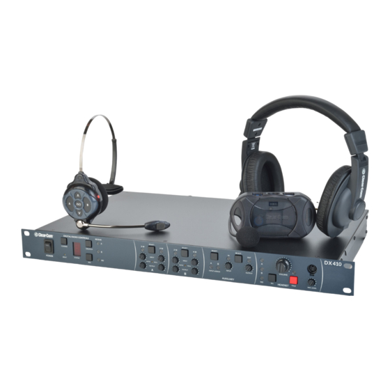
SYSTEM OVERVIEW ® The Clear-Com HME DX410 is a 2-channel Digital Wireless Intercom System that supports up to 15 ® COMMUNICATOR s per base station, either Belt Packs or All-In-One Headsets, or a combination of the two. Using the DX410 in the 2-channel mode, any three of the 15 Communicators can operate in full duplex mode. In the single-channel mode, any four Communicators can operate in full duplex mode. -
Page 7: Base Station Front Panel
Base Station Front Panel 18 20 22 21 26 28 Digital Radio Controls 20. (B) AUTO NULL button (recessed) 1. POWER switch 21. (B) 4-W input level adjust 2. CLR/BND button 22. (B) 4-W output level adjust 3. RESET button (recessed) 23. -
Page 8: Base Station Rear Panel
Base Station Rear Panel 1. ANT (R-TNC) 9. (B) 4-W RJ-45 Connector 2. PRIMARY/SECONDARY Select Switch 10. SINGLE/DUAL Channel Select Switch 3. (A) 4-W RJ-45 Connector 11. AUX IN Connector 4. (A) 2-W XLR-3M Connector 12. AUX OUT Connector 5. (A) 2-W XLR-3F Connector 13. -
Page 9: All-In-One Headset - Wh410
All-In-One Headset – WH410 1. Channel A (Intercom 1) button 6. Power/mode light 2. ISO (Isolate) button 7. Microphone 3. Volume-up button 8. Power button 4. Volume-down button 9. Battery 5. Channel B (Intercom 2) button 10. Battery-release latch... -
Page 10: System Setup
SYSTEM SETUP Displayed below is an example of a typical Clear-Com set up and configuration with the DX410. Battery Charging Before installing the system, connect the AC power supply to the battery charger and plug it into an electrical outlet. Charge all the batteries while the other equipment is being installed. Charging time is about 2.5 hours. -
Page 11: Charging The Batteries
Batteries in Charging ports Batteries in Storage ports Charging the Batteries Up to four batteries can be charged in the battery charger at one time. The battery status lights next to each charging port indicate the battery status. Up to four fully charged batteries can be stored in the battery Storage ports. Insert a battery in each of four Charging ports until it clicks in place. -
Page 12: Basic Base Station Setup
Basic Base Station Setup This section describes setup and equipment connections for an individual base station. 90° SINGLE/DUAL Channel select switch Base station rear panel AC power supply AC power cord Connect the two enclosed antennas to the antenna connectors on the rear panel of the base station, and turn the sleeves clockwise on the antenna connectors to tighten them securely in place. -
Page 13: Communicator
COMMUNICATOR Setup and Registration ® The first time you operate the DX410 system, you must register each Communicator (Belt Pack and/or All-In-One Headset) for use with a specific base station. The base station will then recognize all registered Communicators when their power is on and will differentiate between them and other electronic equipment operating on the same frequencies. - Page 14 All-In-One Headsets Changing Batteries When a battery weakens, a prompt in the headset will say “Change battery”. Remove the battery from the headset by pressing the blue battery-release latch. Battery-release latch Insert a fully charged battery in each Headset, with the battery’s (blue button) metal contacts inserted first.
- Page 15 ® Register COMMUNICATOR The Communicator must be within 6 feet (1.83 meters) of the base station to enable registration. Be certain all headsets to be registered are turned OFF, and the base station power is ON. Place the headset on your head. Press the REG button on the front panel of the base station.
- Page 16 ® COMMUNICATOR Settings If you want to set up a Communicator with any of the special settings shown below, press and hold the specified button combinations during or after power up. These settings will remain in memory when the Communicators are turned off and on again.
-
Page 17: Interfacing With 2-Wire Or 4-Wire Intercoms
Interfacing with 2-Wire or 4-Wire Intercoms Base station rear panel 2-Wire Intercom Interface The following 2-wire setup is for Channel 1 (A). If applicable, repeat for Channel 2 (B). If using a 2-wire intercom with the DX410, plug it into the base station 2-W connector at ( ) or ( depending on whether a male or female connection is required. -
Page 18: Interfacing With Auxiliary Audio Equipment
A and B Intercom Controls and Indicator Lights Base station front panel The A portion of this area of the panel is for Intercom Channel A, and the B portion is for Intercom Channel 2. Their operation is identical. The SELECT button ( ) is used to select 2-Wire ( ) or 4-Wire ( ) or both. -
Page 19: Iso Relay
The AUXILIARY SELECT button ( ) is used to select A or B or both as the destination for AUX IN audio. The A and/ or B INPUT ASSIGN lights ( ) come on green to indicate the selection as the destination for AUX IN audio. If neither is ®... -
Page 20: System Operation
SYSTEM OPERATION ® This chapter describes how to operate the Base Station and COMMUNICATOR (Belt Pack or All-In-One Headset). Base Station Operation ® COMMUNICATOR Audio Channel and Local Headset Registration Auto-Null Controls Connector & Controls Power Switch AUX IN Assign and AUX In/Out Controls System and Registration Controls and Indicator Lights The CLR/BND button, RESET button, STATUS indicator and REG button are used when registering... -
Page 21: Communicator ® Operation
COMMUNICATOR ® OPERATION Belt Pack control buttons have a snap action. They will activate when pressed firmly. Use your fingertips (not your fingernails) to press the Belt Pack buttons. All-In-One Headset buttons are touch sensitive. Power On/Off Power On – Press and release the Power button (PWR). A voice prompt in the ear piece will say “Battery Level”, and the red power lights near the corners of the A and B buttons will turn on. - Page 22 Adjusting Microphone Gain Some users talk louder/softer than others. To allow for this, microphone gain adjustment is available. To increase microphone gain – While holding down the B button, press the volume-up ▲ button as many times as necessary to reach the desired level. The microphone gain increase can be monitored through side tone, or preferably by someone else using a Communicator or at the base station.
-
Page 23: Eu Base Station Adaptive Frequency Hopping (Afh)
EU BASE STATION ADAPTIVE FREQUENCY HOPPING (AFH) Hereby, HM Electronics, Inc., declares that DX410 is in compliance with the essential requirements and other relevant provisions of R&TTE Directive 1999/5/EC” with “Radio Equipment Directive (RED). In AFH mode, DX410 complies with European Telecommunications Standards Institute (ETSI) harmonized European standard EN 300 328. - Page 24 Physical separation. If possible, equipment operating in the 2.4 GHz spectrum should be operating as far as physically possible from the HME base station. A Wi-Fi access point or router is a common piece of equipment that could interfere with the DX410 system, or vice versa. These two pieces of equipment in particular should not be located close together.
-
Page 25: Troubleshooting
TROUBLESHOOTING Problem THINGS TO CHECK The Red light on base station power switch does not Be sure the power cords are properly connected to base come on. station, power supply and electrical outlet. Be sure your base station power is on. Turn the Belt The Belt Pack power lights do not turn green and “out Pack and base station power on and off. -
Page 26: Technical Data
TECHNICAL DATA BS410 Base Station Specifications General Channels 2 audio channels Frequency Range 2400 – 2483.5 MHz Frequency Response 200 Hz to 7 kHz Power Requirements 100-240VAC, 50-60Hz or 12-14VDC Temperature Range 32-122°F (0-50°C) Size 19” x 1.72” x 17.13” (1-RU) (48.26 x 4.37 x 43.51 cm) Weight 9.0 lbs. -
Page 27: Bp410 Belt Pack Specifications
BP410 Belt Pack Specifications General Channels 2 audio channels Frequency Range 2400 – 2483.5 MHz Antenna Internal, horizontal/vertical diversity Frequency Response 200 Hz to 7 kHz Battery Requirements 3.6V lithium ion Battery Life Up to 20 hours Temperature Range 32-122°F (0-50°C) Weight 7.4 oz (.21 kg) with battery and pouch Headset Connector... -
Page 28: Wh410 All-In-One Headset Specifications
WH410 All-In-One Headset Specifications General Channels 2 audio channels Frequency Range 2400 – 2483.5 MHz Antenna Internal Frequency Response 200 Hz to 7 kHz Battery Requirements 3.6V lithium ion Battery Life Up to 20 hours Temperature Range 32-122°F (0-50°C) Weight 5.7 oz (.16 kg) with battery Microphone Electret... -
Page 29: Appendix A: Communicator ® Indicator Light Functions
APPENDIX A: COMMUNICATOR Indicator Light Functions ® BP410 Belt Pack Indicator Lights BP410 Condition A Indicator Light B Indicator Light A Idle Steady Green A TX Blinks Green B Idle Steady Green B TX Blinks Green ISO TX Blinks Green Blinks Green Low battery Appropriate channel light Blinks Red when in idle mode... -
Page 30: Appendix B: Multiple Base Station Daisy-Chaining
APPENDIX B: MULTIPLE BASE STATION DAISY-CHAINING Two or more DX410 base stations can be “daisy-chained” together with cables connected to the 2-W connectors on the ® ® rear panels of each base station (following Clear-Com / RTS standards), or two base stations (not more) can be “daisy- chained”... -
Page 31: Appendix C: Jumper Settings
APPENDIX C: JUMPER SETTINGS The base station has internal jumpers that are used to set ISO broadcast restrict, power detect by-pass, and 2-wire channel termination. Jumper # Function Default Split ‘ISO’ ISO No Broadcast Channel A, 2-wire termination Ch A 4w to 2w audio bridge Ch B 4w to 2w audio bridge JP10 Ch A 2w to 4w audio bridge... -
Page 32: Dx Series Led Aid
DX SERIES LED AID Powering on any DX base station will produce on the LED display the number “8” for approximately 3 seconds. Blank display indicates the base is ready for operation. You can register belt packs under this condition. Single horizontal bar indicates the base is in secondary mode and registering to a base has been initiated and successfully linked with a primary base. - Page 33 The lower case “c” will appear when the registry on the base station is cleared. To clear the registry power down the base. Hold down the CLR/BND or RESET REGISTRATION* button first and then power the base on when you see the “8” on the LED display release the CLR/BND or RESET REGISTRATION*. If done successfully you will see a small "c"...
-
Page 34: Appendix D: Audio Routing Diagram
APPENDIX D: AUDIO ROUTING DIAGRAM CH. B 2WT04W CH. B 4WT02W CH. A 2WT04W CH. A 4WT02W... -
Page 35: General Battery Safety Instructions For Battery Model Bat41, Bat50, Bat60
GENERAL BATTERY SAFETY INSTRUCTIONS FOR BATTERY MODEL BAT41, BAT50, BAT60... -
Page 36: French
DIRECTIVES DE SÉCURITÉ GÉNÉRALES POUR LES MODÈLES DE BATTERIE SUIVANTS : BAT41, BAT50, BAT60... -
Page 37: Spanish
INSTRUCCIONES GENERALES DE SEGURIDAD PARA BATERÍAS PARA CADA MODELO DE BATERÍA: BAT41, BAT50, BAT60... -
Page 38: Korean
BAT41, BAT50, BAT60...
Need help?
Do you have a question about the Clear-Com BP410 and is the answer not in the manual?
Questions and answers