Table of Contents
Advertisement
Micro830, Micro850, and Micro870
Programmable Controllers
Micro810 Controller Catalog Numbers 2080-LC10-12AWA, 2080-LC10-12QWB, 2080-LC10-12DWD, 2080-LC10-12QBB
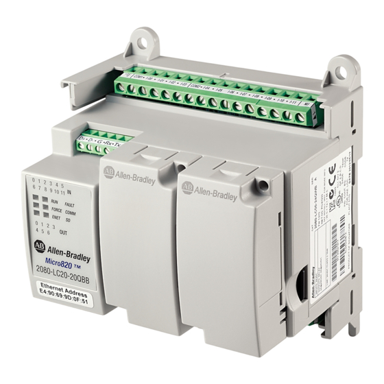
Micro820 Controller Catalog Numbers 2080-LC20-20AWB, 2080-LC20-20AWBR, 2080-LC20-20QWB, 2080-LC20-20QWBR,
2080-LC20-20QBB, 2080-LC20-20QBBR
Micro830 Controller Catalog Numbers 2080-LC30-10QWB, 2080-LC30-10QVB, 2080-LC30-16AWB, 2080-LC30-16QWB,
2080-LC30-16QVB, 2080-LC30-24QWB, 2080-LC30-24QVB, 2080-LC30-24QBB, 2080-LC30-48AWB, 2080-LC30-48QWB,
2080-LC30-48QVB, 2080-LC30-48QBB
Micro850 Controller Catalog Numbers 2080-LC50-24AWB, 2080-L50E-24AWB, 2080-LC50-24QWB, 2080-L50E-24QWB,
2080-LC50-24QVB, 2080-L50E-24QVB, 2080-LC50-24QBB, 2080-L50E-24QBB, 2080-LC50-48AWB, 2080-L50E-48AWB,
2080-LC50-48QWB, 2080-L50E-48QWB, 2080-LC50-48QWBK, 2080-L50E-48QWBK, 2080-LC50-48QVB, 2080-L50E-48QVB,
2080-LC50-48QBB, 2080-L50E-48QBB
Micro870 Controller Catalog Numbers 2080-LC70-24AWB, 2080-L70E-24AWB, 2080-LC70-24QWB, 2080-L70E-24QWB,
2080-LC70-24QWBK, 2080-L70E-24QWBK, 2080-L70E-24QWBN, 2080-LC70-24QBB, 2080-L70E-24QBB, 2080-LC70-24QBBK,
2080-L70E-24QBBK, 2080-L70E-24QBBN
User Manual
Original Instructions
Advertisement
Table of Contents
Troubleshooting

Related Manuals for Rockwell Automation Allen-Bradley Micro810


Summarization of Contents
Chapter 1 Hardware Overview
Hardware Features
Details the key hardware characteristics of Micro830, Micro850, and Micro870 controllers, including module capacity and power supply compatibility.
Micro830 Controllers
Provides an overview and status indicator details for Micro830 10/16-point and 24-point controllers.
Micro850 Controllers
Details the hardware features and status indicators for Micro850 24-point and 48-point controllers.
Micro870 Controllers
Outlines the hardware specifications and status indicators for Micro870 24-point controllers.
Programming Cables
Explains the use of standard USB A Male to B Male cables for programming Micro800 controllers.
Embedded Ethernet Support
Describes the 10/100 Base-T Ethernet port on Micro850/Micro870 controllers and its LED indicators.
Chapter 3 Install Your Controller
Controller Mounting Dimensions
Provides detailed mounting dimensions for Micro830, Micro850, and Micro870 controllers, excluding feet or DIN rail latches.
DIN Rail Mounting
Details the procedure for mounting the controller module onto a DIN rail using the integrated latch.
Panel Mounting
Explains the preferred method of mounting the controller using four M4 screws per module.
Chapter 4 Wire Your Controller
Wiring Requirements and Recommendation
Outlines essential wiring practices including spacing, power routing, signal separation, and conduit usage.
Use Surge Suppressors
Explains the requirement for surge suppression to protect controller output contacts from inductive load switching surges.
Grounding the Controller
Provides guidance on mounting the product to a well-grounded surface like a metal panel for proper grounding.
Controller I/O Wiring
Offers relevant information on minimizing electrical noise and includes wiring examples for I/O connections.
Minimize Electrical Noise
Discusses methods to reduce electrical noise effects on controller input signals, including enclosure and grounding.
Embedded Serial Port Wiring
Details the wiring for the embedded RS-232/RS-485 serial port, including cable examples.
Chapter 5 Communication Connections
Supported Communication Protocols
Lists the communication protocols supported by Micro830, Micro850, and Micro870 controllers, including serial and Ethernet options.
Modbus RTU
Describes the Modbus RTU master and slave protocols and their configuration for serial ports.
ASCII
Explains ASCII communication for connecting to devices like barcode readers and serial printers via RS-232/RS-485 ports.
Modbus TCP Client/Server
Details the Modbus TCP protocol over Ethernet, utilizing Modbus mapping features similar to Modbus RTU.
Configure Serial Port
Guides on configuring the serial port driver as CIP Serial, Modbus RTU, ASCII, or Shutdown within Connected Components Workbench.
Configure Ethernet Settings
Provides instructions for configuring Internet Protocol (IP) settings, including DHCP or static IP address configuration.
Chapter 6 Micro870 Controller Distributed Network Protocol
Channel Configuration for DNP3 Slave
Explains how to configure serial and Ethernet ports for DNP3 Slave communication.
DNP3 Slave Application Layer
Covers DNP3 Slave Application Layer Function Codes and Internal Indications.
DNP3 Objects and Controller Variables
Details the DNP3 Objects supported by the controller and the mapping to controller variables.
Diagnostics
Explains how to access communication diagnostics for serial and Ethernet ports in Connected Components Workbench.
Chapter 7 Program Execution in Micro800
Overview of Program Execution
Provides a brief overview of running and executing programs with a Micro800 controller.
Execution Rules
Illustrates the four main steps of program execution within a scan cycle: reading inputs, executing POUs, writing outputs, and housekeeping.
Controller Load and Performance Considerations
Discusses how controller activities like interrupts and communication can impact program scan cycle time.
Memory Allocation
Details the memory allocation for Micro800 controllers based on point count and type.
Chapter 8 Motion Control
PTO Motion Control
Explains the use of Pulse Train Outputs (PTO) for accurate pulse generation to control servo motors.
Use the Micro800 Motion Control Feature
Introduces new users to the elements of motion control, including pulse train outputs, axes, and function blocks.
Motion Control Function Blocks
Details the function blocks used to instruct an axis for specified position, distance, velocity, and state.
General Rules for the Motion Control Function Blocks
Provides general rules for working with motion control function blocks, including input parameters and error handling.
Limits
Explains how to edit limit parameters such as Hard Limits, Soft Limits, and PTO Pulse Limits for axis motion control.
Motion Stop
Describes the three types of stops available for an axis: Immediate Hardware Stop, Immediate Soft Stop, and Decelerating Soft Stop.
Chapter 9 Use the High-Speed Counter and Programmable Limit Switch
High-Speed Counter Overview
Introduces the High-Speed Counter (HSC) feature, its hardware components, and application instructions.
What is High-Speed Counter?
Defines High-Speed Counter (HSC) functionality, its specialized instructions, and parallel operation with the system processor.
HSC Inputs and Wiring Mapping
Details the dedicated inputs for HSCs across different controller models and wiring configurations.
High-Speed Counter (HSC) Function Block
Explains how to use the HSC function block to start/stop counting, refresh status, reload settings, and reset the accumulator.
HSC Interrupts
Provides information on configuring and using HSC interrupts for executing selected user logic at pre-configured events.
Chapter 10 Controller Security
Protected Mode
Restricts operations that can disrupt controller operation based on the controller's current operating mode.
Exclusive Access
Ensures only one software session has exclusive access to the Micro800 controller application configuration.
Password Protection
Restricts access to programming software connections by requiring a password for upload and download operations.
Work with a Locked Controller
Provides workflows for uploading, debugging, downloading, and transferring programs to password-protected controllers.
Configure Controller Password
Details the procedure for setting, changing, and clearing the controller password.
Chapter 11 Using microSD Cards
Overview
Describes microSD card support on Micro830, Micro850, and Micro870 controllers for project backup, data log, and recipe functions.
Project Backup and Restore
Explains how to perform project backup and restore operations using the microSD card and Connected Components Workbench.
Data Log
Details the data logging feature for capturing global and local variables with timestamps into the microSD card.
Recipe
Covers the Recipe feature for storing and loading data to/from recipe files using the RCP instruction.
Appendix A Modbus Mapping for Micro800
Modbus Mapping
Explains Modbus RTU and TCP support, endian configuration, and address space mapping for Micro800 controllers.
Example 1, PanelView 800 HMI (Master) to Micro800 (Slave)
Provides steps for configuring communication between a PanelView 800 HMI and a Micro800 controller using Modbus RTU.
Appendix B Quickstarts
Flash Upgrade Your Micro800 Firmware
Guides on how to flash update the firmware for a Micro800 controller using Connected Components Workbench software.
Configure Controller Password
Provides instructions for setting, changing, and clearing the controller password via Connected Components Workbench.
Use Run Mode Change
Explains how to make small logic changes to a running project and test them without disconnecting from the controller.
Appendix C User Interrupts
Information About Using Interrupts
Explains fundamental properties of User Interrupts, including what they are, when they can occur, and their priority.
User Interrupt Configuration
Details how to configure user interrupts and set them as AutoStart from the Interrupts window.
Using the Selectable Timed Interrupt (STI) Function
Describes how to use the Selectable Timed Interrupt (STI) to solve time-critical control requirements.
Using the Event Input Interrupt (EII) Function
Explains how the Event Input Interrupt (EII) allows scanning a specific POU when an input condition is detected from a field device.
Appendix D Troubleshooting
Status Indicators on the Controller
Provides diagrams of status indicators for Micro830, Micro850, and Micro870 controllers.
Error Codes
Lists possible error codes for controllers and recommended actions for recovery.
Fault Types
Categorizes faults into Recoverable (cleared by power cycle) and Non-recoverable (requires power cycle).
Controller Error Recovery Model
Provides a model to help diagnose software and hardware problems in the controller.
Appendix E PID Function Blocks
IPIDCONTROLLER Function Block
Details the arguments and function block diagram for the IPIDCONTROLLER, which supports auto-tune.
How to Autotune
Provides steps and recommendations for performing an autotune process on PID systems.
Troubleshooting an Autotune Process
Offers insights into autotune process sequences and actions to take if autotune fails.
PID Application Example
Illustrates a basic water level control system example for PID application.
Appendix F System Loading
Calculate Total Power for Your Micro830/Micro850/Micro870 Controller
Provides a formula and examples to calculate the total power requirements for Micro8xx controllers with plug-ins and I/O.
Appendix G Connect to Networks using DF1
DF1 Full-Duplex Protocol
Describes the DF1 Full-Duplex protocol for point-to-point connections and its support for data transparency and simultaneous transmission.
DF1 Half-Duplex Protocol
Explains the DF1 Half-Duplex protocol for multi-drop networks, supporting various modem types and controller roles.
Configure DF1 Half-Duplex Parameters
Details configuration parameters for DF1 Half-Duplex, including RTS Send Delay and RTS Off Delay.
Configure a Standard-Mode DF1 Half-Duplex Master Station
Guides on configuring the controller as a master station for querying slave stations using standard communication mode.
Configure a Slave Station
Provides steps to configure the controller as a slave station for DF1 Half-Duplex communication.
Need help?
Do you have a question about the Allen-Bradley Micro810 and is the answer not in the manual?
Questions and answers