Table of Contents
Advertisement
Quick Links
Advertisement
Table of Contents

Subscribe to Our Youtube Channel
Related Manuals for Rockwell Automation Allen-Bradley SMC Dialog Plus


Summary of Contents for Rockwell Automation Allen-Bradley SMC Dialog Plus
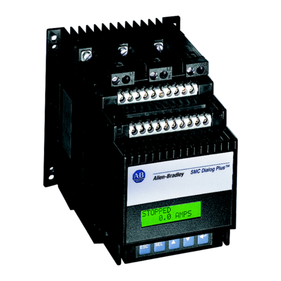
- Page 1 Quick Start SMC Dialog Plus™ Controller Bulletin 150...
-
Page 2: Important User Information
In no event will Rockwell Automation, Inc. be responsible or liable for indirect or consequential damages resulting from the use or application of this equipment. -
Page 3: Cautions And Warnings
440-646-5800, option 2, option 4 Telephone Support or use direct dial code 804 Cautions and Warnings The following cautions and warnings must be observed while installing and using the SMC Dialog Plus controller. Rockwell Automation Publication 150-QS002B-EN-P - October 2011... -
Page 4: General Precautions
(PFCC). The PFCC capacitors must only be located on the line side of the SMC. Installing PFCC capacitors on the load side wil result in SCR damage and failure. ATTENTION: After a short-circuit occurs, device functionality must be verified. Rockwell Automation Publication 150-QS002B-EN-P - October 2011... -
Page 5: Human Interface Module
Refer to the applicable standards for emergency stop requirements. Control Options Soft Stop ATTENTION: Soft Stop is not intended to be used as an emergency stop. Refer to the applicable standards for emergency stop requirements. Rockwell Automation Publication 150-QS002B-EN-P - October 2011... -
Page 6: Fast Acting Current-Limiting Fuses
This type of fuse has a limited thermal capacity that is less than that of the SCRs they are designed to protect. This makes them susceptible to thermal fatigue. Rockwell Automation Publication 150-QS002B-EN-P - October 2011... -
Page 7: Installation
The controller is convection cooled. It is important to mount the controller in a position that allows air to flow vertically through the power structure. Allow for a minimum of six inches (15 cm) of free space around all sides of the controller. Rockwell Automation Publication 150-QS002B-EN-P - October 2011... -
Page 8: Power Wiring
Heatsink Fan VA 97…360 A 500 A 650…1000 A Control Terminals Figure 1 - SMC Dialog Plus Controller Control Terminals Table 2 - Control Terminal Designation Terminal Number Description Control Power Input Control Power Common Rockwell Automation Publication 150-QS002B-EN-P - October 2011... - Page 9 Converter Module Fanning Strip Connection Auxiliary Contact #3 Auxiliary Contact #3 Ê Do not connect any additional loads to these terminals. These “parasitic” loads may cause problems with operation, which may result in false starting and stopping. Rockwell Automation Publication 150-QS002B-EN-P - October 2011...
- Page 10 Refer to Chapter 3 of the SMC Dialog Plus Controller User Manual (Publication 150-5.3) for optional 220/240V AC fan power connections and other sample wiring diagrams. Chapter 7 of Publication 150-5.3 also provides typical wiring diagrams for the control options (for example, Pump Control). Rockwell Automation Publication 150-QS002B-EN-P - October 2011...
-
Page 11: Keypad Description
After a parameter value has been Enter entered into memory, the top line of the display will automatically become active, allowing the user to scroll to the next parameter. Rockwell Automation Publication 150-QS002B-EN-P - October 2011... - Page 12 The SMC Dialog Plus controller does not support EEPROM, Link, Process, or Start-up modes Steps back one level. Control Status and Search are only available when using a Series B Bulletin 1201 human interface module. Password protected. English is currently the only available language. Rockwell Automation Publication 150-QS002B-EN-P - October 2011...
- Page 13 English is currently the only available language For further information on parameters, see Appendix B of the SMC Dialog Plus User Manual, Publication 150-5.3. For further information on parameter management, see the SMC Dialog Plus User Manual, Publication 150-5.3. Rockwell Automation Publication 150-QS002B-EN-P - October 2011...
-
Page 14: Factory Default Settings
Dialog Plus controller to the connected motor. A clamp-on ammeter, which provides a true rms measurement and has a published accuracy of ±1% (Fluke model 33 or equal), is required to perform this procedure. Rockwell Automation Publication 150-QS002B-EN-P - October 2011... - Page 15 ##.# AMPS SMC Dialog Plus controller is now calibrated. The currents should measure a minimum of 70% of the motor’s full load current rating in order to achieve the best results in accuracy. Rockwell Automation Publication 150-QS002B-EN-P - October 2011...
- Page 16 Bulletin 1201 human interface module or a variety of Bulletin 1203 communication modules. Figure 6 - SCANport Location SCANport ATTENTION: Only one peripheral device can be connected to the SCANport. The maximum output current is 100 mA. Rockwell Automation Publication 150-QS002B-EN-P - October 2011...
-
Page 17: Human Interface Modules
2. Select the Enable option of Control Logic. 3. Press Enter. Control Logic must be disabled or the Logic Mask set to 0 prior to IMPORTANT disconnecting a human interface module from the SMC Dialog Plus controller. Rockwell Automation Publication 150-QS002B-EN-P - October 2011... - Page 18 Quick Start Notes: Rockwell Automation Publication 150-QS002B-EN-P - October 2011...
-
Page 20: Rockwell Automation Support
Rockwell Automation representative. New Product Satisfaction Return Rockwell Automation tests all of its products to ensure that they are fully operational when shipped from the manufacturing facility. However, if your product is not functioning and needs to be returned, follow these procedures.
Need help?
Do you have a question about the Allen-Bradley SMC Dialog Plus and is the answer not in the manual?
Questions and answers