Table of Contents
Advertisement
Quick Links
Operator's/Parts Manual
CPH and CP1000
Coulter Command System
Manufacturing, Inc.
P.O. Box 5060
Salina, Kansas 67402-5060
●
!
Read the operator's manual entirely. When you see this symbol, the subsequent in-
structions and warnings are serious - follow without exception. Your life and the lives of
others depend on it!
12611
Cover illustration may show optional equipment not supplied with standard unit.
© Copyright 1999 Printed
2/30/2002
148-258M-B
Advertisement
Table of Contents

Related Manuals for GREAT PLAINS CP1000


Summarization of Contents
Important Safety Information
Safety Rules
Key safety precautions for operating machinery to prevent accidents and ensure safe operation.
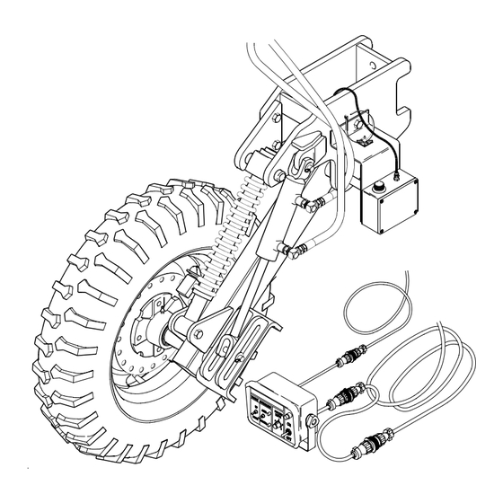
Introduction
Product Overview
Description of the Coulter Command system, its components, and function.
Using This Manual
Recommendations for reading and utilizing the manual for better understanding and future reference.
Definitions
Defines terms used in the manual, specifically right and left hand orientation.
Section 1 Assembly Instructions & Set-Up
Pre-Assembly Checklist
List of items to check before beginning the assembly of the Coulter Command system.
Coulter Command Assembly
Instructions for assembling the depth sensing wheel to the Coulter Command system.
Lift Switch Assembly
Detailed steps for assembling the lift switch to the transport cylinder.
Wiring Harness
Instructions for connecting the wiring harness for the Coulter Command system.
Tongue Cylinder
Instructions for assembling and installing the tongue cylinder.
Hydraulic Control Valve
Detailed steps for mounting and connecting the hydraulic control valve assembly.
Control Box
Instructions for mounting and connecting the control box in the tractor cab.
Coulter Command Assembly Adjustments
Procedures for adjusting the sensor box linkage for proper operation.
Section 2 Operating Instructions
Load Sensing Hydraulics
Information on bypass valves for load-sensing tractors and their setup.
Hydraulic Hook-Up & Function
How to connect and operate the system with closed-center hydraulic systems.
Open Center Hydraulic Systems
Guidance for tractors with open-center or fixed displacement hydraulic pumps.
Operation of Electronic Controls
How to operate the electronic controls for manual and automatic depth control.
Field Adjustments
Adjustments for the lift switch timing and position for optimal performance.
Speed Sensor
Information on the speed sensor and its function in compensating for ground speed.
Hydraulic Valve
Details on the hydraulic valve adjustments and tractor hydraulic system types.
Transport Cylinder Depth Channels
Information on an optional package for flotation in soft soil conditions.
Section 3 Troubleshooting
System Schematics
Schematics for hydraulic and electric systems to help locate problems.
Electrical Schematic
The electrical schematic diagram for the Coulter Command system.
Section 4 Maintenance and Lubrication
Maintenance
General information on the maintenance requirements of the Coulter Command system.
Lubrication
Details on lubrication symbols, intervals, and axle bearing lubrication.
Section 5 Parts
Coulter Depth Control Hydraulics
Illustrated parts breakdown for the hydraulic components of the Coulter Command system.
Coulter Command Electronics
Illustrated parts breakdown for the electronic components of the Coulter Command system.
Coulter Command Gauge Wheel Assembly
Illustrated parts breakdown for the gauge wheel assembly of the Coulter Command system.
Top Link Assembly
Illustrated parts breakdown for the top link assembly.
Coulter Command Switch Mount
Illustrated parts breakdown for the switch mount assembly.
Lift Circuit Manifold (810-262C)
Illustrated parts breakdown for the lift circuit manifold.
Coulter Depth Control Valve (810-214C)
Illustrated parts breakdown for the Coulter depth control valve.
O-Ring Identification Chart
Chart for identifying O-rings and back-up rings by size and kit number.
Appendix
Torque Values Chart for Common Bolt Sizes
Chart listing torque values for various common bolt sizes and grades.
Tire Inflation Chart
Chart providing recommended tire inflation pressures for different tire sizes.
Warranty
Details the warranty terms and conditions for the Great Plains seeding equipment.
Need help?
Do you have a question about the CP1000 and is the answer not in the manual?
Questions and answers