GREAT PLAINS CPH Operator And Parts Manual

GREAT PLAINS CPH Operator And Parts Manual

Coulter command system

Advertisement

Quick Links

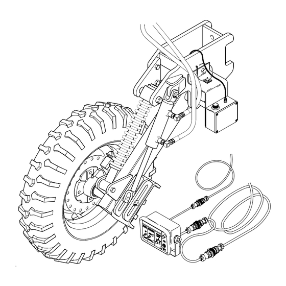
Operator's/Parts Manual
CPH and CP1000
Coulter Command System
Manufacturing, Inc.
P.O. Box 5060
Salina, Kansas 67402-5060
!
Read the operator's manual entirely. When you see this symbol, the subsequent in-
structions and warnings are serious - follow without exception. Your life and the lives of
others depend on it!
12611
Cover illustration may show optional equipment not supplied with standard unit.
© Copyright 1999 Printed
2/30/2002
148-258M-B

Advertisement

Table of Contents
loading
Need help?

Need help?

Do you have a question about the CPH and is the answer not in the manual?

Questions and answers

Subscribe to Our Youtube Channel

Summary of Contents for GREAT PLAINS CPH

  • Page 1 Operator’s/Parts Manual CPH and CP1000 Coulter Command System Manufacturing, Inc. P.O. Box 5060 Salina, Kansas 67402-5060 ● Read the operator’s manual entirely. When you see this symbol, the subsequent in- structions and warnings are serious - follow without exception. Your life and the lives of...
  • Page 2: Table Of Contents

    Warranty ....... 37 Field Adjustments ..... . . 12 CPH and CP1000 Coulter Command System 148-258M-B 9/21/05...
  • Page 3: Important Safety Information

    Coulter Command System has been designed with many built-in safety features. However, no one should operate this product before carefully reading this Opera- tor’s Manual. 9/21/05 CPH and CP1000 Coulter Command System 148-258M-B...
  • Page 4: Introduction

    Great Plains Great Plains parts. Therefore, should your Coulter Com- Manufacturing, Inc. assumes no responsibility for errors mand require replacement parts go to your Great Plains or omissions.
  • Page 5: Pre-Assembly Checklist

    If you are unsure where a fastener is used, use the parts section of this manual to identify it. Be sure the part gets used in the correct location. 12613 Figure 1 Coulter Command Assembly 9/21/05 CPH and CP1000 Coulter Command System 148-258M-B...
  • Page 6: Lift Switch Assembly

    1/2" jam nut. Once the be damaged. washer touches the bracket, lock the outer 1/2" Wiring Harness jam nut in place with the center 1/2" jam nut. e. Install spring (#25) and 1/2" nylock nut (#26). CPH and CP1000 Coulter Command System 148-258M-B 9/21/05...
  • Page 7 Great Plains Mfg., Inc. Section 1 Assembly Instructions & Set-Up 12612 Figure 2 Switch Assembly 9/21/05 CPH and CP1000 Coulter Command System 148-258M-B...
  • Page 8: Wiring Harness

    2. Plug the 4-Pin connector of the wiring harness to the will plug into the leads from the solenoids on the hy- draulic control valves after they are installed. 12617 Figure 3 Wiring Harness Assembly CPH and CP1000 Coulter Command System 148-258M-B 9/21/05...
  • Page 9: Tongue Cylinder

    8" x 8" hitch main tube. Connect one of the 36" long 1/4" hoses (#22) be- tween the port "C1" of the lower valve block and the 12672 Figure 4 Tongue Cylinder Disassembly 9/21/05 CPH and CP1000 Coulter Command System 148-258M-B...
  • Page 10 "A", The lead labeled "B" should be plugged into the solenoid marked "B," and the lead labeled "S1" should be plugged into the solenoid marked "S1." 13482 Figure 5 Hydraulic Control Valve Assembly CPH and CP1000 Coulter Command System 148-258M-B 9/21/05...
  • Page 11: Control Box

    With the depth sensing wheel in the max for proper assembly. down position, the marks should line up at a voltage of 5 volts DC + or - 1/4 volt. Aligning the marks is more 9/21/05 CPH and CP1000 Coulter Command System 148-258M-B...
  • Page 12: Section 2 Operating Instructions

    "P" and "T". Once the hydraulic valve is set valve, Great Plains part number 810-400C. Contact your for CLOSED CENTER operation, the Coulter Command Great Plains dealer to order the bypass valve.
  • Page 13: Open Center Hydraulic Systems

    Great Plains Mfg., Inc. Section 2 Operating Instructions The CPH transport hydraulic circuit contains the hoses other than the "priority circuit". Once the hydraulic valve from the ports marked "V1" and "V2". This circuit must is set for OPEN CENTER operation, the Coulter Com-...
  • Page 14: Operation Of Electronic Controls

    Center Pivot Hitch around in the field. coulter tool bar before switching the tongue hydraulics switch to the "auto" mode. Sudden automatic lowering of the coulter tool bar could cause serious personal injury or death. CPH and CP1000 Coulter Command System 148-258M-B 9/21/05...
  • Page 15: Speed Sensor

    (left side) on Center Pivot Hitches equipped should be in close proximity to the speed sensor plate. In with Coulter Command. general, it should never need adjustment. If the sensor 9/21/05 CPH and CP1000 Coulter Command System 148-258M-B...
  • Page 16: Section 3 Troubleshooting

    See "Lift Switch" under Section cylinder has been damaged. 2 "Operating Instructions" on page 12. Check cable connections on lift switch lead. CPH and CP1000 Coulter Command System 148-258M-B 9/21/05...
  • Page 17 For tractors with Pioneer quick couplers hydraulic flow through them. use Pioneer 8010-4P poppet style male couplers when operating in the OPEN CENTER mode. See Figure 8, page 9/21/05 CPH and CP1000 Coulter Command System 148-258M-B...
  • Page 18 OPEN CENTER MODE. See "Tractors hydraulic tongue circuit on an alternate with open center hydraulic systems remote if the tractor hydraulics allows or fixed displacement hydraulic live hydraulic power to other remotes. pumps," page 11. CPH and CP1000 Coulter Command System 148-258M-B 9/21/05...
  • Page 19: System Schematics

    Great Plains Mfg., Inc. Section 3 Troubleshooting System Schematics If problems occur in the hydraulic or electric systems, refer to the schematics below and on page 18 to help locate the problem. Hydraulic Schematic 16313 9/21/05 CPH and CP1000 Coulter Command System 148-258M-B...
  • Page 20: Electrical Schematic

    Great Plains Mfg., Inc. Section 3 Troubleshooting Electrical Schematic 16314 CPH and CP1000 Coulter Command System 148-258M-B 9/21/05...
  • Page 21: Section 4 Maintenance And Lubrication

    Lubrication is required every 50 hours of operation. Do not over lubricate. Seasonally Lubrication is required every 10 hours of operation. Lubrication is required 2 - 3 Years Axle Bearings Repack Type of Lubrication: Wheel Bearing Grease 12620 9/21/05 CPH and CP1000 Coulter Command System 148-258M-B...
  • Page 22: Section 5 Parts

    Great Plains Mfg., Inc. Section 5 Parts Section 5 Parts Coulter Depth Control Hydraulics 16317 CPH and CP1000 Coulter Command System 148-258M-B 9/21/05...
  • Page 23 Hydraulic Hose 1/4" R2 x 036 9/16" JIC Female 810-259C Cylinder 1.50" x 4.0" x 0.75" Weld 1" Pin 802-333C Bolt, Hex Head 5/16"-18 x 3 1/2" Long 810-262C Lift Circuit Manifold 9/21/05 Great Plains Mfg., Inc. CPH and CP1000 Coulter Command System 148-258M-B...
  • Page 24: Coulter Command Electronics

    Section 5 Parts Coulter Command Electronics 12623 CPH and CP1000 Coulter Command System 148-258M-B Great Plains Mfg., Inc. 9/21/05...
  • Page 25 Section 5 Parts Ref. Part No. Part Description 823-103C Control Box 823-110C Power Cord 823-108C Control Box Cable 823-104C Wire Harness 9/21/05 Great Plains Mfg., Inc. CPH and CP1000 Coulter Command System 148-258M-B...
  • Page 26: Coulter Command Gauge Wheel Assembly

    Section 5 Parts Coulter Command Gauge Wheel Assembly 12594 CPH and CP1000 Coulter Command System 148-258M-B Great Plains Mfg., Inc. 9/21/05...
  • Page 27 805-067C Pin, Cotter 1/8" x 3/4" 810-259C Cylinder 1.50" x 4.0" x 0.75" Weld 1" Pin 804-017C Washer, Flat 1/2" USS 805-128C Pin Clevis 1/2" x 2 3/4" 9/21/05 Great Plains Mfg., Inc. CPH and CP1000 Coulter Command System 148-258M-B...
  • Page 28: Top Link Assembly

    Section 5 Parts Top Link Assembly (Jan. 1, 2001) 12601 CPH and CP1000 Coulter Command System 148-258M-B Great Plains Mfg., Inc. 9/21/05...
  • Page 29 Nut, Lock 5/8"-11 148-084H Level Link Lock Plate 807-063C Spring, Level Link Lock 802-073C Bolt, Hex Head 1"-8 x 4" Long 804-027C Washer, Lock Spring 1" 803-031C Nut, Hex 1"-8 9/21/05 Great Plains Mfg., Inc. CPH and CP1000 Coulter Command System 148-258M-B...
  • Page 30: Coulter Command Switch Mount

    Section 5 Parts Coulter Command Switch Mount 12603 CPH and CP1000 Coulter Command System 148-258M-B Great Plains Mfg., Inc. 9/21/05...
  • Page 31 Bolt, Hex Head 5/16"-18 x 1 1/4" Long 804-010C Washer, Flat 5/16" USS 804-009C Washer, Lock Spring 5/16" 803-008C Nut, Hex 5/16"-18 803-084C Nut, Hex Nylock 5/16"-18 804-007C Washer, Flat 1/4" SAE 9/21/05 Great Plains Mfg., Inc. CPH and CP1000 Coulter Command System 148-258M-B...
  • Page 32: Lift Circuit Manifold (810-262C)

    Section 5 Parts Lift Circuit Manifold (810-262C) 13479 CPH and CP1000 Coulter Command System 148-258M-B Great Plains Mfg., Inc. 9/21/05...
  • Page 33 (Ref. Item #6) o-ring thin back-up "B" size "B" size "B" size thin back-up "B" size o-ring thin 13637 o-ring back-up "B" size 13635 thin 13636 back-up "B" size o-ring 9/21/05 Great Plains Mfg., Inc. CPH and CP1000 Coulter Command System 148-258M-B...
  • Page 34: Coulter Depth Control Valve (810-214C)

    Section 5 Parts Coulter Depth Control Valve (810-214C) 12292 CPH and CP1000 Coulter Command System 148-258M-B Great Plains Mfg., Inc. 9/21/05...
  • Page 35 (Ref. Item #6) "B" size "C" size thick back-up "E" size o-ring "E" size back-up "B" size o-ring thin "B" size back-up 12591 o-ring 12587 12590 "B" size o-ring 9/21/05 Great Plains Mfg., Inc. CPH and CP1000 Coulter Command System 148-258M-B...
  • Page 36: O-Ring Identification Chart

    OD 1.068 5/8"-18 Check Valves ID .862 OD .754 ID .614 OD .694 ID .530 OD 1.002 ID .798 OD .504 ID .364 Scale: 1=1 OD 1.193 ID .987 CPH and CP1000 Coulter Command System 148-258M-B Great Plains Mfg., Inc. 9/21/05...
  • Page 37 1 Each Of O-Rings Sizes A, B, C, And D 810-272C For 5/8"-18 Check Valves Includes: 1 Each of The Thick Back-Up Rings, Sizes B. 1 Each Of O-Rings Sizes A, And B. 9/21/05 Great Plains Mfg., Inc. CPH and CP1000 Coulter Command System 148-258M-B...
  • Page 38: Appendix

    12.5L x 15" 10-Ply Rib Implement 9.5L x 15" 8-Ply Rib Implement 16.5L x 16.1" 10-Ply Rib Implement 9.5L x 15" 12-Ply Rib Implement 41 x 15" x 18 - 22-Ply Rib Implement CPH and CP1000 Coulter Command System 148-258M-B 9/21/05...
  • Page 39: Warranty

    90 days for commercial or rental purposes. This War- ranty is limited to the replacement of any defective part by Great Plains Manufacturing, Incorporated and the installation by the dealer of any such replacement part.
  • Page 40 Great Plains Manufacturing, Inc. Corporate Offices: P.O. Box 218 Assaria, Kansas 67416 USA...

This manual is also suitable for:

Cp1000148-260a148-272a

Table of Contents