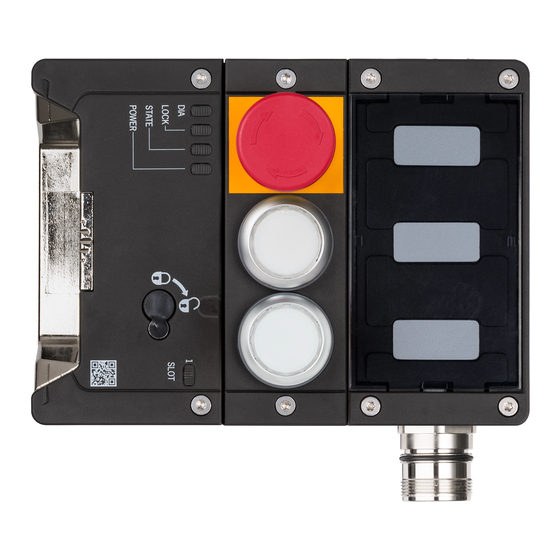
Summarization of Contents
1. About this document
1.1. Scope
Defines the scope and applicability of the operating instructions for MGB2 safety systems.
1.2. Target group
Identifies the intended audience for the operating instructions.
1.3. Key to symbols
Explains the meaning of various symbols used throughout the manual.
2. Correct use
2.1. Main differences, MGB2-BP and MGB2-BR
Highlights the key distinctions between the MGB2-BP and MGB2-BR system families.
6. Function
6.1. Locking module MGB2-L1/L2
Describes the functionality and operation of the MGB2-L1/L2 locking module.
6.2. Guard locking for version MGB2-L1
Explains the guard locking mechanism for the MGB2-L1 version.
6.3. Guard locking for version MGB2-L2
Explains the guard locking mechanism for the MGB2-L2 version.
7. System overview
7.1. Locking module MGB2-L.-...
Overview of the components and features of the MGB2-L locking module.
7.2. Handle module MGB2-H-...
Overview of the components and features of the MGB2-H handle module.
7.3. Escape release MGB-E-... (optional)
Description of the optional MGB-E escape release component.
7.4. Dimension drawing
Provides detailed dimensional drawings of the MGB2 system components.
7.4.1. Drilling pattern, overall system
Details the drilling pattern required for the overall system installation.
8. Manual release
8.1. Auxiliary release and auxiliary key release (can be retrofitted)
Explains how to use auxiliary and key releases for manual guard unlocking.
8.2. Emergency release (can be retrofitted)
Describes the operation of the emergency release feature.
8.3. Lockout mechanism
Details the lockout mechanism for securing the guard, including padlock use.
8.4. Escape release (optional)
Explains the functionality of the optional escape release.
8.4.1. Preparing escape release
Provides instructions on preparing and installing the escape release.
9. Mounting
9.1. Replacing modules
Step-by-step guide for replacing modules in the MGB2 device.
9.2. Mounting submodules
Instructions and precautions for mounting submodules.
9.3. Replacing submodules
Procedures for removing and replacing submodules.
9.3.2. Fitting and removing lenses and labels for controls and indicators
Guide to fitting and removing lenses and labels on controls and indicators.
9.4. Changing direction of connection
Instructions on how to change the direction of cable connections.
10. Changing the door hinge position
10.1. Changing the interlocking/locking module to a different door hinge position
Adjusting the module for doors with different hinge positions.
10.2. Changing actuating direction of the handle module
Modifying the actuating direction of the handle module.
13. Electrical connection
13.1. Using submodules
Information and compatibility notes for using submodules.
13.2. Notes about ULUS
Specific requirements and notes regarding UL/cULus approvals.
13.3. Safety in case of faults
Safety considerations and fault detection for electrical connections.
13.4. Fuse protection for power supply
Guidelines for implementing fuse protection for the power supply.
13.5. Requirements for connecting cables
Specifies the technical requirements for connecting cables.
13.6. Notes on cable laying
Recommendations and guidelines for proper cable laying.
13.7. Changing device configuration (using DIP switches)
Instructions for configuring the device settings via DIP switches.
13.7.1. Changing system family (BR/BP switching)
Procedure for switching between BR and BP system families using DIP switches.
13.7.2. Deactivating guard lock monitoring
Steps for deactivating the guard lock monitoring function.
13.7.3. Activating release monitoring
Steps for activating the release monitoring function.
13.8. Notes on operation with control systems
Important notes for connecting and operating with control systems.
13.9. Connection of guard locking control
Diagrams and information for connecting guard locking control circuits.
13.9.1. Guard locking control for devices with IMM connection
Connection example for guard locking control with IMM.
13.9.2. Guard locking control for devices without IMM connection
Connection example for guard locking control without IMM.
13.10. Terminal assignment and contact description
Detailed terminal assignments and description of contact functions.
13.11. Terminal assignment, submodule with plug connector M23 (X7)
Terminal assignment for submodules with M23 connectors.
13.12. Operation as separate device
Instructions for operating the MGB2 as a standalone device.
13.13. Information on operation in a BR switch chain
Guidance for integrating and operating the device in a BR switch chain.
14. Setup
14.1. Teach-in operation (only for MGB2 unicode)
Procedure for assigning the handle module to the locking module via teach-in.
14.2. Mechanical function test
Steps for performing a mechanical function test of the system.
14.3. Electrical function test
Steps for performing an electrical function test of the system.
15. System states
15.1. Key to symbols
Explains the meaning of symbols used to indicate system states.
15.2. System status table MGB2-BR
Details the various system states for the MGB2-BR configuration.
15.3. System status table MGB2-BP
Details the various system states for the MGB2-BP configuration.
15.4. System status table (Slot LED)
Explains the status indications provided by the Slot LED.
16. Technical data
16.1. Radio frequency approvals
Information regarding FCC and IC compliance and radio frequency approvals.
16.2. Typical system times
Provides typical system reaction and operation times.
17. Troubleshooting and assistance
17.1. Resetting errors
Step-by-step guide for resetting errors on the device.
17.2. Troubleshooting help on the Internet
Resources for online troubleshooting support and assistance.
17.3. Mounting help on the Internet
Online resources and animations for mounting assistance.
17.4. Application examples
Examples demonstrating device applications and integration.


Need help?
Do you have a question about the MGB2-L2 BR Series and is the answer not in the manual?
Questions and answers