
Related Manuals for EUCHNER MGB-L B-PN (PROFINET) Series


Summary of Contents for EUCHNER MGB-L B-PN (PROFINET) Series
- Page 1 Operating Instructions Safety Systems MGB-L..B-PN.-… (PROFINET) With Data Structure Type A...
-
Page 2: Table Of Contents
Operating Instructions Safety Systems MGB-L..B-PN.-… (PROFINET) and With Data Structure Type A Contents About this document ..................... 4 1.1. Scope ............................4 1.1.1. Notes on other product versions ..................4 1.2. Target group ..........................4 1.3. Key to symbols ..........................4 1.4. Supplementary documents ......................4 Correct use ...................... - Page 3 Operating Instructions Safety Systems MGB-L..B-PN.-… (PROFINET) and With Data Structure Type A Protection against environmental effects ............. 23 Controls and indicators ..................24 Electrical connection ..................25 13.1. Notes about .........................25 13.2. Connections on the bus module .....................26 13.2.1. Terminal assignment for version with push-pull plugs ............26 13.2.2.
-
Page 4: About This Document
Always read all documents to gain a complete overview of safe installation, setup and use of the device. The documents can be downloaded from www.euchner.com. For this purpose, enter the doc. no. or the order number for the device in the search box. -
Page 5: Correct Use
The safety system MGB can be combined only with the intended modules in the MGB system family. On the modification of system components, Euchner provides no warranty for function. The customer is responsible for the safe overall function, especially for the safe integration into the PROFIsafe environment. - Page 6 Operating Instructions Safety Systems MGB-L..B-PN.-… (PROFINET) and With Data Structure Type A Important! Ì Correct use requires observing the permissible operating parameters (see chapter 18. Technical data on page 34). Ì If a data sheet is included with the product, the information on the data sheet applies in case of discrepancies with the operating instructions.
-
Page 7: Description Of The Safety Function
Operating Instructions Safety Systems MGB-L..B-PN.-… (PROFINET) and With Data Structure Type A 3. Description of the safety function Devices from this series feature the following safety functions: The following applies in case of active guard lock monitoring (ÜK, bit SI 10): Monitoring of guard locking and the position of the guard (interlocking device with guard locking according to EN ISO 14119) Ì... - Page 8 Operating Instructions Safety Systems MGB-L..B-PN.-… (PROFINET) and With Data Structure Type A The following applies to devices with emergency stop: Emergency stop (emergency stop device according to EN ISO 13850) Ì Safety function: evaluation of emergency stop Ì Safety characteristics: B value for the emergency stop and PFH for the evaluation electronics (see chapter 18.
-
Page 9: Exclusion Of Liability And Warranty
Prior to use, read the operating instructions and keep these in a safe place. Ensure the operating instructions are always available during mounting, setup and servicing. For this reason you should archive a printed copy of the operating instructions. You can download the operating instructions from www.euchner.com. 2114575-07-03/24 (translation of the original operating instructions) -
Page 10: Function
Operating Instructions Safety Systems MGB-L..B-PN.-… (PROFINET) and With Data Structure Type A 6. Function 6.1. Interlocking module MGB-L0.B-PN. Together with a handle module, the interlocking module makes it possible to interlock movable guards. The combination also serves as a mechanical door stop at the same time. The following switch-on condition applies to safety bit SI 9 (SK): Ì... -
Page 11: Guard Locking For Version Mgb-L1
Operating Instructions Safety Systems MGB-L..B-PN.-… (PROFINET) and With Data Structure Type A 6.3. Guard locking for version MGB-L1 (guard locking actuated by spring force and released by power-ON) Activating guard locking: close guard, no voltage at the solenoid (safety bit SO 1 = 0). Releasing guard locking: apply voltage to the solenoid (safety bit SO 1 = 1). -
Page 12: Control Of Guard Locking
Operating Instructions Safety Systems MGB-L..B-PN.-… (PROFINET) and With Data Structure Type A 6.5. Control of guard locking From MGB version V2.36.4, the factory setting ensures that control is possible only from the safe control area. By changing the parameters in the configuration tool of your control system, it can be set whether bit O 16 (in the safe data block for the MGB locking module) is evaluated as well. -
Page 13: Case B
Operating Instructions Safety Systems MGB-L..B-PN.-… (PROFINET) and With Data Structure Type A 6.5.2. Case B You have an MGB with a version number of V3.30.0 and a GSD file with a version number of ..._110026-20110725 or older. The guard locking solenoid is controlled if for MGB-L1... -
Page 14: Case C
Operating Instructions Safety Systems MGB-L..B-PN.-… (PROFINET) and With Data Structure Type A 6.5.3. Case C You have an MGB with a version number of V3.30.0 and a GSD file with a version number from ..._110026-20110815. The guard locking solenoid is controlled if: Ì... -
Page 15: System Overview
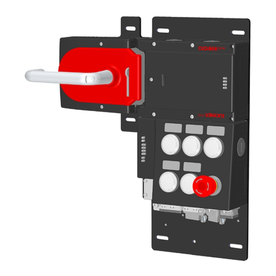
Operating Instructions Safety Systems MGB-L..B-PN.-… (PROFINET) and With Data Structure Type A 7. System overview Mounting plate Escape release (optional) (MGB-E...) Locking/release module (MGB-L...) Handle module (MGB-H...) Bus module (Profinet) (MGB-B...) Fig. 1: Components at a glance NOTICE MGB-PN systems are completely factory configured. The configuration must not be changed subse- quently. -
Page 16: Locking/Release Module Mgb-L
Operating Instructions Safety Systems MGB-L..B-PN.-… (PROFINET) and With Data Structure Type A 7.2. Locking/release module MGB-L.- Key: • LED indicator • Cover for auxiliary release • Locking arm (only version with guard locking) • Auxiliary marking for max. permissible mounting distance Notice: Depending on version, additional controls and indicators may be integrated into the cover. -
Page 17: Manual Release
Operating Instructions Safety Systems MGB-L..B-PN.-… (PROFINET) and With Data Structure Type A 8. Manual release Some situations require the guard locking to be released manually (e.g. malfunctions or an emergency). A function test should be performed after release. More information on this topic can be found in the standard EN ISO 14119:2013, section 5.7.5.1. The device can feature the following release functions: 8.1. -
Page 18: Lockout Mechanism
Operating Instructions Safety Systems MGB-L..B-PN.-… (PROFINET) and With Data Structure Type A 8.2. Lockout mechanism If the lockout mechanism is pivoted out/extended, the bolt tongue cannot be extended. The lockout mechanism can be secured with padlocks (see Fig. 7). This is intended to prevent people from being locked in unintentionally. The lockout mechanism does not fulfill any safety function. -
Page 19: Preparing Escape Release
Operating Instructions Safety Systems MGB-L..B-PN.-… (PROFINET) and With Data Structure Type A 8.3.1. Preparing escape release Profile width Length required for actuation Which EUCHNER parts are required? Necessary work steps axis Without With mounting mounting plates (4 mm plates each) D+17... -
Page 20: Mounting
Surface mounting Tip! Ì You will find an animation on the mounting process at www.mgb.euchner.com. Ì The color and labeling of pushbuttons and indicators can be modified. For mounting steps, see Fig. 9 and Fig. 10 to Fig. 15. -
Page 21: Mounting Lens
Operating Instructions Safety Systems MGB-L..B-PN.-… (PROFINET) and With Data Structure Type A Fig. 9: Installation example for door hinged on the right (general view) 9.1. Mounting lens Mounting 90° Click! Removal Lens 2114575-07-03/24 (translation of the original operating instructions) -
Page 22: Changing Actuating Direction
Operating Instructions Safety Systems MGB-L..B-PN.-… (PROFINET) and With Data Structure Type A 10. Changing actuating direction (here: from right to left) Important! It is possible to make this change only when the bolt tongue is not extended and an escape release is not yet mounted. -
Page 23: Protection Against Environmental Effects
Operating Instructions Safety Systems MGB-L..B-PN.-… (PROFINET) and With Data Structure Type A 3 mm CLOSED OPEN • Remove cover and undo hexagon socket screw. •• Move door handle 90° clockwise and fasten again. •• Tighten hexagon socket screw to 3 Nm. ••... -
Page 24: Controls And Indicators
Operating Instructions Safety Systems MGB-L..B-PN.-… (PROFINET) and With Data Structure Type A 12. Controls and indicators LEDs on the bus module Color Description 1 2 3 4 Binary coding of the DIP Link 1 and green Bus connector in- switches for PROFIsafe Link 2 serted: statically on address (factory setting:... -
Page 25: Electrical Connection
Important! Ì The supply for further devices on the bus may be forwarded via the Euchner MGB system. The entire supply current through the MGB must not be higher than specified in chapter 18. Technical data on page 34. -
Page 26: Connections On The Bus Module
Operating Instructions Safety Systems MGB-L..B-PN.-… (PROFINET) and With Data Structure Type A 13.2. Connections on the bus module The bus module includes the PROFINET connections (X3 and X4) and the power supply connections (X1 and X2). Depending on version, connection is made via push-pull plugs according to EN IEC 61076-3-117, variant 14, or 7/8" plugs according to ANSI/B93.55M-1981 and M12 plugs (d-coded) according to EN IEC 61076-3-101. -
Page 27: Setup
You will require the corresponding GSD file in GSDML format in order to integrate the MGB system: Ì GSDML-Vx.x-Euchner-MGB-PN_D_110026-YYYYMMDD.xml You will find the GSD file in the Download area at www.euchner.com. Prior to setup, the GSD file must be imported into the configuration software for the control system (see control system manual). -
Page 28: Teach-In Operation (Only For Mgb Unicode)
Operating Instructions Safety Systems MGB-L..B-PN.-… (PROFINET) and With Data Structure Type A 14.4. Teach-in operation (only for MGB unicode) The handle module must be assigned to the locking module using a teach-in function before the system comprising locking module and handle module forms a functional unit. The system is in a safe state (bits SI 3, SI 4, SI 5, SI 9 and SI 10 are not set) during a teach-in operation. -
Page 29: Profinet Data Bytes (Data Blocks For Non-Safe Functions)
Operating Instructions Safety Systems MGB-L..B-PN.-… (PROFINET) and With Data Structure Type A 14.7. PROFINET data bytes (data blocks for non-safe functions) NOTICE Ì See the associated data sheet for details on the bit assignment. Ì For details, see chapter 15. MGB system diagnostic messages on page 31. Profinet RT modules 3 bytes IO: Assignment in input area of the bus master: Assignment in output area of the bus master:... -
Page 30: Profisafe Data Bytes (Data Block For Safe Functions)
Operating Instructions Safety Systems MGB-L..B-PN.-… (PROFINET) and With Data Structure Type A 14.8. PROFIsafe data bytes (data block for safe functions) Safe PROFIsafe data are transmitted in addition to the non-safe PROFINET data. These data include all information about the door position and guard locking, emergency stop and enabling switch, for example. -
Page 31: Mgb System Diagnostic Messages
Operating Instructions Safety Systems MGB-L..B-PN.-… (PROFINET) and With Data Structure Type A 15. MGB system diagnostic messages All diagnostic messages are listed below. The scope of the possible messages can differ depending on MGB system version. PROFIsafe messages Test-pulse error (short-circuit monitoring detected an error) Display via BF LED (see Fig. -
Page 32: Profinet Alarms
Operating Instructions Safety Systems MGB-L..B-PN.-… (PROFINET) and With Data Structure Type A General messages of the overall system General messages of the overall system Description Measures/rectifying errors Description Measures/rectifying errors 274(2) Internal device error Contact our support organization. 277(1) MGB starting error 274(3) Signal sequence erroneous (e.g. -
Page 33: System Status Table
Operating Instructions Safety Systems MGB-L..B-PN.-… (PROFINET) and With Data Structure Type A 17. System status table LEDs on interlocking/locking module DIA (rd) Lock (ye), only MGB-L1/-L2 STATE (gn) POWER (gn) Device diagnostics input bit I 24 Device diagnostics input bit I 18 Device diagnostics input bit I 17 ÜK input bit SI 10... -
Page 34: Technical Data
Operating Instructions Safety Systems MGB-L..B-PN.-… (PROFINET) and With Data Structure Type A 18. Technical data NOTICE If a data sheet is included with the product, the information on the data sheet applies. Parameter Value Housing material Fiber glass reinforced plastic Die-cast zinc, nickel-plated, stainless steel, powder-coated sheet steel... -
Page 35: Dimension Drawings
Operating Instructions Safety Systems MGB-L..B-PN.-… (PROFINET) and With Data Structure Type A 18.1. Dimension drawings Locking set Dimensions with automatically extending lockout mechanism (optional) Padlock min. 6 Lockout mech- anism max. 10 37,5 Detail A closed open Link Data Link Data Figure shows fastening with mounting plates... - Page 36 Operating Instructions Safety Systems MGB-L..B-PN.-… (PROFINET) and With Data Structure Type A Locking set Dimensions with automatically extending lockout mechanism (optional) Padlock min. 6 Lockout mech- anism max. 10 37,5 Detail A closed open Link Data Link Data Link Data Link Data X1 DC24V...
- Page 37 Operating Instructions Safety Systems MGB-L..B-PN.-… (PROFINET) and With Data Structure Type A Control module MGB-B-...-PN on mounting plate (example based on MGB-B-A1W2A2-PN-123759) S91.2 S91.1 S91.3 Link Data Link Data X1 DC24V X2 DC24V X3 PN2 X4 PN1 2114575-07-03/24 (translation of the original operating instructions)
- Page 38 Operating Instructions Safety Systems MGB-L..B-PN.-… (PROFINET) and With Data Structure Type A Control module MGB-CB-...-PN on mounting plate (example based on MGB-CB-PN-114744) Link Data Link Data X1 DC24V X2 DC24V X3 PN2 X4 PN1 (translation of the original operating instructions) 2114575-07-03/24...
-
Page 39: Troubleshooting And Assistance
¨ 19.3. Troubleshooting help on the Internet You will find a help file on troubleshooting under “Support” in the service area at www.euchner.com. 19.4. Mounting help on the Internet You will find an animation on the mounting process at www.euchner.com. -
Page 40: Service
22. Declaration of conformity The product complies with the requirements according to Machinery Directive 2006/42/EC. The EU declaration of conformity can be found at www.euchner.com. Enter the order number of your device in the search box. The document is available under Downloads. - Page 41 Operating Instructions Safety Systems MGB-L..B-PN.-… (PROFINET) and With Data Structure Type A 2114575-07-03/24 (translation of the original operating instructions)
- Page 42 Operating Instructions Safety Systems MGB-L..B-PN.-… (PROFINET) and With Data Structure Type A (translation of the original operating instructions) Copyright: © Euchner GmbH + Co. KG, 03/2024 Subject to technical modifications; no responsibility is accept- ed for the accuracy of this information.
Need help?
Do you have a question about the MGB-L B-PN (PROFINET) Series and is the answer not in the manual?
Questions and answers