
Related Manuals for EUCHNER MGB2-I-BP Series


Summary of Contents for EUCHNER MGB2-I-BP Series
- Page 1 Operating Instructions Safety Systems MGB2-I-BP.-… / MGB2-I-BR.-… From V1.0.0...
-
Page 2: Table Of Contents
Operating Instructions Safety Systems MGB2-I-BP.-… / MGB2-I-BR.-… Contents About this document ..................... 4 1.1. Scope ............................4 1.1.1. Notes on older product versions ..................4 1.2. Target group ..........................4 1.3. Key to symbols ..........................4 1.4. Supplementary documents ......................5 Correct use ......................6 2.1. - Page 3 Operating Instructions Safety Systems MGB2-I-BP.-… / MGB2-I-BR.-… 12.7. Changing device configuration (using DIP switches) .................28 12.7.1. Changing system family (BR/BP switching) ..............28 12.8. Notes on operation with control systems ..................29 12.9. Terminal assignment and contact description ..................30 12.10. Terminal assignment, submodule with plug connector M23 (X7) ............31 12.11.
-
Page 4: About This Document
This section applies to operation as MGB2-BP This section applies to operation as MGB2-BR In this section, attention must be paid to the DIP switch settings Printed document Document is available for download at www.euchner.com Safety precautions Danger of death or severe injuries DANGER... -
Page 5: Supplementary Documents
Important! Always read all documents to gain a complete overview of safe installation, setup and use of the device. The documents can be downloaded from www.euchner.com. For this purpose enter the doc. no. in the search box. 2530674-02-03/21 (translation of the original operating instructions) -
Page 6: Correct Use
The safety system MGB2 may be combined only with the intended modules in the MGB2 system family. On the modification of system components, EUCHNER provides no warranty for function. Interlocking modules with the configuration MGB2-BR can be integrated into a BR switch chain. -
Page 7: Main Differences, Mgb2-Bp And Mgb2-Br
Operating Instructions Safety Systems MGB2-I-BP.-… / MGB2-I-BR.-… 2.1. Main differences, MGB2-BP and MGB2-BR System family Symbol Optimized for operation in safe control systems. MGB2-BP If series connection is not necessary, the number of terminals required can be reduced using this system family. Linking of several guards on one shutdown path. -
Page 8: General Safety Precautions
For this reason you should archive a printed copy of the operating instructions. You can download the operating instructions from www.euchner.com. 6. Function Together with a handle module, the interlocking module makes it possible to interlock movable guards. The combination also serves as a mechanical door stop at the same time. -
Page 9: System Overview
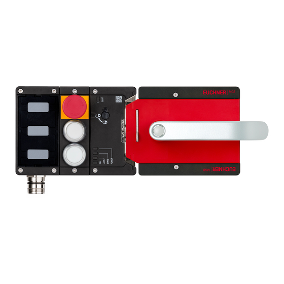
Operating Instructions Safety Systems MGB2-I-BP.-… / MGB2-I-BR.-… 7. System overview Key: 1 Interlocking module (MGB2-I…) 2 Escape release, optional (MGB-E-…) 3 Handle module (MGB2-H…) Fig. 1: Overall system 7.1. Interlocking module MGB2-I… Key: 1 Depending on version: cable entry M20x1.5 or plug connec- tor X7 2 Module function LED indicators 3 LED indicator for submodule in... -
Page 10: Escape Release Mgb-E
Operating Instructions Safety Systems MGB2-I-BP.-… / MGB2-I-BR.-… 7.3. Escape release MGB-E-… (optional) Key: 1 Door handle 2 Housing 3 Actuation axis 8 x 8 mm (different lengths available) 4 Protective sleeve Notice: Depending on version, a mounting plate can be included. See enclosed data sheet. -
Page 11: Dimension Drawing
Operating Instructions Safety Systems MGB2-I-BP.-… / MGB2-I-BR.-… 2530674-02-03/21 (translation of the original operating instructions) -
Page 12: Drilling Pattern, Overall System
Operating Instructions Safety Systems MGB2-I-BP.-… / MGB2-I-BR.-… 7.4.1. Drilling pattern, overall system ±4 MGB2-H MGB2-I/L 16,5 73,5 (25) Fig. 6: Drilling pattern, overall system (translation of the original operating instructions) 2530674-02-03/21... -
Page 13: Lockout Mechanism
Operating Instructions Safety Systems MGB2-I-BP.-… / MGB2-I-BR.-… 7.5. Lockout mechanism If the lockout mechanism is pivoted out, the bolt tongue cannot be extended. The lockout mechanism can be secured with padlocks (see Fig. 7). This is intended to prevent people from being locked in unintentionally. The lockout mechanism does not fulfill any safety function. -
Page 14: Preparing Escape Release
MGB2-I-BP.-… / MGB2-I-BR.-… 7.6.1. Preparing escape release Notice: Various escape releases with different axis lengths are available, as well as mounting plates and door handles/door knobs. You will find further information at www.euchner.com. Profile width Length required for actuation Which EUCHNER parts are required? -
Page 15: Mounting
Surface mounting Tip! Ì You will find an animation on the mounting process at www.euchner.com. Ì The pushbuttons and indicators can be customized using replaceable color covers and labels. For mounting steps, see Fig. 9 and Fig. 12 to Fig. 21. - Page 16 Operating Instructions Safety Systems MGB2-I-BP.-… / MGB2-I-BR.-… Fig. 9: Installation example for door hinged on the right (general view) (translation of the original operating instructions) 2530674-02-03/21...
-
Page 17: Replacing Modules
Operating Instructions Safety Systems MGB2-I-BP.-… / MGB2-I-BR.-… 8.1. Replacing modules CAUTION Risk of damage to equipment or malfunction as a result of uncontrolled machine stop. Ì The communication within the system is interrupted by the replacement of a module. If a process is running, this situation can result in an uncontrolled stop and damage to the installation or the product. -
Page 18: Replacing Submodules
Operating Instructions Safety Systems MGB2-I-BP.-… / MGB2-I-BR.-… 8.3. Replacing submodules CAUTION Ì The communication between submodule and interlocking module is interrupted by the replacement of a submodule. The submodule ceases to function. The function of the interlocking module, e.g. the safety outputs FO1A / FO1B, is not affected. If a process is running, the removal/replacement of a submodule can result in an uncontrolled stop and damage to the installation or the product. -
Page 19: Changing Direction Of Connection
Operating Instructions Safety Systems MGB2-I-BP.-… / MGB2-I-BR.-… 8.4. Changing direction of connection CAUTION Risk of damage to equipment or malfunction as a result of uncontrolled machine stop. Ì The direction of connection can be changed by removing the covers and mounting rotated by 180°. -
Page 20: Changing The Door Hinge Position
Operating Instructions Safety Systems MGB2-I-BP.-… / MGB2-I-BR.-… 9. Changing the door hinge position 9.1. Changing the interlocking module to a different door hinge position To change the interlocking module for doors with a different door hinge position, the module only needs to be rotated by 180°. - Page 21 Operating Instructions Safety Systems MGB2-I-BP.-… / MGB2-I-BR.-… 6 Only on the use of an escape release: using the Torx 10, turn the joint counterclockwise from position (a) to position (b). 4 Lift the locking pin on the door handle using a screwdriver and hold 7 Close cover.
- Page 22 Operating Instructions Safety Systems MGB2-I-BP.-… / MGB2-I-BR.-… Pull off door handle. Remove the clamping sleeve from the door handle using a flat Unscrew the M6x65 screw. screwdriver. Fig. 18: Changing actuating direction, steps and Fig. 19: Changing the actuating direction, step 2 Nm CLOSED OPEN...
-
Page 23: Protection Against Environmental Effects
Operating Instructions Safety Systems MGB2-I-BP.-… / MGB2-I-BR.-… 10. Protection against environmental effects A lasting and correct safety function requires that the system must be protected against foreign bodies such as swarf, sand, blasting shot, etc., which can become lodged in the housing. Pay attention to the following measures: Ì... -
Page 24: Electrical Connection
Operating Instructions Safety Systems MGB2-I-BP.-… / MGB2-I-BR.-… 12. Electrical connection WARNING In the event of a fault, loss of the safety function due to incorrect connection. Ì To ensure safety, both safety outputs (FO1A and FO1B) must always be evaluated. Ì... -
Page 25: Using Submodules
Operating Instructions Safety Systems MGB2-I-BP.-… / MGB2-I-BR.-… 12.1. Using submodules Each interlocking module can contain one submodule. For an exact description of the individual submodules as well as information on compatibility, refer to the data sheet for the related submodule. This is included with each submodule. Important! Ì... -
Page 26: Fuse Protection For Power Supply
Ì On the use of other connection components, the requirements in the following table apply. EUCHNER provides no warranty for safe function in case of failure to comply with these require- ments. Observe the following requirements with respect to the connecting cables:... -
Page 27: Notes On Cable Laying
Operating Instructions Safety Systems MGB2-I-BP.-… / MGB2-I-BR.-… 12.6. Notes on cable laying Lay all MGB2 connecting cables in a common cable harness. MGB2-I.-... UB 0V FI1A/ FO1A/ FI1B FO1B + 24 V DC cabinet Important: lay cables in a common harness Fig. -
Page 28: Changing Device Configuration (Using Dip Switches)
Operating Instructions Safety Systems MGB2-I-BP.-… / MGB2-I-BR.-… 12.7. Changing device configuration (using DIP switches) Tip! You will find an animation on device configuration at www.euchner.com. DIP switches The device can be configured using the DIP switches. The following settings are possible: Ì... -
Page 29: Notes On Operation With Control Systems
Ì Always connect inputs FI1A and FI1B directly to a power supply unit or to outputs FO1A and FO1B of another EUCHNER BR device (series connection). Pulsed signals must not be present at inputs FI1A and FI1B. NOTICE Due to the fact that short circuit monitoring of the safety outputs FO1A/FO1B is performed by the device itself, the Performance Level in accordance with EN 13849 is not reduced if the control system... -
Page 30: Terminal Assignment And Contact Description
Operating Instructions Safety Systems MGB2-I-BP.-… / MGB2-I-BR.-… 12.9. Terminal assignment and contact description SLOT 2 SLOT 1 Fig. 24: Connections and LEDs Terminal Designation Description X1.1 BR electronics operating voltage, 24 V DC Enable input for channel A X1.2 FI1A If operated separately (BP), set DIP switch as per operating instructions. Enable input for channel B X1.3 FI1B... -
Page 31: Terminal Assignment, Submodule With Plug Connector M23 (X7)
Operating Instructions Safety Systems MGB2-I-BP.-… / MGB2-I-BR.-… 12.10. Terminal assignment, submodule with plug connector M23 (X7) NOTICE The following table applies to the submodule MSM-C-K-BA-SH0-S1-160849. Various assembly options are possible. Refer to the data sheet of the submodule for the correct wiring for your device. -
Page 32: Operation As Separate Device
Operating Instructions Safety Systems MGB2-I-BP.-… / MGB2-I-BR.-… 12.11. Operation as separate device 24V DC 24V DC 0V DC 0V DC FI1A FI1B X1:1 X1:2 X1:3 X2:7 Safety MGB2 Inputs Classic BR Configuration Factory Default 1 2 3 4 5 6 7 8 Safety Monitoring Outputs Outputs... -
Page 33: Information On Operation In A Br Switch Chain
Operating Instructions Safety Systems MGB2-I-BP.-… / MGB2-I-BR.-… 12.12. Information on operation in a BR switch chain 12.12.1. System times The interlocking module has different reaction times compared to a CES-BR switch (see chapters 15. Technical data on page 41 and 15.2. Typical system times on page 43). 12.12.2. -
Page 34: Setup
Operating Instructions Safety Systems MGB2-I-BP.-… / MGB2-I-BR.-… 13. Setup 13.1. Teach-in operation (only for MGB2 unicode) The handle module must be assigned to the interlocking module using a teach-in function before the system comprising interlocking module and handle module forms a functional unit. During a teach-in operation the safety outputs are switched off. -
Page 35: Electrical Function Test
Operating Instructions Safety Systems MGB2-I-BP.-… / MGB2-I-BR.-… 13.3. Electrical function test WARNING On use in a switch chain with different BR devices (e.g. CES-BR), also follow the procedure for the functional check in the related operating instructions. 1. Switch on operating voltage. The interlocking module carries out a self-test. -
Page 36: System Status Table Mgb2-Br
Operating Instructions Safety Systems MGB2-I-BP.-… / MGB2-I-BR.-… 14.2. System status table MGB2-BR SLOT (green) SLOT (red) Lock (yellow) DIA (red) STATE (green) Power (green) Diagnostic monitoring output (OI) Bolt tongue monitoring output (OT) Door monitoring output (OD) Safety outputs FO1A and FO1B Position of the bolt tongue... - Page 37 Operating Instructions Safety Systems MGB2-I-BP.-… / MGB2-I-BR.-… SLOT (green) SLOT (red) Lock (yellow) DIA (red) STATE (green) Power (green) Diagnostic monitoring output (OI) Bolt tongue monitoring output (OT) Door monitoring output (OD) Safety outputs FO1A and FO1B Position of the bolt tongue Door position Safety inputs FI1A and...
-
Page 38: System Status Table Mgb2-Bp
Operating Instructions Safety Systems MGB2-I-BP.-… / MGB2-I-BR.-… 14.3. System status table MGB2-BP SLOT (green) SLOT (red) Only MGB2-L1/-L2: Lock (yellow) DIA (red) STATE (green) Power (green) Diagnostic monitoring output (OI) Bolt tongue monitoring output (OT) Door monitoring output (OD) Safety outputs FO1A and FO1B Position of the bolt tongue... - Page 39 Operating Instructions Safety Systems MGB2-I-BP.-… / MGB2-I-BR.-… SLOT (green) SLOT (red) Only MGB2-L1/-L2: Lock (yellow) DIA (red) STATE (green) Power (green) Diagnostic monitoring output (OI) Bolt tongue monitoring output (OT) Door monitoring output (OD) Safety outputs FO1A and FO1B Position of the bolt tongue Door position 2530674-02-03/21 (translation of the original operating instructions)
-
Page 40: System Status Table (Slot Led)
Operating Instructions Safety Systems MGB2-I-BP.-… / MGB2-I-BR.-… 14.4. System status table (Slot LED) A submodule error is reset automatically as soon as a compatible submodule is installed correctly. Fault display Meaning Measures SLOT1 LED A submodule is not used. – Red ON An incompatible submodule has been installed. -
Page 41: Technical Data
Operating Instructions Safety Systems MGB2-I-BP.-… / MGB2-I-BR.-… 15. Technical data NOTICE If a product data sheet is included with the product, the information on the data sheet applies in case of discrepancies with the operating instructions. Parameter Value Unit min. typ. -
Page 42: Radio Frequency Approvals
Operating Instructions Safety Systems MGB2-I-BP.-… / MGB2-I-BR.-… Emergency stop Operating voltage 5 … 24 Operating current 1 … 100 Breaking capacity, max. Power supply LED V DC Controls and indicators Operating voltage Operating current 1 … 10 Breaking capacity, max. Power supply LED V DC Values at a switching current of 50 mA without taking into account the cable length. -
Page 43: Typical System Times
Operating Instructions Safety Systems MGB2-I-BP.-… / MGB2-I-BR.-… 15.2. Typical system times Important! The system times given are maximum values for one device. Ready delay: The following applies to BR configuration: After switching on, the device carries out a self-test for 5 s. The system is ready for operation only after this time. -
Page 44: Troubleshooting And Assistance
¨ 16.2. Troubleshooting help on the Internet You will find a help file on troubleshooting under “Support” in the service area at www.euchner.com. 16.3. Mounting help on the Internet You will find an animation on the mounting process at www.euchner.com. -
Page 45: Inspection And Service
Ì In case of damage, the affected module must be replaced completely. Only accessories or spare parts that can be ordered from EUCHNER may be replaced. Ì Check the device for proper function at regular intervals and after every fault. For information about possible time intervals, refer to EN ISO 14119:2013, section 8.2. -
Page 46: Declaration Of Conformity
Operating Instructions Safety Systems MGB2-I-BP.-… / MGB2-I-BR.-… 19. Declaration of conformity (translation of the original operating instructions) 2530674-02-03/21... - Page 47 Operating Instructions Safety Systems MGB2-I-BP.-… / MGB2-I-BR.-… 2530674-02-03/21 (translation of the original operating instructions)
- Page 48 Title: Operating Instructions Safety Systems MGB2-I-BP.-… / MGB2-I-BR.-… and From V1.0.0 (translation of the original operating instructions) Copyright: © EUCHNER GmbH + Co. KG, 03/2021 Subject to technical modifications; no responsibility is accept- ed for the accuracy of this information.
Need help?
Do you have a question about the MGB2-I-BP Series and is the answer not in the manual?
Questions and answers