Table of Contents
Advertisement
Quick Links
Advertisement
Table of Contents
Troubleshooting

Related Manuals for EUCHNER MGB2-L B-PN Series


Summary of Contents for EUCHNER MGB2-L B-PN Series
- Page 1 Operating Instructions Safety Systems MGB2-L..B-PN.-… (PROFINET)
-
Page 2: Table Of Contents
Operating Instructions Safety Systems MGB2-L..B-PN.-… (PROFINET) Contents About this document ..................... 5 1.1. Scope ............................5 1.1.1. Notes on older product versions ..................5 1.2. Target group ..........................5 1.3. Key to symbols ..........................5 1.4. Supplementary documents ......................6 Correct use ......................7 Description of the safety function ................8 3.1. - Page 3 Operating Instructions Safety Systems MGB2-L..B-PN.-… (PROFINET) Mounting ......................24 9.1. Line swap ............................25 9.2. Replacing modules........................25 9.3. Mounting submodules ........................25 9.4. Replacing submodules ........................26 9.4.1. Replacing faulty submodule ....................26 9.4.2. Fitting and removing lenses and labels for controls and indicators ........27 Changing the door hinge position ................
- Page 4 Operating Instructions Safety Systems MGB2-L..B-PN.-… (PROFINET) Diagnostics, troubleshooting and aids ..............45 15.1. Reset and restart ..........................45 15.2. Acknowledging errors ........................45 15.3. Resetting system to factory settings (factory reset) .................45 15.4. Diagnostics with the aid of the device web interface ................46 15.4.1.
-
Page 5: About This Document
Design engineers and installation planners for safety devices on machines, as well as setup and servicing staff possessing special expertise in handling safety components. 1.3. Key to symbols Symbol/depiction Meaning Printed document Document is available for download at www.euchner.com Safety precautions Danger of death or severe injuries DANGER Warning about possible injuries WARNING Caution Slight injuries possible... -
Page 6: Supplementary Documents
Important! Always read all documents to gain a complete overview of safe installation, setup and use of the device. The documents can be downloaded from www.euchner.com. For this purpose enter the doc. no. in the search box. (translation of the original operating instructions) 2540773-01-03/23... -
Page 7: Correct Use
The safety system MGB2 may be combined only with the intended modules in the MGB2 system family. Only the enabling switch designated for this purpose (ZSB122338) may be connected. On the modification of system components, Euchner provides no warranty for function. The customer is responsible for the safe overall function, especially for the safe integration into the PROFIsafe environment. -
Page 8: Description Of The Safety Function
- When the guard is open, safety bit SI1_0 (SK) = 0 (monitoring of the position of the guard). - Guard locking can be activated only when the bolt tongue is located in the locking module (prevention of inadvertent locking position (faulty closure protection)). EUCHNER ModuleLink-System (MLI) Safetybit SI1_1 Guardlocking... -
Page 9: Safety Functions On Submodules With Enabling Switch
Safety characteristics: B value for the enabling switch (see operating instructions for the enabling switch) and PL, PFH Ì category and DC for the evaluation electronics (MLI modules) and the bus module (MBM) EUCHNER ModuleLink-System (MLI) Safetybit SI0_1 MLI-Module Busmodule... -
Page 10: Calculation Example For The "Emergency Stop" Safety Function
B10 value, use the method in Annex C 4.2 of EN ISO 13849-1:2016. MSM device The following applies: PFH D, = f (category ; DC ; B10 Sys EUCHNER ModuleLink-System (MLI) Submodule Safetybit SI0_0 Failsafe (e.g. Emergency Stop) Busmodule MGB2-L... with... -
Page 11: Exclusion Of Liability And Warranty
Prior to use, read the operating instructions and keep these in a safe place. Ensure the operating instructions are always available during mounting, setup and servicing. For this reason you should archive a printed copy of the operating instructions. You can download the operating instructions from www.euchner.com. 2540773-01-03/23 (translation of the original operating instructions) -
Page 12: Function
Operating Instructions Safety Systems MGB2-L..B-PN.-… (PROFINET) 6. Function 6.1. Locking module MGB2-L… Together with a handle module, the locking module makes it possible to lock movable guards. The combination also serves as a mechanical door stop at the same time. There are various configurations for the control of the guard locking (see section 6.2. -
Page 13: Control Of Guard Locking
Operating Instructions Safety Systems MGB2-L..B-PN.-… (PROFINET) 6.2. Control of guard locking By changing the parameters in the configuration tool for your control system, you can set which bit combinations are to be used to control the guard locking. You will find an overview of the parameters in the operating instructions for the bus module MBM. -
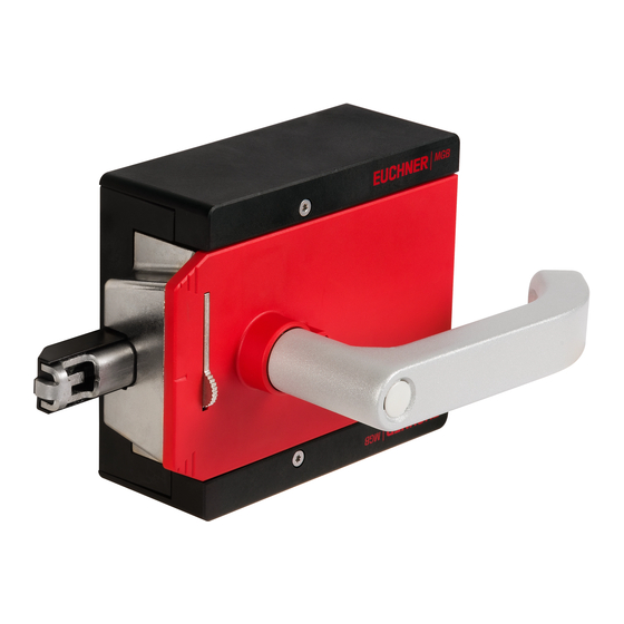
Page 14: System Overview
Operating Instructions Safety Systems MGB2-L..B-PN.-… (PROFINET) 7. System overview Escape release (optional) Locking module (MGB-E-…) (MGB2-L…) Profinet bus module (MBM-…) Handle module (MGB2-H…) Fig. 1: Components at a glance 7.1. Locking module MGB2-L.. Key: • Module function LED indicators • Auxiliary marking for correct alignment in relation to the handle module •... -
Page 15: Handle Module Mgb2-H
Operating Instructions Safety Systems MGB2-L..B-PN.-… (PROFINET) 7.2. Handle module MGB2-H-… Key: • Door handle • Fold-out lockout mechanism • Automatically extending lockout mechanism (optional) • Auxiliary markings for max. permissible mounting distance • Bolt tongue • Locking bolt for handle adjustment Fig. -
Page 16: Dimension Drawings
Operating Instructions Safety Systems MGB2-L..B-PN.-… (PROFINET) 7.4. Dimension drawings 7.4.1. Locking module MGB2-L… M12x1 12 max. 7.4.2. Handle module MGB2-H… 16,5 12 max. min. max. (translation of the original operating instructions) 2540773-01-03/23... -
Page 17: Escape Release Mgb-E
Operating Instructions Safety Systems MGB2-L..B-PN.-… (PROFINET) 7.4.3. Escape release MGB-E-… 2540773-01-03/23 (translation of the original operating instructions) -
Page 18: Dimension Drawing For Bus Module Mbm
Operating Instructions Safety Systems MGB2-L..B-PN.-… (PROFINET) 7.4.4. Dimension drawing for bus module MBM 12 max. 12 max. (translation of the original operating instructions) 2540773-01-03/23... -
Page 19: Assembly Of Mgb2-L, Mgb2-H And Mgb-E (Example On Profile 40X40)
Operating Instructions Safety Systems MGB2-L..B-PN.-… (PROFINET) 7.4.5. Assembly of MGB2-L, MGB2-H and MGB-E (example on profile 40x40) ±4 114,2 110,6 ±4 2540773-01-03/23 (translation of the original operating instructions) -
Page 20: Drilling Pattern, Escape Release Mgb-E
Operating Instructions Safety Systems MGB2-L..B-PN.-… (PROFINET) 7.4.6. Drilling pattern, escape release MGB-E MGB-E 86,5 (translation of the original operating instructions) 2540773-01-03/23... -
Page 21: Manual Release
Operating Instructions Safety Systems MGB2-L..B-PN.-… (PROFINET) 8. Manual release Some situations require the guard locking to be released manually (e.g. malfunctions or an emergency). A function test should be performed after release. More information on this topic can be found in the standard EN ISO 14119:2013, section 5.7.5.1. The device can feature the following release functions: 8.1. -
Page 22: Lockout Mechanism
Operating Instructions Safety Systems MGB2-L..B-PN.-… (PROFINET) 8.2. Lockout mechanism If the lockout mechanism is pivoted out, the bolt tongue cannot be extended. The lockout mechanism can be secured with padlocks (see Fig. 6). This is intended to prevent people from being locked in unintentionally. The lockout mechanism does not fulfill any safety function. -
Page 23: Preparing Escape Release
Operating Instructions Safety Systems MGB2-L..B-PN.-… (PROFINET) 8.3.1. Preparing escape release Length required for actuation axis Profile width Without With mounting Which EUCHNER parts are required? Necessary work steps mounting plates plates (4 mm each) D+17 30 mm 39 mm 47 mm... -
Page 24: Mounting
Operating Instructions Safety Systems MGB2-L..B-PN.-… (PROFINET) 9. Mounting IMPORTANT Ì Mounting must be performed only by authorized personnel. Ì Depending on the substrate material, the detection range for the acquisition of the door position may vary. Ì During mounting, pay attention to correct alignment. Use the alignment aids on the housing for the locking module and on the housing for the handle module (see Fig. -
Page 25: Line Swap
Operating Instructions Safety Systems MGB2-L..B-PN.-… (PROFINET) 9.1. Line swap During the first starting process, the current MLI topology will be saved if the control system configuration matches the MLI topology. When the system is restarted, the bus module detects if the position of an MLI device has changed or the device is being operated on a different MLI line. -
Page 26: Replacing Submodules
Operating Instructions Safety Systems MGB2-L..B-PN.-… (PROFINET) Pos. 1 Pos. 2 Pos. 3 Fig. 9: Mounting submodule 9.4. Replacing submodules CAUTION Risk of damage to equipment or malfunction as a result of uncontrolled machine stop. The communication within the system is interrupted by the replacement of a submodule, and the Ì... -
Page 27: Fitting And Removing Lenses And Labels For Controls And Indicators
Operating Instructions Safety Systems MGB2-L..B-PN.-… (PROFINET) 9.4.2. Fitting and removing lenses and labels for controls and indicators Fitting 90° Click! Removing Lens 2540773-01-03/23 (translation of the original operating instructions) -
Page 28: Changing The Door Hinge Position
Operating Instructions Safety Systems MGB2-L..B-PN.-… (PROFINET) 10. Changing the door hinge position 10.1. Changing the locking module to a different door hinge position To change the locking module for doors with a different door hinge position, the module only needs to be rotated by 180°. Submodules installed in the module can also be rotated by 180°... - Page 29 Operating Instructions Safety Systems MGB2-L..B-PN.-… (PROFINET) OPEN CLOSED • Unscrew locking screws. • Push door handle up. • Push cover aside. Fig. 10: Changing actuating direction, step • Fig. 11: Changing actuating direction, steps • and • • Only on the use of an escape release: using the Torx 10, turn the joint counterclockwise from position (a) to position (b).
-
Page 30: Protection Against Environmental Effects
Operating Instructions Safety Systems MGB2-L..B-PN.-… (PROFINET) 11. Protection against environmental effects Lasting and correct safety function requires that the system must be protected against foreign bodies such as swarf, sand, blasting shot, etc., which can become lodged in the locking and handle modules. For this purpose a suitable installation position should be selected. -
Page 31: Bus Module Mbm
Operating Instructions Safety Systems MGB2-L..B-PN.-… (PROFINET) 12.2. Bus module MBM 12.2.1. DIP switches The DIP switches have the following functions: Setting the device’s PROFIsafe address Ì Hardware reset to restore the device to the factory settings Ì Activating the device web interface Ì... -
Page 32: Electrical Connection
Operating Instructions Safety Systems MGB2-L..B-PN.-… (PROFINET) 13. Electrical connection WARNING In the event of a fault, loss of the safety function due to incorrect connection. Mounting must be performed only by authorized personnel. Ì Lay the connecting cables with protection to prevent the risk of short circuits. Ì... -
Page 33: Bus Connections
Operating Instructions Safety Systems MGB2-L..B-PN.-… (PROFINET) 13.2. Bus connections The bus module MBM includes the PROFINET connections (XF1 and XF2) and the power supply connections (XD1 and XD2). Connection is performed via push-pull plugs according to IEC 61076-3-117, variant 14. The bus module MBM includes a PROFINET IRT switch for Ethernet connection. 13.2.1. -
Page 34: Remote Mounting
Operating Instructions Safety Systems MGB2-L..B-PN.-… (PROFINET) 13.3.2. Remote mounting Pay attention to the following points on remote mounting: The maximum cable length for a line must not exceed 40 m. Ì Up to 3 modules can be operated per line. If you require a different configuration, contact our technical support team. Ì... -
Page 35: Setup
Operating Instructions Safety Systems MGB2-L..B-PN.-… (PROFINET) 14. Setup 14.1. Teach-in operation (only for MGB2 unicode) The handle module must be assigned to the locking module using a teach-in function before the system comprising locking module and handle module forms a functional unit. During a teach-in operation, the module is in the safe state (no safe bits are set). -
Page 36: Integrating Into Profinet And Profisafe
Alternatively, the following GSD file in GSDML format can also be used: GSDML-Vx.x-Euchner-MGB-PN_D_YYYYMMDD.xml Ì You will find the GSD file in the Download area at www.euchner.com. Prior to setup, the GSD file must be imported into the configuration software for the control system (see control system manual). -
Page 37: List Of The Parameters That Can Be Set Per Module/Submodule
Operating Instructions Safety Systems MGB2-L..B-PN.-… (PROFINET) 14.2.1. List of the parameters that can be set per module/submodule PROFINET, Setting range / [factory Module/submodule Parameter Description PROFIsafe setting] Bus module MBM PROFINET Device name Arbitrary designation The device name can be assigned as required. Important: It must match the name in the configuration software. -
Page 38: Replacing An Mgb2 System Without Programming Device
Operating Instructions Safety Systems MGB2-L..B-PN.-… (PROFINET) 14.3. Replacing an MGB2 system without programming device If servicing is required, the MGB2 system is easy to replace with a new one. For this purpose, the following prerequisites must be met: The DIP switch settings (PROFIsafe address) on the new device must match those on the old device. Ì... -
Page 39: Profinet Data Bytes For Data Structure (Data Blocks For Non-Safe Functions)
Operating Instructions Safety Systems MGB2-L..B-PN.-… (PROFINET) 14.6. PROFINET data bytes for data structure (data blocks for non-safe functions) Important! Select one of the configurations by bringing together the corresponding modules via drag & drop in the configuration software of your control system. The modules are easy to distinguish by means of the commentary block. -
Page 40: Data Blocks For Mgb2 Modules
Operating Instructions Safety Systems MGB2-L..B-PN.-… (PROFINET) 14.7. Data blocks for MGB2 modules All standard functions of an MGB2 module are combined in these data blocks. Additional functions, e.g. an optional enabling switch or a stack light, have separate data areas. 14.7.1. -
Page 41: Non-Safe Bits
Operating Instructions Safety Systems MGB2-L..B-PN.-… (PROFINET) 14.7.2. Non-safe bits Input Bit identifier Meaning Condition for setting Condition for resetting Non-safe input Door closed and bolt tongue inserted Bolt tongue not in locking module Bolt position into locking module OR error Non-safe input Door closed Door open OR error... -
Page 42: Additional Button Functions
Operating Instructions Safety Systems MGB2-L..B-PN.-… (PROFINET) 14.7.4. Additional button functions Lamp control in enabling switch with MGB2-PN Lamp Color Flashing Enabling switch inserted Enabling switch not inserted Enabling switch inserted and Enabling switch not pressed or Enabling switch inserted and Yellow pressed and acknowledged enabling switch not inserted... -
Page 43: Profisafe Data Bytes (Data Block For Safe Functions)
Operating Instructions Safety Systems MGB2-L..B-PN.-… (PROFINET) 14.8. PROFIsafe data bytes (data block for safe functions) Safe PROFIsafe data are transmitted in addition to the non-safe PROFINET data. These data include all information about the door position and guard locking, emergency stop and enabling switch, for example. Important! Select one of the configurations by bringing together the corresponding modules via drag &... -
Page 44: Safe Bits
Operating Instructions Safety Systems MGB2-L..B-PN.-… (PROFINET) 14.8.3. Safe bits Input/output Bit identifier Meaning Condition for setting Condition for resetting Safe input Door closed and bolt tongue inserted Door open OR error Door position into locking module Safe input Door closed, bolt tongue inserted Guard locking open OR error Guard lock monitoring into locking module and locked... -
Page 45: Diagnostics, Troubleshooting And Aids
Operating Instructions Safety Systems MGB2-L..B-PN.-… (PROFINET) 15. Diagnostics, troubleshooting and aids All error codes are listed in the following. The error code is output in the corresponding byte. Important! The error code given in the tables below is sequential and starts with 0x01. You must add any upstream error codes from PROFINET or the control system to the error codes stated. -
Page 46: Diagnostics With The Aid Of The Device Web Interface
Operating Instructions Safety Systems MGB2-L..B-PN.-… (PROFINET) 15.4. Diagnostics with the aid of the device web interface The device has an internal device web interface. The device web interface can be used at any time in operation if the function is activated. It is not possible to make any settings on the device. The following diagnostics information is provided: Overview of all modules and submodules installed Ì... - Page 47 The download link is at the end of the error list. Click ENVIRONMENT to display available environment parameters. The password-protected SERVICE page can be accessed only for on-site support by EUCHNER. Ì...
-
Page 48: System Indications During Setup, Teach-In And Normal Operation
Operating Instructions Safety Systems MGB2-L..B-PN.-… (PROFINET) 15.5. System indications during setup, teach-in and normal operation Guard locking status (ÜK) Safe input bit LM.FI_UK Status bit LM.I_UK Guard locking Status bit LM.I_OL Bolt position (SK) Safe input bit LM.FI_SK Status bit LM.I_SK Bolt position Status bit LM.I_OT Device diagnostics Status bit LM.I_OD... -
Page 49: General Errors
Operating Instructions Safety Systems MGB2-L..B-PN.-… (PROFINET) 15.6. General errors LED displays Bus module 0x01 Internal error Internal device Internal Latching Restart system. If the … error. Device is no error error persists, contact BM_E_G 0x06 longer functional. our support team. Interlocking/locking module LED displays Interlocking/locking module... -
Page 50: Teach-In Errors And Configuration Errors
Operating Instructions Safety Systems MGB2-L..B-PN.-… (PROFINET) 15.7. Teach-in errors and configuration errors LED displays Bus module Configuration Configuration Config- Latching Restore the correct error in the control uration configuration and system does not error restart the system. A match the actual factory reset may be 0xAE BM_E_G... -
Page 51: Transponder Errors
Operating Instructions Safety Systems MGB2-L..B-PN.-… (PROFINET) 15.8. Transponder errors LED displays Interlocking/locking module Invalid handle Handle module is Transponder Latching Restart teach-in operation. If module detected not valid or handle error the error persists, contact our 0x42 LM_E_G module is faulty. support team. - Page 52 Operating Instructions Safety Systems MGB2-L..B-PN.-… (PROFINET) Interlocking/locking module LED displays Interlocking/locking module Supply voltage Overvoltage Environment Resetta- Decrease supply voltage. Pay 0x60 too high error attention to technical data. Supply voltage Low voltage Environment Resetta- Increase supply voltage or too low error check system topology.
-
Page 53: Communication Errors
Operating Instructions Safety Systems MGB2-L..B-PN.-… (PROFINET) 15.10. Communication errors LED displays Bus module Commu- Check cables and plug Communication Resetta- 0x74 MLI1 disrupted nication connectors for correct disrupted error seating and damage. Commu- Check cables and plug Communication Resetta- 0x75 MLI2 disrupted nication connectors for correct... -
Page 54: Plausibility Errors
Operating Instructions Safety Systems MGB2-L..B-PN.-… (PROFINET) 15.11. Plausibility errors LED displays Interlocking/locking module Plausibility error: Transponder for Plausibility error Resetta- Check function of the handle bolt fracture the bolt has been module. Pay attention to detected without the damage. Replace handle 0x88 door closed. -
Page 55: Profinet Errors
Operating Instructions Safety Systems MGB2-L..B-PN.-… (PROFINET) 15.13. PROFINET errors LED displays Bus module Parameter The assembly Applica- Latching Check setting error has detected a tion error parameters parameter setting and correct error. these. Then Parameter setting load the errors can be: parameters - The assembly into the... -
Page 56: Profisafe Errors
Operating Instructions Safety Systems MGB2-L..B-PN.-… (PROFINET) 15.14. PROFIsafe errors LED displays Bus module F_DEST_ Erroneous Param- Latch- The PROFIsafe address ADDR safety eter set on the device does not destination setting match the address set in the address error configuration tool for your 0x0150 control system. - Page 57 Operating Instructions Safety Systems MGB2-L..B-PN.-… (PROFINET) LED displays Bus module F_Block_ID not Param- Reset- Check the parameters and supported eter table correct them. Then load the 0x0162 setting parameters into the assembly error again. CRC2 Commu- Reset- Read the CRC2 error memory. 0x0163 error nication...
-
Page 58: Technical Data
Operating Instructions Safety Systems MGB2-L..B-PN.-… (PROFINET) 16. Technical data NOTICE If a data sheet is included with the product, the information on the data sheet applies. Parameter Value Housing material Fiber glass reinforced plastic Die-cast zinc, nickel-plated, stainless steel, powder-coated sheet steel Dimensions See dimension drawing Weight of MGB2-L.B (bus module, locking module and submodules with mounting... -
Page 59: Radio Frequency Approvals
Operating Instructions Safety Systems MGB2-L..B-PN.-… (PROFINET) - MBM 5.38 x 10 - Monitoring of guard locking and the position of the guard 2.62 x 10 - Monitoring of the position of the guard 2.62 x 10 - Evaluation of safety signals in submodules installed 2.62 x 10 - MSM for enabling switch 2.16 x 10... -
Page 60: Troubleshooting
Operating Instructions Safety Systems MGB2-L..B-PN.-… (PROFINET) 17. Troubleshooting 17.1. Fault on actuating the escape release To achieve monitoring of the locking element in category 4, PL e according to EN ISO 13849-1, internal monitoring logic is integrated into every locking module. Result: Bit I0_1 is set in the diagnostic block when the escape release is actuated (see 15. Diagnostics, troubleshooting and aids on page 45). -
Page 61: Service
20. Declaration of conformity The declaration of conformity is part of the operating instructions. The complete EU declaration of conformity can also be found at www.euchner.com. Enter the order number of your device in the search box. The document is available under Downloads. - Page 62 Operating Instructions Safety Systems MGB2-L..B-PN.-… (PROFINET) (translation of the original operating instructions) 2540773-01-03/23...
- Page 63 Operating Instructions Safety Systems MGB2-L..B-PN.-… (PROFINET) 2540773-01-03/23 (translation of the original operating instructions)
- Page 64 2540773-01-03/23 Title: Operating Instructions Safety Systems MGB2-L..B-PN.-… (PROFINET) and from V3.30.1 (translation of the original operating instructions) Copyright: © Euchner GmbH + Co. KG, 03/2023 Subject to technical modifications; no responsibility is accept- ed for the accuracy of this information.
Need help?
Do you have a question about the MGB2-L B-PN Series and is the answer not in the manual?
Questions and answers