Table of Contents
Advertisement
Quick Links
Advertisement
Table of Contents

Related Manuals for EUCHNER MGBS-P-I-AP Series


Summary of Contents for EUCHNER MGBS-P-I-AP Series
- Page 1 Operating Instructions Safety System MGBS-P-I-AP… Unicode/Multicode...
-
Page 2: Table Of Contents
Operating Instructions Safety System MGBS-P-I-AP… Contents About this document ..................... 4 1.1. Scope ............................4 1.2. Target group ..........................4 1.3. Key to symbols ..........................4 1.4. Supplementary documents ......................4 Correct use ......................5 Description of the safety function ................6 Exclusion of liability and warranty ................. 7 General safety precautions ................... - Page 3 Operating Instructions Safety System MGBS-P-I-AP… Setup ......................... 21 12.1. LED displays ..........................21 12.2. Teach-in function for handle module (only for unicode evaluation) ............21 12.2.1. Teaching in handle module .....................22 4.1. Functional check ...........................22 4.1.1. Mechanical function test ....................22 4.1.2. Electrical function test ....................22 System status table ....................
-
Page 4: About This Document
Important! Always read all documents to gain a complete overview of safe installation, setup and use of the device. The documents can be downloaded from www.euchner.com. For this purpose enter the doc. no. in the search box. (Translation of the original operating instructions) 2527247-01-09/19... -
Page 5: Correct Use
Ì EN 60204-1 The interlocking module is allowed to be operated only in conjunction with the intended EUCHNER handle module and the related connection components from EUCHNER. On the use of other handle modules or other connection components, EUCHNER provides no warranty for safe function. -
Page 6: Description Of The Safety Function
Operating Instructions Safety System MGBS-P-I-AP… Table 1: Possible combinations for MGBS components Handle module Interlocking module MGBS-H… MGBS… Key to symbols Combination possible 3. Description of the safety function Devices from this series feature the following safety functions: Monitoring of the guard position (interlocking device according to EN ISO 14119) Ì... -
Page 7: Exclusion Of Liability And Warranty
Prior to use, read the operating instructions and keep these in a safe place. Ensure the operating instructions are always available during mounting, setup and servicing. EUCHNER cannot provide any warranty in relation to the readability of the CD for the storage period required. For this reason you should archive a printed copy of the operating instructions. -
Page 8: Function
Operating Instructions Safety System MGBS-P-I-AP… 6. Function The device monitors the position of movable guards. The system consists of the following components: coded handle module (transponder) and interlocking module. Whether the device learns the complete transponder code (unicode) or not (multicode) depends on the respective version. -
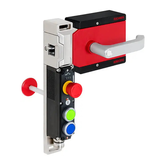
Page 9: System Overview
Operating Instructions Safety System MGBS-P-I-AP… 7. System overview 7.1. MGBS-P-I-… Key: 1 Interlocking module 2 Optionally with Extended version NOTICE Ì Depending on the version, additional controls and indicators may be integrated. Ì Depending on the version, a mounting plate can be included. -
Page 10: Dimension Drawing (Example Illustration)
Operating Instructions Safety System MGBS-P-I-AP… 4,15 89,4 89,4 109,4 Square drive Profile 55,5 11,5 62,3 22,2 115,5 114,3 (Translation of the original operating instructions) 2527247-01-09/19... -
Page 11: Drilling Pattern (Example Illustration)
Operating Instructions Safety System MGBS-P-I-AP… 2527247-01-09/19 (Translation of the original operating instructions) -
Page 12: Manual Release
8. Manual release 8.1. Escape release MGB-E-… (optional) MGBS-H...-L-... MGB-E-... MGBS-H...-R-... MGBS-P-I-AP... 8.1.1. Preparing escape release Profile width Length required for actuation Which EUCHNER parts are required? Necessary work steps axis Without With mounting mounting plates plates (4 mm each) D+17... -
Page 13: Lockout Mechanism
Operating Instructions Safety System MGBS-P-I-AP… 1 Insert actuation axis. Standard Extended Standard Extended Example without mounting plates protective protective actuation axis actuation axis The snap ring A must be in contact sleeve sleeve with the inner door handle B. 2 Fit door handle. Escape release 3 Tighten fixing screw to 2 Nm. -
Page 14: Changing Actuating Direction Of The Interlocking Module
Operating Instructions Safety System MGBS-P-I-AP… 9. Changing actuating direction of the interlocking module NOTICE Ì Please read the operating instructions of the device before use! Ì If a data sheet is included with the product, the information on the data sheet applies. Ì... -
Page 15: Mounting
Operating Instructions Safety System MGBS-P-I-AP… 10. Mounting CAUTION Interlocking modules must not be bypassed (bridging of contacts), turned away, removed or otherwise rendered ineffective. Ì Observe EN ISO 14119:2013, section 7, for information about reducing the possibilities for by- passing an interlocking device. NOTICE Risk of damage to equipment and malfunctions as a result of incorrect installation. -
Page 16: Electrical Connection
Operating Instructions Safety System MGBS-P-I-AP… 11. Electrical connection WARNING If there is a mistake, loss of the safety function due to incorrect connection. Ì To ensure safety, both safety outputs (FO1A and FO1B) must always be evaluated. Ì Monitoring outputs must not be used as safety outputs. Ì... -
Page 17: Safety In Case Of Faults
Ì On the use of other connection components, the requirements in the following table apply. EUCHNER provides no warranty for safe function in case of failure to comply with these require- ments. Observe the following requirements with respect to the connecting cables: For interlocking modules MGBS-…-AP-…-SAB-…... -
Page 18: Connector Assignment Of Interlocking Modules Mgbs
Operating voltage of AP electronics 24 V DC FO1A Safety output, channel 1 FO1B Safety output, channel 2 Diagnostic output Door monitoring output Operating voltage of AP electronics 0 V n.c. 1) Only for standard EUCHNER connecting cable. (Translation of the original operating instructions) 2527247-01-09/19... -
Page 19: Connection Of Mgbs-I-Ap
Detailed application examples can be found at www.euchner.com. Simply enter the order number of your interlocking module in the search box. All available connection examples for the device can be found in “Downloads.”... -
Page 20: Notes On Operation With Safe Control Systems
Technical data on page 24. A detailed example of connecting and setting the parameters of the control system is available for many devices at www.euchner.com in the area Download Applications MGBS. The features of the respective device are dealt with there ¨... -
Page 21: Setup
Operating Instructions Safety System MGBS-P-I-AP… 12. Setup 12.1. LED displays You will find a detailed description of the signal functions in chapter 5. System status table on page 23. Color STATE green STATE 12.2. Teach-in function for handle module (only for unicode evaluation) The handle module must be assigned to the interlocking module using a teach-in function before the system forms a func- tional unit. -
Page 22: Teaching In Handle Module
Operating Instructions Safety System MGBS-P-I-AP… 12.2.1. Teaching in handle module 1. Establish teach-in standby: - Devices in the condition as supplied: unlimited teach-in standby after switching on - Interlocking module already taught in: teach-in standby is available for approx. 3 min. after switching on Teach-in standby indication, STATE LED flashes 3x repeatedly ¨... -
Page 23: System Status Table
Operating Instructions Safety System MGBS-P-I-AP… 5. System status table LED display Output Operating mode State closed Normal operation, door closed Normal operation open Normal operation, door open open Device in teach-in standby Teach-in operation closed 1 Hz Teach-in operation (only unicode) ... -
Page 24: Technical Data
Operating Instructions Safety System MGBS-P-I-AP… 6. Technical data NOTICE If a data sheet is included with the product, the information on the data sheet applies. 6.1. Technical data for interlocking module MGBS-P-I-AP Parameter Value Unit min. typ. max. General Material of interlocking module - Head Die-cast zinc - Housing... -
Page 25: Typical System Times
Operating Instructions Safety System MGBS-P-I-AP… 6.1.1. Typical system times Please refer to the technical data for the exact values. Ready delay: After switch-on, the device carries out a self-test. The system is ready for operation only after this time. Switch-on time of safety outputs: The max. reaction time t is the time from the moment when the guard is closed to the moment when the safety outputs switch on. -
Page 26: Radio Frequency Approvals
(2) l’utilisateur de l’appareil doit accepter tout brouillage radioélectrique subi, même si le brouillage est susceptible d’en compromettre le fonctionnement. Supplier‘s Declaration of Conformity 47 CFR § 2.1077 Compliance Information Unique Identifier: MGBS-P-I-AP SERIES MGBS-P-I1-AP SERIES MGBS-P-I2-AP SERIES MGBS-P-IBI-AP SERIES MGBS-P-L1-AP SERIES... -
Page 27: Dimension Drawings Of Variants
Operating Instructions Safety System MGBS-P-I-AP… 6.4. Dimension drawings of variants Plug connectors 2 x M12 Plug connector M23 Cable exit C Cable exit A Cable exit C Cable exit A 2527247-01-09/19 (Translation of the original operating instructions) -
Page 28: Ordering Information And Accessories
7. Ordering information and accessories Tip! Suitable accessories, e.g. cables or assembly material, can be found at www.euchner.com. To order, enter the order number of your item in the search box and open the item view. Accessories that can be combined with the item are listed in “Accessories.”... -
Page 29: Declaration Of Conformity
Operating Instructions Safety System MGBS-P-I-AP… 10. Declaration of conformity 2527247-01-09/19 (Translation of the original operating instructions) - Page 30 Operating Instructions Safety System MGBS-P-I-AP… (Translation of the original operating instructions) 2527247-01-09/19...
- Page 31 Operating Instructions Safety System MGBS-P-I-AP… 2527247-01-09/19 (Translation of the original operating instructions)
- Page 32 70771 Leinfelden-Echterdingen info@euchner.de www.euchner.com Edition: 2527247-01-09/19 Title: Operating Instructions Safety System MGBS-P-I-AP… (Translation of the original operating instructions) Copyright: © EUCHNER GmbH + Co. KG, 09/2019 Subject to technical modifications; no responsibility is accept- ed for the accuracy of this information.
Need help?
Do you have a question about the MGBS-P-I-AP Series and is the answer not in the manual?
Questions and answers