Table of Contents
Advertisement
Quick Links
Advertisement
Table of Contents

Related Manuals for EUCHNER MGBS-P-L1H-AR-U-L-SH-161564


Summary of Contents for EUCHNER MGBS-P-L1H-AR-U-L-SH-161564
- Page 1 Operating Instructions Safety System MGBS-P-L.-AR… Unicode/Multicode...
-
Page 2: Table Of Contents
Operating Instructions Safety System MGBS-P-L.-AR… Contents About this document ..................... 4 1.1. Scope ............................4 1.2. Target group ..........................4 1.3. Key to symbols ..........................4 1.4. Supplementary documents ......................4 Correct use ......................5 Description of the safety function ................6 Exclusion of liability and warranty ................. 8 General safety precautions ................... - Page 3 Operating Instructions Safety System MGBS-P-L.-AR… Mounting ......................19 10.1. Mounting examples ........................19 10.2. Actuating escape release ......................20 Electrical connection ..................21 11.1. Notes about .........................22 11.2. Safety in case of faults ........................22 11.3. Fuse protection for power supply ....................22 11.4. Requirements for connecting cables ....................23 11.5.
-
Page 4: About This Document
Important! Always read all documents to gain a complete overview of safe installation, setup and use of the device. The documents can be downloaded from www.euchner.com. For this purpose enter the doc. no. in the search box. (translation of the original operating instructions) 2527246-03-06/23... -
Page 5: Correct Use
Ì EN 60204-1 The safety system MGBS is only allowed to be operated in conjunction with the intended EUCHNER handle modules and the related connection components and accessories from EUCHNER. On the modification of system components, EUCHNER provides no warranty for function. -
Page 6: Description Of The Safety Function
Operating Instructions Safety System MGBS-P-L.-AR… Table 1: Possible combinations for MGBS components Handle module Locking module MGBS-H… MGBS… Key to symbols Combination possible NOTICE For information about combination with an AR evaluation unit, please refer to chapter 11.10. Connection of several MGBS‑AR in a switch chain on page 28. 3. - Page 7 Operating Instructions Safety System MGBS-P-L.-AR… Control of guard locking (applies only to guard locking devices according the closed-circuit current principle) If the device is used as guard locking for personnel protection, control of guard locking must be regarded as a safety function. The device does not feature a safety characteristic for control of guard locking, because the guard locking solenoid is completely disconnected from outside the device (no control function within the device).
-
Page 8: Exclusion Of Liability And Warranty
Prior to use, read the operating instructions and keep these in a safe place. Ensure the operating instructions are always available during mounting, setup and servicing. EUCHNER cannot provide any warranty in relation to the readability of the CD for the storage period required. For this reason you should archive a printed copy of the operating instructions. -
Page 9: Function
Operating Instructions Safety System MGBS-P-L.-AR… 6. Function The device permits the locking of movable guards. The system consists of the following components as a minimum: coded handle module (transponder) and locking module. Whether the locking module learns the complete transponder code (unicode) or not (multicode) depends on the respective version. -
Page 10: Guard Locking For Version Mgbs-L2
Operating Instructions Safety System MGBS-P-L.-AR… Important! If the guard is open when the power supply is interrupted and is then closed, guard locking is activated. This can lead to persons being locked in unintentionally. The tongue on the handle module cannot be pulled out of the locking module and the guard is locked as long as the guard locking pin is extended. -
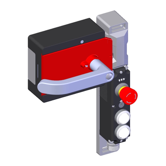
Page 11: System Overview
Operating Instructions Safety System MGBS-P-L.-AR… 7. System overview 7.1. MGBS-P-… (optionally with escape release) Key: • Locking module or interlocking module • Optionally with escape release • Optionally with Extended version NOTICE Ì Depending on the version, additional controls and indicators may be integrated. -
Page 12: Dimension Drawing (Example Illustration)
Operating Instructions Safety System MGBS-P-L.-AR… 4,65 104,4 89,4 89,4 Square drive 55,5 11,5 Profile 62,3 115,5 22,2 (translation of the original operating instructions) 2527246-03-06/23... -
Page 13: Drilling Pattern (Example Illustration)
Operating Instructions Safety System MGBS-P-L.-AR… 2527246-03-06/23 (translation of the original operating instructions) -
Page 14: Manual Release
Operating Instructions Safety System MGBS-P-L.-AR… 8. Manual release Important! No further release functions can be retrofitted on Extended variants with control elements in position 1 (S1) and position 2 (S2). Some situations require the guard locking to be released manually (e.g. malfunctions or an emergency). A function test should be performed after release. -
Page 15: Emergency Release
Operating Instructions Safety System MGBS-P-L.-AR… 8.2. Emergency release This permits opening of a locked guard from outside the danger zone without tools. For mounting, see the mounting sup- plement. Important! Ì It must be possible to operate the emergency release manually from outside the protected area without tools. -
Page 16: Preparation For Inner Door Handle Ae-R-S1
8.3.2. Preparation for inner door handle AE-R-S1 NOTICE Various inner door handles with different axis lengths are available, as well as mounting plates and door handles/door knobs. You will find further information at www.euchner.com. Length required for actuation axis Profile width... -
Page 17: Lockout Mechanism
Operating Instructions Safety System MGBS-P-L.-AR… 8.4. Lockout mechanism The lockout mechanism can be secured with padlocks (see Fig. 1). This is intended to prevent people from being locked in unintentionally. The lockout mechanism does not fulfill any safety function. Key: •... -
Page 18: Changing Actuating Direction Of The Locking Module
Operating Instructions Safety System MGBS-P-L.-AR… 9. Changing actuating direction of the locking module NOTICE Ì Please read the operating instructions of the device before use! Ì If a data sheet is included with the product, the information on the data sheet applies. Ì... -
Page 19: Mounting
Operating Instructions Safety System MGBS-P-L.-AR… 10. Mounting CAUTION Locking modules must not be bypassed (bridging of contacts), turned away, removed or otherwise rendered ineffective. Ì Observe EN ISO 14119:2013, section 7, for information about reducing the possibilities for bypassing an interlocking device. NOTICE Risk of damage to equipment and malfunctions as a result of incorrect installation. -
Page 20: Actuating Escape Release
Operating Instructions Safety System MGBS-P-L.-AR… 10.2. Actuating escape release • Press the red release knob to the end stop. Guard locking is released. ¨ • Actuate inner door handle (translation of the original operating instructions) 2527246-03-06/23... -
Page 21: Electrical Connection
The following connection options are available: Ì Separate operation Ì Series connection with Y-distributors from EUCHNER (only with M12 plug connector) Ì Series connection, e.g. with wiring in the control cabinet Ì Operation on an AR evaluation unit (not for MGBS Extended). -
Page 22: Notes About
Operating Instructions Safety System MGBS-P-L.-AR… 11.1. Notes about Important! Ì This device is intended to be used and applied with a Class 2 power source. Alternative solutions must comply with the following requirements: This device shall be used with a suitable isolating source in conjunction with a fuse in accordance with UL248. -
Page 23: Requirements For Connecting Cables
Use connection components and connecting cables from EUCHNER. Ì On the use of other connection components, the requirements in the following table apply. EUCHNER provides no warranty for safe function in case of failure to comply with these requirements. Observe the following requirements with respect to the connecting cables: For locking modules MGBS-…-AR-…-SAB-…... -
Page 24: Maximum Cable Lengths
Operating Instructions Safety System MGBS-P-L.-AR… 11.5. Maximum cable lengths Switch chains are permitted up to a maximum overall cable length of 200 m taking into account the voltage drop as a result of the cable resistance (see table below with example data and case example). =200 m = 24 V -20% = 24 V -10%... -
Page 25: Determining Cable Lengths Using The Example Table
Operating Instructions Safety System MGBS-P-L.-AR… 11.5.1. Determining cable lengths using the example table Example: 6 locking modules are to be used in series. Cabling with a length of 40 m is routed from a safety relay in the control cabinet to the last locking module (#6). Cables with a length of 20 m each are connected between the individual locking modules CES-AR/MGBS-L1-…... -
Page 26: Connector Assignment Of Locking Module Mgbs
Door position monitoring output X 2.3 Diagnostic monitoring output X 2.4 Solenoid operating voltage, 24 V DC X 2.5 n.c. 1) Only for standard EUCHNER connecting cable 11.7. Connector assignment of locking module MGBS-…-AR-…-SH-… with plug connector M23 (RC18) Wiring diagram B Conductor color- Plug connector... -
Page 27: Connector Assignment For Y-Distributor
Operating Instructions Safety System MGBS-P-L.-AR… 11.8. Connector assignment for Y-distributor (only for version with plug connectors 2 x M12) Important! The switch chain must always be terminated with strapping plug 097645. Connector assignment for lock- ing module MGBS-L1-… (plug X1, 8-pin plug) and Y-distributor (8-pin socket) Function X1.1... -
Page 28: Connection Of A Single Mgbs-Ar
The user is responsible for safe integration into the overall system. Detailed application examples can be found at www.euchner.com. Simply enter the order number of your locking module in the search box. You will find all available connection examples for the device in Downloads. - Page 29 Operating Instructions Safety System MGBS-P-L.-AR… The safety outputs are permanently assigned to the respective safety inputs of the downstream locking module. FO1A must be routed to FI1A and FO1B to FI1B. If the connections are interchanged (e.g. FO1A to FI1B), the device will enter the fault state.
-
Page 30: Notes On Operation On An Ar Evaluation Unit
Ì Always connect inputs FI1A and FI1B directly to a power supply unit or to outputs FO1A and FO1B of another EUCHNER AR device (series connection). Pulsed signals must not be present at inputs FI1A and FI1B. -
Page 31: Connection Of Guard Locking Control
Operating Instructions Safety System MGBS-P-L.-AR… 11.13. Connection of guard locking control 11.13.1. Guard locking control for variants with IMM connection Guard locking solenoid operating voltage, 24 V DC Guard locking solenoid operating voltage, 0 V DC Fig. 8: Connection example with IMM connection 11.13.2. Guard locking control for variants without IMM connection Guard locking solenoid operating voltage, 24 V DC Electronics operating voltage and guard locking... -
Page 32: Setup
Operating Instructions Safety System MGBS-P-L.-AR… 12. Setup 12.1. LED displays You will find a detailed description of the signal functions in chapter 13. System status table on page 35. Color STATE Green LOCK Yellow STATE LOCK 12.2. Teach-in function for handle module (only for unicode evaluation) The handle module must be assigned to the locking module using a teach-in function before the system forms a functional unit. -
Page 33: Teaching-In Handle Module
Operating Instructions Safety System MGBS-P-L.-AR… 12.2.1. Teaching-in handle module 1. Establish teach-in standby: - Devices in the condition as supplied: unlimited teach-in standby after switching on - Locking module already taught-in: teach-in standby is available for approx. 3 min. after switching on Teach-in standby indication, STATE LED flashes 3x repeatedly. -
Page 34: Functional Check
Operating Instructions Safety System MGBS-P-L.-AR… 12.3. Functional check WARNING Danger of fatal injury as a result of faults in installation and the functional check. Ì Before carrying out the functional check, make sure that there are no persons in the danger zone. Ì... -
Page 35: System Status Table
Operating Instructions Safety System MGBS-P-L.-AR… 13. System status table LED indicator Output Operating mode State 5 Hz Self-test Self-test after power-up (10 s) closed Normal operation, door closed and locked Normal operation, door closed and locked, safety outputs not 1 x switched because: closed - Preceding device in the switch chain signals door open (only verse... - Page 36 Operating Instructions Safety System MGBS-P-L.-AR… Important! If you do not find the displayed device status in the system status table, this indicates an internal device fault. In this case, you should contact the manufacturer. (translation of the original operating instructions) 2527246-03-06/23...
-
Page 37: Technical Data
Operating Instructions Safety System MGBS-P-L.-AR… 14. Technical data NOTICE If a data sheet is included with the product, the information on the data sheet applies. 14.1. Technical data for locking module MGBS-AR Value Parameter Unit min. typ. max. General Material - Switch head Die-cast zinc - Switch housing... - Page 38 Operating Instructions Safety System MGBS-P-L.-AR… Value Parameter Unit min. typ. max. Monitoring outputs OL, OI, OD p-switching, short circuit-proof Output voltage 0.8 x UB V DC Max. load Solenoid Solenoid operating voltage IMP (reverse polarity protected, DC 24 V +10%/-15% regulated, residual ripple < 5%) Solenoid current consumption I Connection rating Duty cycle...
-
Page 39: Typical System Times
Operating Instructions Safety System MGBS-P-L.-AR… 14.1.1. Typical system times Please refer to the technical data for the exact values. Ready delay: After switch-on, the device carries out a self-test. The system is ready for operation only after this time. Turn-on time of safety outputs: The max. reaction time t is the time from the moment when the guard is locked to the moment when the safety outputs switch on. -
Page 40: Radio Frequency Approvals
MGBS-P-I1-AP SERIES MGBS-P-I2-AP SERIES MGBS-P-IBI-AP SERIES MGBS-P-L1-AP SERIES MGBS-P-L2-AP SERIES MGBS-P-LBI-AP SERIES Responsible Party – U.S. Contact Information EUCHNER USA Inc. 1860 Jarvis Avenue Elk Grove Village, Illinois 60007 +1 315 701-0315 info(at)euchner-usa.com http://www.euchner-usa.com (translation of the original operating instructions) 2527246-03-06/23... -
Page 41: Dimension Drawings Of Variants
Operating Instructions Safety System MGBS-P-L.-AR… 14.3. Dimension drawings of variants Plug connectors 2 x M12 Plug connector M23 Cable exit C Cable exit A Cable exit C Cable exit A 2527246-03-06/23 (translation of the original operating instructions) - Page 42 Operating Instructions Safety System MGBS-P-L.-AR… With auxiliary key release With release, automatic return max. 50 With emergency release With wire front release (bowden) 21,5 32,4 (translation of the original operating instructions) 2527246-03-06/23...
-
Page 43: Ordering Information And Accessories
Internet: www.euchner.com 18. Declaration of conformity The EU declaration of conformity can be found at www.euchner.com. Enter the order number of your device in the search box. The document is available under Downloads. 2527246-03-06/23 (translation of the original operating instructions) - Page 44 70771 Leinfelden-Echterdingen info@euchner.de www.euchner.com Edition: 2527246-03-06/23 Title: Operating Instructions Safety System MGBS-P-L.-AR… (translation of the original operating instructions) Copyright: © EUCHNER GmbH + Co. KG, 06/2023 Subject to technical modifications; no responsibility is accept- ed for the accuracy of this information.
Need help?
Do you have a question about the MGBS-P-L1H-AR-U-L-SH-161564 and is the answer not in the manual?
Questions and answers