
Related Manuals for EUCHNER MGB-L2B-EIA-L-136525


Summary of Contents for EUCHNER MGB-L2B-EIA-L-136525
- Page 1 Operating Instructions Safety Systems MGB-L..B-EI-… (Ethernet/IP) With Data Structure Type A From V1.5.0...
-
Page 2: Table Of Contents
Operating Instructions Safety Systems MGB-L..B-EI-… (Ethernet/IP) and With Data Structure Type A Contents About this document ..................... 4 1.1. Scope ............................4 1.1.1. Notes on older product versions ..................4 1.2. Target group ..........................4 1.3. Key to symbols ..........................4 1.4. Supplementary documents ......................4 Correct use ...................... - Page 3 Operating Instructions Safety Systems MGB-L..B-EI-… (Ethernet/IP) and With Data Structure Type A Electrical connection ..................22 13.1. Notes about .........................22 13.2. Connections, variant M12 ......................23 13.3. Connections, variant 7/8" ......................23 Setup ......................... 24 14.1. Integrating into Ethernet/IP and CIP Safety ® ........................24 14.2.
-
Page 4: About This Document
Important! Always read all documents to gain a complete overview of safe installation, setup and use of the device. The documents can be downloaded from www.euchner.com. For this purpose enter the doc. no. in the search box. (translation of the original operating instructions) 2126330-11-09/21... -
Page 5: Correct Use
Operating Instructions Safety Systems MGB-L..B-EI-… (Ethernet/IP) and With Data Structure Type A 2. Correct use The following applies to MGB-L0: The system comprises at least one interlocking module MGB-L0-... and one handle module MGB-H... The safety system MGB is an interlocking device without guard locking (type 4). Devices with unicode evaluation possess a high coding level, devices with multicode evaluation possess a low coding level. - Page 6 The safety system MGB can be combined only with the intended modules in the MGB system family. On the modification of system components, EUCHNER provides no warranty for function. The customer is responsible for the safe overall function, especially for the safe integration into the CIP Safety environment.
-
Page 7: Description Of The Safety Function
Operating Instructions Safety Systems MGB-L..B-EI-… (Ethernet/IP) and With Data Structure Type A 3. Description of the safety function Devices from this series feature the following safety functions: The following applies to MGB-L1 and MGB-L2: Monitoring of guard locking and the position of the guard (interlocking device with guard locking according to EN ISO 14119) Ì... - Page 8 Operating Instructions Safety Systems MGB-L..B-EI-… (Ethernet/IP) and With Data Structure Type A The following applies to devices with emergency stop: Emergency stop (emergency stop device according to EN ISO 13850) Ì Safety function: evaluation of emergency stop Ì Safety characteristics: B value for the emergency stop and PFH for the evaluation electronics (see chapter 18.
-
Page 9: Exclusion Of Liability And Warranty
Prior to use, read the operating instructions and keep these in a safe place. Ensure the operating instructions are always available during mounting, setup and servicing. For this reason you should archive a printed copy of the operating instructions. You can download the operating instructions from www.euchner.com. 2126330-11-09/21 (translation of the original operating instructions) -
Page 10: Function
Operating Instructions Safety Systems MGB-L..B-EI-… (Ethernet/IP) and With Data Structure Type A 6. Function 6.1. Interlocking module MGB-L0.B-EI. Together with a handle module, the interlocking module makes it possible to interlock movable guards. The combination also serves as a mechanical door stop at the same time. Important! To operate the device as an interlocking device according to EN ISO 14119, the signals for door position (safe bit FI.D) and bolt position (safe bit FI.B) must be polled in a logical AND operator. -
Page 11: Guard Locking For Version Mgb-L1
Operating Instructions Safety Systems MGB-L..B-EI-… (Ethernet/IP) and With Data Structure Type A 6.3. Guard locking for version MGB-L1 (guard locking actuated by spring force and released by power-ON) Activating guard locking: close guard, no voltage at the solenoid (safety bit FO.L = 0). Releasing guard locking: apply voltage to the solenoid (safety bit FO.L = 1). -
Page 12: System Overview
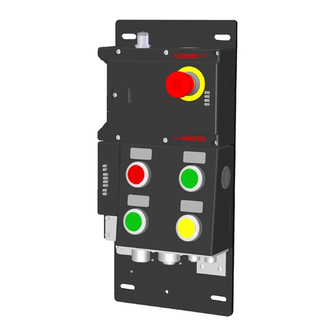
Operating Instructions Safety Systems MGB-L..B-EI-… (Ethernet/IP) and With Data Structure Type A 7. System overview Mounting plate Escape release (optional) (MGB-E...) Locking/release module (MGB-L...) Bus module (Ethernet/IP) (MGB-B...) Handle module (MGB-H...) Fig. 1: Components at a glance NOTICE MGB-EI systems are completely factory configured. The configuration must not be changed subse- quently. -
Page 13: Locking/Release Module Mgb-L
Operating Instructions Safety Systems MGB-L..B-EI-… (Ethernet/IP) and With Data Structure Type A 7.2. Locking/release module MGB-L.- Key: 1 LED indicator 2 Cover for auxiliary release 3 Locking arm (only version with guard locking) 4 Auxiliary marking for max. permitted mounting distance Notice: Depending on version, additional controls and indicators may be integrated into the cover. -
Page 14: Manual Release
Operating Instructions Safety Systems MGB-L..B-EI-… (Ethernet/IP) and With Data Structure Type A 8. Manual release Some situations require the guard locking to be released manually (e.g. malfunctions or an emergency). A function test should be performed after release. More information on this topic can be found in the standard EN ISO 14119:2013, section 5.7.5.1. The device can feature the following release functions: 8.1. -
Page 15: Lockout Mechanism
Operating Instructions Safety Systems MGB-L..B-EI-… (Ethernet/IP) and With Data Structure Type A 8.2. Lockout mechanism If the lockout mechanism is pivoted out/extended, the bolt tongue cannot be extended. The lockout mechanism can be secured with padlocks (see Fig. 7). This is intended to prevent people from being locked in unintentionally. The lockout mechanism does not fulfill any safety function. -
Page 16: Preparing Escape Release
Operating Instructions Safety Systems MGB-L..B-EI-… (Ethernet/IP) and With Data Structure Type A 8.3.1. Preparing escape release Profile width Required length Which EUCHNER parts are required? Necessary work steps Actuation axis Without With mounting mounting plates plates (4 mm each) D+17 30 mm... -
Page 17: Mounting
Tip! Ì You can find various animations about the assembly process in the media library at www.euchner.com. Ì The color and labeling of pushbuttons and indicators can be modified. For mounting steps, see Fig. 9 and Fig. 10 to Fig. 15. -
Page 18: Mounting Lens
Operating Instructions Safety Systems MGB-L..B-EI-… (Ethernet/IP) and With Data Structure Type A Fig. 9: Installation example for door hinged on the right (general view) 9.1. Mounting lens Mounting 90° Click! Removal Lens (translation of the original operating instructions) 2126330-11-09/21... -
Page 19: Changing Actuating Direction
Operating Instructions Safety Systems MGB-L..B-EI-… (Ethernet/IP) and With Data Structure Type A 10. Changing actuating direction (here: from right to left) Important! It is possible to make this change only when the bolt tongue is not extended and an escape release is not yet mounted. -
Page 20: Protection Against Environmental Effects
Operating Instructions Safety Systems MGB-L..B-EI-… (Ethernet/IP) and With Data Structure Type A 3 mm CLOSED 9 Remove cover and undo hexagon socket screw. OPEN AT Change door handle by 90° in clockwise direction and re-fit. A Tighten hexagon socket head screw to 3 Nm. A... -
Page 21: Controls And Indicators
Port disabled IP-Bit 4 Major NIC fault IP-Bit 5 IP-Bit 3 Green flashing No network connection IP-Bit 6 IP-Bit 2 Connection for EUCHNER enabling switch ZSA Green Network connection IP-Bit 7 IP-Bit 1 Red flashing Timeout (order no. 110560) DHCP... -
Page 22: Electrical Connection
Important! Ì The supply for further devices on the bus may be forwarded via the Euchner MGB system. The entire supply current through the MGB must not be higher than specified in chapter 18. Technical data on page 30. -
Page 23: Connections, Variant M12
Operating Instructions Safety Systems MGB-L..B-EI-… (Ethernet/IP) and With Data Structure Type A 13.2. Connections, variant M12 The bus module includes the Ethernet/IP connections (X3 and X4) and the power supply connections (X1 and X2). Connection is via M12 plugs (Ethernet/IP M12 D-coded, power supply M12 A-coded). -
Page 24: Setup
The device can be operated on control systems from firmware version 20.011. Detailed information about setup can be downloaded from www.euchner.com. For this purpose enter application number AP000223 in the search box. An AOI is also available on the Internet. For this purpose enter application number AP000224 in the search box. -
Page 25: Electrical Function Test
Operating Instructions Safety Systems MGB-L..B-EI-… (Ethernet/IP) and With Data Structure Type A 14.4. Electrical function test 1. Switch the operating voltage on or perform a reset via output bit Q.PF in the data block of the diagnostic function. 2. Close all guards and insert the bolt tongue into the locking module. In case of guard locking by solenoid force activate guard locking. - Page 26 Operating Instructions Safety Systems MGB-L..B-EI-… (Ethernet/IP) and With Data Structure Type A Abbr. Name Data Type Safe signal Tag Definition RunMode BOOL Run Mode - Indicates the operating mode of the multifunctional gate box 0 = while restarting 1 = Run Mode after successful restarting of bus module ConnectionFaulted BOOL Connection Faulted - Indicates the state of the communication connection between the multifunctional gate...
-
Page 27: Mgb System Diagnostic Messages
Operating Instructions Safety Systems MGB-L..B-EI-… (Ethernet/IP) and With Data Structure Type A 15. MGB system diagnostic messages All diagnostic messages are listed below. The scope of the possible messages can differ depending on MGB system version. Device-specific diagnostic information Test-pulse error (short-circuit monitoring detected an error) Display via MOD LED (see Fig. -
Page 28: System Status Table
Operating Instructions Safety Systems MGB-L..B-EI-… (Ethernet/IP) and With Data Structure Type A 16. System status table LEDs on interlocking/locking module NOTICE LEDs are not reliable indicators. It is therefore not possible to ensure the correct output of information. Ì For this reason, use the LEDs only for general device diagnostics during setup or fault analysis. Ì... -
Page 29: Special Functions
The MGB firmware can be updated using the ControlFLASH™ software from Rockwell Automation. New firmware updates are available from the EUCHNER support team. Refer to Rockwell Automation Manual 1756-UM105J for more details about using ControlFLASH. ControlFLASH is a trademark of Rockwell Automation, Inc. -
Page 30: Technical Data
Operating Instructions Safety Systems MGB-L..B-EI-… (Ethernet/IP) and With Data Structure Type A 18. Technical data NOTICE If a data sheet is included with the product, the information on the data sheet applies. Parameter Value max. door position 65 mm Housing material Fiber glass reinforced plastic Die-cast zinc, nickel-plated, stainless steel,... -
Page 31: Troubleshooting And Assistance
2. Close guard if necessary and switch on guard locking. The system is in normal operation again. ¨ 19.3. Application examples You will find application examples on connecting the device to various control systems at www.euchner.com. 2126330-11-09/21 (translation of the original operating instructions) -
Page 32: Inspection And Service
Loss of the safety function because of damage to the device. In case of damage, the affected module must be replaced completely. Only accessories or spare parts that can be ordered from EUCHNER may be replaced. Regular inspection of the following is necessary to ensure trouble-free long-term operation: Ì... -
Page 33: Declaration Of Conformity
Operating Instructions Safety Systems MGB-L..B-EI-… (Ethernet/IP) and With Data Structure Type A 22. Declaration of conformity 2126330-11-09/21 (translation of the original operating instructions) - Page 34 Operating Instructions Safety Systems MGB-L..B-EI-… (Ethernet/IP) and With Data Structure Type A (translation of the original operating instructions) 2126330-11-09/21...
- Page 35 Operating Instructions Safety Systems MGB-L..B-EI-… (Ethernet/IP) and With Data Structure Type A 2126330-11-09/21 (translation of the original operating instructions)
- Page 36 Operating Instructions Safety Systems MGB-L..B-EI-… (Ethernet/IP) and With Data Structure Type A From V1.5.0 (translation of the original operating instructions) Copyright: © EUCHNER GmbH + Co. KG, 09/2021 Subject to technical modifications; no responsibility is accept- ed for the accuracy of this information.
Need help?
Do you have a question about the MGB-L2B-EIA-L-136525 and is the answer not in the manual?
Questions and answers