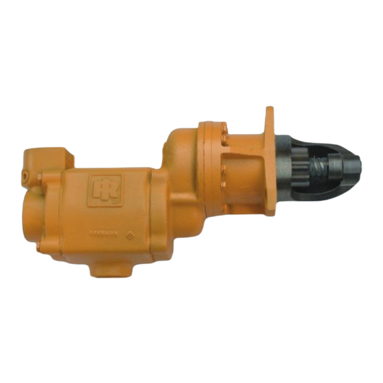
Summary of Contents for Ingersoll-Rand 150BMGE
- Page 1 P6031 03524832 Edition 13 January 2014 Air and Gas Powered Starter Series 150BMG Installation and Maintenance Information Save These Instructions...
-
Page 2: Model Coding
Product Safety Information Intended Use: The 150BMG Series Air starters are intended for use in starting reciprocating internal combustion engines. These starters are designed to be operated from a remote location after proper installation on the engine requiring starting. For Additional information refer to Air Starters Product Safety Information Manual Form 45558624. - Page 3 If either of these conditions in cold weather. If either of these conditions Ingersoll-Rand recommends that the Relay Valve be mounted on the exist, the starter will not operate. After all connections have been air tank.
- Page 4 40 psig (2.8 bar/280 kPa) and immerse the unit for Ingersoll-Rand No. MBA31 Plastic Gasket, as directed, and the 30 seconds in light oil, or non-flammable solvent. If there are following procedures for assembly and testing must be explicitly any bubbles, the unit is unfit for gas operation.
- Page 5 150BMG Series Air and Gas Starters Dimensional Drawing 03524832_ed13...
- Page 6 150BMG Series Air and Gas Starters Typical Installation PIPING DIAGRAM FOR A BASIC INERTIA TYPE SYSTEM STARTER CONTROL VALVE SMB-G618 #4 HOSE (1/4”) AIR PRESSURE GAUGE CHECK VALVE 150BMP-1064L 150BMP-1056 JIC 37˚ ADAPTER 1/4 NPT JIC 37˚ ADAPTER 1 1/2 NPT...
- Page 7 150BMG Series Air and Gas Starters Sectional View (Dwg. TPA61-7) 03524832_ed13...
- Page 8 150BMG Series Air and Gas Starters - Exploded View (Dwg. TPA683-2) 03524832_ed13...
-
Page 9: Part Description
150BMG Series Air and Gas Starters - Parts List Part Item Part Description Item Part Description Part Number Number Motor Housing Cover Assembly 150BMP-A102A Drive Shaft Housing Cover End Plug (3) HSPPS3 for Model E22RH5-020 10BM-108 Nameplate 150BM-301 for Models C21RH-6, C21LH-11,... -
Page 10: Maintenance Section
Maintenance Section WARNING Always wear eye protection when operating or performing any maintenance on this Starter. Always turn off the air or Gas supply and disconnect the air supply hose before installing, removing or adjusting any accessory on this Starter or before performing any maintenance on this Starter. Note: When reading the instructions, refer to exploded diagrams in parts Information Section when applicable. - Page 11 Inspection of Parts 3. Check all needle bearings. Discard any needle bearing that was pressed from a parent member during disassembly of the starter. 1. Discard all O-rings and gaskets. These should not be reused. Remove and discard any other needle bearing that appears worn, 2.
-
Page 12: Testing The Starter
12. Set the Front End Plate (39), crescent grooved side first, onto the 4. Wipe a thin film Ingersoll Rand No. 130 Grease on the Drive Cylinder so that the Cylinder Dowel passes through the dowel Gear Thrust Washer (19A), and place the Washer on the lip of the hole in the End Plate. -
Page 13: Troubleshooting Guide
Troubleshooting Guide Trouble Probable Cause Solution No air supply Check for blockage or damage to air supply lines or tank. Damaged motor assembly Inspect Motor Assembly and power train and repair or replace if necessary. Foreign material in motor and/or piping Remove Motor Assembly and/or piping and remove blockage. - Page 14 Notes:...
- Page 15 Notes:...
- Page 16 ingersollrandproducts.com © 2014 Ingersoll Rand...


Need help?
Do you have a question about the 150BMGE and is the answer not in the manual?
Questions and answers