Table of Contents
Advertisement
Quick Links
Before installing or starting this unit for the first time,
this manual should be studied carefully to obtain a
working knowledge of the unit and/or the duties to be
performed while operating and maintaining the unit.
RETAIN THIS MANUAL WITH UNIT. This Technical
manual contains IMPORTANT SAFETY DATA and
should be kept with the unit at all times
More Than Air. Answers.
Online answers:
http://www.air.irco.com
Ingersoll Rand
System Automation X4I
Operator's Manual
C.C.N. : 80443617
REV.
: A
DATE
: APRIL 2007
Advertisement
Table of Contents

Subscribe to Our Youtube Channel
Related Manuals for Ingersoll-Rand X4I


Summary of Contents for Ingersoll-Rand X4I
- Page 1 Ingersoll Rand System Automation X4I Operator’s Manual Before installing or starting this unit for the first time, this manual should be studied carefully to obtain a working knowledge of the unit and/or the duties to be performed while operating and maintaining the unit.
-
Page 2: Table Of Contents
AUXILIARY OUTPUT (OPTION) ........ 16 SECTION 9 — SYSTEM CONFIGURATION ...... 29 RS485 COMMUNICATIONS ........16 ACCESSING THE X4I CONFIGURATION SCREENS ..29 SECTION 6 — CONTROL FEATURES AND FUNCTIONS ... 17 USER CONFIGURATION: TAB S01 ......29 STANDARD CONTROL FEATURES AND FUNCTIONALITY... 17 REAL TIME CLOCK SETTINGS ......... -
Page 3: Table Of Contents
DIGITAL (SWITCHING) INPUT EXCEPTIONS....58 PRE-FILL CONFIGURATION P02 TAB SCREEN ..46 SECTION 11 — FAULT CODES ........59 PRE-FILL FUNCTION SETTINGS ......47 X4I COMPRESSOR FAULT INDICATIONS, TYPES, AND CODES.. 59 PRE-FILL TIME SETTINGS ........47 ALARM (WARNING)..........59 PRE-FILL PRESSURE SETTINGS........ 48 NOT AVAILABLE ........... -
Page 4: Section 2 — Introduction
The X4I is completely customizable to meet the air system. The X4I is capable of controlling up to four specific needs of your compressed air system. positive displacement air compressors. The compressors... -
Page 5: Section 3 — Safety
W A R N IN G : R is k o f H ig h P re s s u re devices, guards or insulation materials fitted to the X4I. The X4I must only be operated at the • W A R N IN G : C o n s u lt M a n u a l supply voltage and frequency for which it is designed. - Page 6 “WORK IN PROGRESS - DO NOT APPLY VOLTAGE”. Do not switch The X4I must only be cleaned with a damp • on electrical power or attempt to cloth, using mild detergents if necessary.
-
Page 7: Section 4 — Compressor Connection And Control
The factory default settings for the pressure sensor is 0– grounded conduit. 232 PSI (16 bar), but the X4I can accept any pressure sensor Each air compressor must be equipped with an online/ with a 4–20 mA output and a range of up to 8700 PSI (600 offline pressure regulation system capable of accepting a bar). -
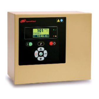
Page 8: X4I Main Display
ON – Active, Running Unit Fault Indicator (Red LED) Fast Flash: Shutdown (Trip) Slow Flash – Alarm (Warning) The keypad and navigation keys on the X4I are depicted below and provide the following functionality. Keypad and Navigational Keys Functionality Start... -
Page 9: Section 5 — Installation
It is recommended that installation and commissioning be carried out by an authorized and trained product supplier. The X4I can be mounted on a wall using conventional bolts. The X4I can be located remotely from the compressors as long as it is within 330 feet (100 meters) of cable length. -
Page 10: Power Supply
DEMAND (DRY) SIDE PRESSURE CONTROL A fused switching isolator must be installed to the main incoming power supply, external to the X4I. The isolator must be fitted with a properly sized fuse to provide adequate protection to the power supply cable used (in accordance with local electrical and safety regulations). -
Page 11: Pressure Sensor Connection
ALARM For each compressor utilizing an IR-PCB, connection to the X4I the signal wires must be made to the correct X4I terminals for that compressor number. Compressor 1 should be wired to terminal X01 on the terminal PCB,... -
Page 12: Input Functions
In instances where a convenient voltage signal for a Consult the X4I Interconnect and Application Guide compressor ready condition is not available, the “ready” prior to the installation of the X4I and the IR-PCB to the air input can be connected directly to a constant compressor compressor. -
Page 13: Run Input
A U X IL IA R Y S W IT C H warning lamp, or warning circuit, will energize. The IR-PCB will detect the voltage and signal the X4I that a warning has occurred. If the compressor has no accessible warning circuit, or this function is not required, the IR-PCB alarm terminals can be ignored. -
Page 14: Output Functions
When connected, the pressure switch can be switched in and out of circuit automatically. If the X4I is stopped or This terminal provides volt free contact closure, referenced experiences a failure or loss of power, pressure control will... -
Page 15: Service Maintenance Switch
X4I is stopped or experiences a fault or loss of power. SERVICE MAINTENANCE SWITCH + V D C + V D C... -
Page 16: Auxiliary Output (Option)
To avoid this possibility, always The X4I is equipped with a remote relay contact output at use shielded cables, securely bonded to a known ground at terminals 33 and 34 (X08). -
Page 17: Section 6 — Control Features And Functions
This cycle will repeat as long as the X4I is able to keep the system air pressure between PH and PL. -
Page 18: Damping
When system pressure is in the tolerance band, the X4I will system. Tolerance (TO) and damping (DA) can be used continuously calculate the moment at which compressors for minor tuning of the system. will be loaded or unloaded based on the rate of change of system pressure. -
Page 19: Standard Control Features And Functionality
V = [.25 x (2.6 x 1)]/.34 FIRST IN LAST OUT ROTATION MODE (FILO) V = (.25 x 2.6)/.34 The default configuration of the X4I provides FILO (First In/ Last Out) sequence control strategy. V = .65/.34 V = 1.91 m... -
Page 20: Sequence Rotation Events
1 and the other three compressors a priority of 2, the The primary function of VEC mode is to accommodate variable speed compressor will always remain at the front of a variable speed compressor connected to the X4I using an the sequence: IRV-PCB interface. -
Page 21: Tables And The Pressure Schedule
See the Quick Setup Manual. Two independently rotating compressor groups If the X4I is able to complete the transition in less time than is allotted without threatening energy efficiency then PC will be automatically shortened. -
Page 22: Pre-Fill
At system start (manual start or automated start from hours is assigned as the third trim compressor. For systems standby), the X4I will only load compressors that have been with more than two compressors, the compressors will be pre-set for pre-fill operation, for a pre-set period of time. -
Page 23: First In First Out Mode (Fifo)
If system pressure continues to decrease, compressor 2 (B) The running hours meter display on most compressors will be loaded and be reassigned to (A) while compressor 1 are intended for approximate service interval indication is reassigned as (D). If this causes system pressure to rise only and may deviate in accuracy over a period of time. -
Page 24: Section 7 — Display And Menu Operation
SECTION 7 — DISPLAY AND MENU OPERATION The Main Display and the keypad and navigation buttons on the X4I are depicted below and provide the following functionality: User Interface The User Interface display functiuonality is depicted below: User Interface DisplayUser Interface... - Page 25 Stopped Standby Started and Running Real Time Clock 24 Hour Format Compressor Status: The following Icons are used by the X4I to display the Compressor/s Status. Stopped Service Maintenance Active Standby (or Auto Restart) Alarm (Warning) Running Offload Not Available (Stopped, Shutdown, Trip)
-
Page 26: Display Item Structure
DISPLAY ITEM STRUCTURE INFORMATION DISPLAYS Operational system status and values are accessible from To view detailed information applicable to the selected User the normal user display. To view status or values that are not normally visible on the default screen, press UP or menu display item press the ENTER button: DOWN. -
Page 27: Operational Functions
OPERATIONAL FUNCTIONS If the power failure auto-restart function is enabled, the X4I will automatically start when power is restored after a disruption or failure, if the X4I was in a “started” state when the power disruption or failure occurred. STOP To stop the X4I, press STOP. -
Page 28: Section 8 — Commissioning
Before successful basic operation can be established specific parameters must be entered prior to startup. See the section on Installation for more Please refer to the X4I Quick Setup Manual for instruction to information. accomplish this. -
Page 29: Section 9 — System Configuration
When in menu mode, you must press the escape User Configuration Home Screen button until you are returned to the Main menu. If you do not, the X4I remains in the menu mode After successfully entering the access code you should see the screen shown below. -
Page 30: Real Time Clock Settings
The flashing cursor should This parameter enables or disables the Pressure be displayed highlighting the Minutes dash. This Schedule Function in the X4I. sets the Minutes for the Real Time Clock. The values for this parameter are “0” to “59”. -
Page 31: Auto Restart Settings
Auto Restart is turned on. When enabled, determined day and time each week. after a power disruption or failure, the X4I will automatically restart when power is restored if the X4I was in an operational ‘Started’ state when the... -
Page 32: Table Select Settings
TABLE SELECT SETTINGS Scroll up (+) or scroll down (-) until the value is set for the Rotation Interval From the S01 home screen scroll up (+) required for your air system. Press the ENTER scroll down (-) to move the cursor to button to accept this parameter. -
Page 33: Backlight Adjust Settings
Units Settings 2. The default setting for this parameter is PSI. The PSI indicates the pressure units selected for X4I. This parameter determines the X4I display and operating units. 3. Press the ENTER button to display the Units configuration screen. -
Page 34: Number Of Compressors Settings
If PH in Table 1 (T01) is set for will be sequenced by the X4I. This value must be 100 PSI, and PH in Table 2 (T02) set to match the system at commissioning. -
Page 35: Stop Control Settings
04- CF (Stop Control Function Settings). Tolerance Settings The default setting for this parameter is 3.0 PSI. This is the width of the Tolerance Band for the X4I. The Tolerance Band setting is a pressure band above and below the Load and Unload pressure band. -
Page 36: Damping Settings
The default setting for this parameter is 4 Min. The necessary once the initial compressor is running, 4 minutes is the time the X4I will use implement a loaded, and able to contribute adequate additional smooth and controlled change from one ‘target’... -
Page 37: Auxiliary Output Settings
With this setting, the function for the Auxiliary “01:T1”Override > Use Table 1 • Output for X4I is set to the X4I is Active. The “02:T2”Override > Use Table 2 • function of the Auxiliary Output as well as the state of the contacts controlling the Auxiliary Output can “03:T3”Override >... -
Page 38: Error Log Reset
6. You should be returned to the S02 home screen event of a X4I shutdown or loss of power and the should appear next to the ER parameter. -
Page 39: Pressure Sensor – Offset
PRESSURE SENSOR – OFFSET PRESSURE SENSOR – RANGE SETTINGS From the S03 home screen scroll up (+) From the S03 home screen scroll up (+) scroll down (-) to move the cursor to scroll down (-) to move the cursor to highlight 01- 1O (Pressure Sensor 1 Offset highlight 02- 1R (Pressure Sensor Range Settings). -
Page 40: Compressor Configuration: Tab C01
This value can be manually set to match the running hours of each compressor. When using the C02 Tab Screen EHR (Equal Run Hours) Sequence mode, the X4I uses these values to maintain equal run hours among all compressors. 2. Press the ENTER button to confirm your selection. -
Page 41: Compressor Connection Method
X4I. Each air 11. IRV-PCB Setup: Scroll up (+) or scroll compressor in the system is integrated with the X4I using an interface module. down (-) to change the value to IRV-PCB. -
Page 42: Compressor Table Configuration: Tab T01
0V=! for an Alarm (Warning) condition is 24. The flashing cursor should be displayed • generated if the ‘ir-PCB’ Alarm input highlighting the Compressor Start Sequence Time. detects no voltage. The Default setting for this parameter is 10 Sec. This is the time required to start the motor and then load the compressor. -
Page 43: High Pressure Setpoint Settings
Press the ENTER button to confirm your Scroll up (+) or scroll down (-) selection. The cursor should be flashing on line 01 until the number is set to the value required to maintain control of for your air system. Press the ENTER button to confirm your selection. -
Page 44: Minimum Pressure Alarm Settings
You should be returned to the T01 home screen and values just entered should appear next to the PL parameter. 80 PSI FILO ( MINIMUM PRESSURE ALARM SETTINGS From the T01 home screen scroll up (+) scroll down (-) to move the cursor to highlight 03- Pm (Minimum Pressure Alarm). -
Page 45: Compressor #2 Through 4 Priority Settings
COMPRESSOR #2 THROUGH 4 PRIORITY SETTINGS Repeat Steps above for Compressor #2, #3, and #4 FILO ( Priority settings. When complete, the ENTER button to confirm your selection. You should be returned to the T01 home screen After you have completed adjusting the settings on Compressor #1 Priority Setting the T01 screen, press the ESCAPE button to... -
Page 46: Pressure Schedule Settings
Schedule is turned off. The Pressure Schedule consists of 28 individual settings that instruct the X4I to change from one Table to another, or put the 11. Scroll up (+) or scroll down (-) system into Standby mode, dependant on time of until the value is set for the Pressure Schedule day and day of the week. -
Page 47: Pre-Fill Function Settings
“ ” for Pre-fill, Standard Mode • Press ENTER to confirm your selection. The cursor should be flashing on line 01 PF. ii. If one or more of the pre-defined pre-fill compressors experiences a shutdown, or is stopped, the pre-fill function is cancelled and normal operation begins. -
Page 48: Pre-Fill Pressure Settings
The default setting for this parameter is 0 PS. The 0 PSI indicates the Pressure Setpoint used by the X4I to determine if the Pre-fill Function is required Press the ENTER button to display the Pre-fill at startup. If the system pressure is at, or above, Time Setpoint screen. -
Page 49: Diagnostics D01 Tab Screen
A3Analog Input 3v 20 Ao 4.00 ____________________________________________________ 01 D1 AoAnalog Output0.0 to 20.0mA Diagnostic Setting Screen The X4I is equipped with comprehensive diagnostic functions. Each input can be examined individually and each output can be manually activated or manipulated individually. -
Page 50: Digital Inputs
Analog inputs 2 and 3 are equipped with ACM modules designed to conform to the standard specification for a controller digital input. The inputs are utilized as digital inputs on this X4I. ANALOG OUTPUT The analog output can be manually adjusted. Use UP (plus) and DOWN (Minus) to adjust and ENTER. - Page 51 The Default Parameters for all X4I settings are shown in the following lists. TABLE #1 TABLE #3 Pulsing PHHigh Pressure Setpoint Default Setting is: 102 PSI PHHigh Pressure Setpoint PLLow Pressure Setpoint Default Setting is: 102 PSI Default Setting is: 98 PSI...
- Page 52 Pre-fill Configuration PFPre-fill Function P>Pressure Units Default Setting is: X Default Setting is: PSI PTPre-fill Time NCNumber Of Compressors Default Setting is: - MIN Default Setting is: 4 PPPre-fill Pressure PMMaximum Pressure Alarm Default Setting is: 0 PSI Default Setting is: 145 PSI 01Compressor #1 CFStop Control Function Default Setting is: X...
- Page 53 Compressor Running Hours 01Compressor #1 Running Hours Default Setting is: 0 HRS 02Compressor #2 Running Hours Default Setting is: 0 HRS 03Compressor #3 Running Hours Default Setting is: 0 HRS 04Compressor #4 Running Hours Default Setting is: 0 HRS Compressor Configuration 01Compressor #1 Configuration Default Setting is: IR-PCB 02Compressor #2 Configuration...
-
Page 54: Ir-Pcb (Ingersoll Rand Compressor Interface Pcb)
X03-3 (GND) is 0Vac and 0VDC common. GND is also The ‘ir-PCB’ provides 3kV opto-coupled isolation between connected to ‘earth’ on the X4I Terminal PCB (this is not a compressor circuit pressure regulation and monitoring ‘Safety Earth’ connection and is used for “control” only). -
Page 55: Ir-Pcb' Pressure Regulation Control Inputs
G N D V F D 24Vac When the X4I is set up for in VFD mode (IRV-PCB), the controller will send a signal to the VFD input (V) on the ir- C 0 3 PCB. Its associated diagnostic LED 5 will be on indicating... -
Page 56: Status Signals
Se rv ic e M a int e na nc e In addition, if the ‘D1’ wire connection from the X4I to the When the Alarm or Service Maintenance signals are present ‘ir-PCB’ is not connected the ‘D2’ output on the ‘ir-PCB’ pin on C04 or C05, they can be monitored on connection C03 terminal 5 (D1). -
Page 57: Functions
DETERMINING TERMINAL PCB TO CONTROLLER I/O CONNECTIONS FROM THE X4I WIRING DIAGRAM FOR USE WITH THE CONTROLLER DIAGNOSTIC TEST FUNCTIONS Example: ‘ir-PCB 1’ Ready/Run Signal to Controller Di2 (Digital Input 2) Terminal C015 C019 C016 C020 C017 C021 C018 +20VDC... -
Page 58: Digital (Switching) Input Exceptions
DIGITAL (SWITCHING) INPUT EXCEPTIONS ‘ir-PCB’ #4: The ‘Alarm/Service Note: A digital (switching) conditioning circuit is not • Maintenance’ digital input (X04-22) is employed on analog input 2 (‘ir-PCB’ #4 Alarm/Service monitored by a DC voltage ‘Analogue’ Maintenance) because this input has a ‘pulsing’ state that input (A2) on the unit’s controller. -
Page 59: Section 11 — Fault Codes
Insufficient Capacity COMPRESSOR INHIBITED, REMOVED FROM SERVICE Set in the X4I active “table” (# = table number 1, 2 or 3) as Compressor fault states are displayed as part of the inhibited from use. normal operational status display and do not generate fault codes. -
Page 60: Special Controller Fault Codes
The error code • Error code symbols (if applicable) • The date the error occurred • The time the error occurred • The active operational functions of the X4I • at the time the error occurred; (see: X4I Status Display for Icons) -
Page 61: Parts List
PARTS LIST Item Part No. Description 39265889 80443617 Manual, User CD 39265897 Unit, Controller 39265913 Unit, XPM-TAC24 39265905 PCB, Terminal 38036703 Gland, Set - Pg11 39265921 Module, ir-PCB 39265939 Sensor, Pressure 4-20mA, 232psi (16bar) i-PCB 20mm Qty. Part No. Description 39265962 IEC Fuse T1.0A 39265970... -
Page 62: Technical Data
TECHNICAL DATA Mounting Dimensions: Dimensions (HxWxD) 9.45” x 11.45” x 6.0” 24mm 238mm 241mm x 291mm x 152mm 24mm Weight 14 lb (6.4 kg) Mounting Wall, 4 x mounting screws Enclosure IP65, NEMA 4 Power Supply 50VA 188mm 236mm 230Vac +/- 10% (50 Hz) 115Vac +/- 10% (60 Hz) Control Power 24Vdc... -
Page 63: Diagrams
DIAGRAMS Wiring Diagram T 1-5 6-32 1 -R 6 -C G T erm in al P C B C 0 1 C 0 3 C 0 4 C 0 3 + V D C A i1 C 0 4 C 0 5 C 0 5 C 0 6 + V D C... - Page 64 Connection Diagram Terminal PCB 115V 'UL ' @ 5A maximum. Auxiliary Output #1 Auxiliary Input #1 330ft (100m) max Multi485 330ft (100m) max System + Ai1 Pressure 4- 20mA +20VDC ir-PCB4 Ready/Run Alarm/Serv. 330ft (100m) max LOAD IR- PCB 6 - core IRV- PCB 7 -core +20VDC ir-PCB3...
- Page 65 XPM-TAC24 Power Supply Module 12 mm 4 x 4.5mm BLACK BLUE BROWN ORANGE WHITE GREEN VIOLET VOLTAGE SELECT 230V +-10% 230V 115V 115V +-10% T1.0A 5x20mm 12 mm 24Vac/1 24Vac/2 L N E earthed isolated...
- Page 66 X4I Commissioning Form Customer Contact Customer Ref: Phone Internal Ref: Installation/Site Commission Date Ser No. Commission Engineer Software Comp #1 Manufacturer Comp #1 Model/Type Comp #1 Working Pressure psi/bar VA Hz Comp #1 Full Load Capacity Comp #2 Manufacturer Comp #2 Model/Type...
- Page 67 Real Time Clock Set Pressure Schedule Enable Auto Restart Enable Rotation Interval or Time Default Table P> Pressure Units Number of Compressors Maximum Pressure Alarm psi/bar Stop Control Function Tolerance Damping Pressure Change Time Auxiliary Input Function Auxiliary Output Function Pressure Offset Pressure Range Prefill Function...
- Page 68 Machine models represented in this manual may be used in various locations world-wide. Machines sold and shipped into European Union Territories require that the machine display the EC Mark and conform to various directives. In such cases, the design specification of this machine has been certified as complying with EC directives.
Need help?
Do you have a question about the X4I and is the answer not in the manual?
Questions and answers