
Related Manuals for Ingersoll-Rand SS815 Series


Summary of Contents for Ingersoll-Rand SS815 Series
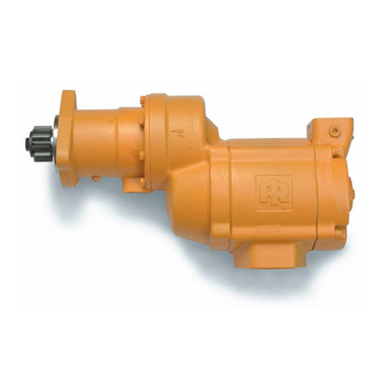
- Page 1 P6567 03531480 Edition 13 January 2014 Starters Series SS815, SS825 and SS850 Installation and Maintenance Information Installation and Maintenance Information 安装和维护信息 据付および保守の情報 Save These Instructions...
-
Page 2: Installation
Product Safety Information Intended Use: These air starters are intended for use in starting reciprocating internal combustion engines. These starters are designed to be operated from a remote location after proper installation on the engine requiring starting. For additional information refer to Air Starters for Internal Combustion Engines Product Safety Information Manual Form 45558624. Manuals can be downloaded from ingersollrandproducts.com. - Page 3 Orientation of the Air Starter 4. Using a 1-1/2” short nipple, install the SRV150 Starter Relay Valve on the end of the receiver tank as shown in Dwg. TPC444-4 on EN-7. If the factory orientation will not fit your engine due to radial location 5.
- Page 4 Barring Over the Engine The HDL2 Lubricator is self-priming and may be installed directly on the Starter or located remotely. Although the Lubricator is capable Occasionally, for setting injectors and/or for timing purposes, it may of drawing lubricant from a source 4 ft (1.2 m) lower than the point be desirable to bar over the engine in such a manner that any given of installation, Ingersoll Rand recommends installing the Lubricator piston can be stopped at any given location.
- Page 5 Mounting Dimensions for Series SS815 and SS825 Starters (Dwg. TPA1325-1) 03531480_ed13...
- Page 6 Mounting Dimensions for Series SS850 Starters (Dwg. TPA832-5) 03531480_ed13...
- Page 7 Typical Vehicular Installation (Shown with SS815 Starter) Starter Control Valve #4 Hose SMB-618 (Brass) Air Pressure Guage Air Supply To Relay from Compressor #4 Hose Valve From Starter JIC 37º SRV125-1242 Control Valve Check Valve "IN" Port JIC 37º JIC 37º Adapter Adapter 1/4"...
- Page 8 Typical Installation with Engine Prelube System #4 Hose Starter Control Valve SMB-618 Oil Pressure Sensing Valve Exhaust #4 Hose "OUT" Port JIC 37° Adapter 1/4" N.P.T. Air Pressure "IN" Port JIC 37° Gage Adapter 1/4" N.P.T. #4 Hose For natural gas operation, starter main exhaust must be piped away.
- Page 9 Typical Multiple Starter Installation #4 Hose #4 Hose JIC 37º Adapter "OUT" Port JIC 37º 1-1/4" N.P.T. Starter Control Valve Adapter 1/4" N.P.T. "IN" Port JIC 37º SMB-618 Adapter 1/4" N.P.T. 1-1/2" Pipe 1-1/2" Hose #4 Hose JIC 37º Adapter 1-1/2"...
- Page 10 产品安全信息 用途: 此类空气启动器应用于往复式内燃机的启动。此类启动器应在正确安装到需要启动的内燃机上后,进行远程操作。 更多信息请参见内燃机空气启动器产品安全信息手册表 45558624。 手册可从 ingersollrandproducts.com 下载。 使启动器处于使用状态 注 意 对于天然气操作,必须用管道排出起动器的主排气管。 要用管道连接传动箱处排气口,先卸下传动箱阀塞,然后用适当的管线替代。管线必须在安全的位置排气,并且不得与任何其他排气管 线互连,这些管线可能会对传动箱阀产生回压。 润滑 正确润滑对达到起动器的最高性能和最大耐用性非常重要。 装。使用优质的 10W 非中性清洁剂机油来润滑。调整润滑器以使 其每秒涌出 1 至 3 滴。 建议的两种润滑系统: 小 心 Ingersoll Rand No.HDL2 润滑器: 要安装盘车时间期低于 10 秒 的起动器。请按图 TPB978 进行安装。(请参见 EN-4 上 HDL2 滑 在使用...
- Page 11 16. 如果排气装置无法排气,可在起动器的马达外壳的排气管端口 注 意 中安装 No. SS660-A674 消声器或 No. SM450-A735 公路防溅导 向板。 确保已将 SRV150 起动器主 启动阀和气罐连接到继动阀进口侧 17. 如果装有起动器的发动机没有外壳(配有标准起动器装置), (在阀座上标注为字母“IN”) 。 以及为该装置制造的托架,我们建议您在起动器的电动机尾部 4. 使用 1-1/2” 的短螺纹接套将 SRV150 起动器主 启动阀安装在 增加其他支架。为此,马达外壳盖中有 4 个孔。它们是分接的 气罐末端,如图 TPC444-4(EN-6 上)所示。 M10-1.50 以符合米制有头螺丝。 5. 请在仪表板上(车载装置)或某些其他相应面板上(固定装 18. 将 HDL2 润滑器安装在起动器上或起动器附近,如图 置)安装...
- Page 12 SS815 和 SS825 系列起动器的安装尺寸 (图. TPA1325-1) 03531480_ed13...
- Page 13 SS850 系列起动器的安装尺寸 (图. TPA832-5) 03531480_ed13...
- Page 14 典型的车载安装(通过 SS815 起动器显示) #4�号软管 起动器控制阀�SMB-618(铜) 压力表 来自压缩机的气源 进至主启动阀 #4�号软管 �始于起动器控制阀 JIC 37º SRV125-1242 检查阀门 37º�接头� 37º� “进口”端�JIC 1 - 1/2" N.P.T. �接头�1/4" N.P.T. 37º� “出口”端�JIC �接头�� 1/4" N.P.T. -1/2"�软管 1 - 1/2" N.P.T. 空气储气罐 润滑系统供应管线 空气�气动起动器 PTF� 管道塞子�1/8"-27 150-1-1/2"� SAE�套筒传动 1-1/2"�管道...
- Page 15 具有发动机预先润滑系统的典型安装 #4�号软管 起动器控制阀�SMB-618 油压感应阀 排气装置 37º� #4�号软管 “出口”端�JIC �接头�1/4" N.P.T. “进口”端�JIC 37º� 气压计 �接头�1/4" N.P.T. #4�号软管 37º�接头� 对于天然气操作,必须用管道排出起动器的主排气管 1 -1/2" N.P.T. 要用管道连接传动箱阀,先卸下传动箱阀塞,然后用 1-1/2"�主启动阀� 适当的管线替代��管线必须在安全的位置排气,并且 不得与任何其他排气管线互连,这些管线可能会对传 SRV150 动箱控制气口处产生回压 1-1/2"�管道 JIC 37º 接头� 要预先润滑泵 1/4" N.P.T. 1-1/2"�管道 检查阀� 150BMP-1054 储气罐��最大压力不超 1-1/2" 管道 过起动器商标上显示的...
- Page 16 典型多起动器安装 #4�号软管 #4�号软管 “出口”端� “进口”端�JIC 37º� JIC 37º 接头� �JIC 37º�接头 �接头�1/4" N.P.T. 起动器控制阀� 1 -1/4" N.P.T. �1/4" N.P.T. SMB-618 1-1/2"�管道 1 -1/2"�软管 #4�号软管 JIC 37º�接头� 1 -1/2" N.P.T. 润滑器�NL-24-8 1-1/2"�主启动阀� #4�号软管 SRV150 管道排气装置或使用消声器� #4�号软管 SS660-A674�或导向板� SM450-A375 “出口”端� 1-1/2"�管道 JIC 37º�接头� “进口”端�JIC 37º�...
- Page 17 製品に関する安全性 製品に関する安全性 これらのエアスターターは、 往復内燃機関の始動に使用するこ とを目的と しています。 これらのエアスターターは、 始動させる必要のある往復内 燃機関に正しく 取り付けた後、 離れた場所から操作するように設計されています。 詳細は、 「 内燃機関用エアスターター製品安全情報説明書 45558624」 を参照してく ださい。 irools.com から説明書をダウンロードすることができます。 始動装置の供用 天然ガス運転をする場合、 始動装置のメイン排気は、 配管で排出する必要があります。 駆動部筐体排出口に配管するために、 駆動部筐体栓を外して適切な管類ラインに取り換えます。 管類は、 安全な位置で排気する必要があり、 駆動部筐体の排出口に逆圧の発生を招く おそれのある他の排気ラインとの相互接続をしないようにする必要があります。 潤滑 適切な lubrication は、 始動装置の、 最高の性能および最大の耐久 Ingersoll Rand No. NL-24-8 インライン ルブリケータ。 性を得るのに必須です。...
- Page 18 12. リング ギアに良好な粘着性のある、 ギア グリースまたはオート バイのチェーン用潤滑油を十分に塗ります。 こ うすると、 リング 方向変更時または再組付け時に [モーター筐体] を [モーター筐体カ ギアおよび始動装置のピニオンの寿命を延ばすのに役立ちま バー] から分離させないでく ださい。 す。 13. [始動装置] を所定の位置に移動し、 フライホイール ベル筐体上 3. ここで、 [駆動部筐体] は、 [変速装置] に対して正しい方向にする に取り付けます。 取り付けボルトを100 ft-lb (136 Nm) のトルクま ことができたので、 排気ポートが底にあるかないか、 および吸気 で締め付けます。 口が、 ホースの再組付けに対し、 好ましい位置に配置されている 14. [始動装置制御バルブ] の ” DEL “ 側から [始動装置駆動筐体] 上 かに注意します。 これらの構成部品の片方または両方の方向を の ” IN “ ポートに1/4 インチ #4 ホース ラインを再組付けしす。 変える必要がある場合、...
- Page 19 HDL2 ルブリケータの再組付け 空気供給ホース 潤滑油供給ホース 潤滑油供給ホース 始動装置空気供給室または油室 遠隔 HDL2 ルブリケータの再組付け (図面. TPB978) HDL2 ルブリケータを以下のように取り付けます。 HDL2 の側面の 1/8” インチ NPTF 注油口から圧力の加わらない 燃料ライン、 ディーゼル燃料タンクまたは別の油容器に 1/4 イ HDL2 ルブリケータを [始動装置] 上に取り付けようとする場合、 ンチホースを再組付けします。 ルブリケータの取り付け金具を [始動装置] の吸入口の突起から 3/8 インチパイプ栓の内の1つ 15 ~ 36 ft-lb (20.3 ~ 40.8 Nm) のトルクで締め付けます。 取り付 を外してHDL2と取り替えます。 HDL2 を離れた位置に取り付ける け金具上のネジは清浄にする必要があり、 シーリング材または 場合、 ルブリケータ用に使用できる 2本のU ボルトおよび基礎取 Teflon®* テープを使用せずに取り付け金具を組み立てます。 接 付金具を使用します。 続は、 真空気密にする必要があります。 HDL2 を離れた位置に取り付けた場合、 雄ネジ、 雌ネジの両方 を有するルブリケータの末端から [始動装置] 吸入口の突起上...
- Page 20 SS815 および SS825 シリーズ始動装置の取り付け寸法 (図面. TPA1325-1) 03531480_ed13...
- Page 21 SS850 シリーズ始動装置の取り付け寸法 (図面. TPA832-5) 03531480_ed13...
- Page 22 典型的な車両再組付け (SS815 始動装置で表示) 始動装置制御バルブ #4 ホース SMB-618 (真ちゅう 風圧計 コンプレッサーからの空気供給 リレーバルブへ #4 ホース 始動装置制御 JIC 37º SRV125-1242 バルブから チェック バルブ 37º アダプタ “IN” ポート JIC 37º 1/2 インチ N.P.T. アダプタ 1/4 インチ N.P.T. “OUT” ポート JIC 37º アダプタ-1/4 インチ N.P.T. -1/2 インチ ホース 1 - 1/2" N.P.T. 空気だめタンク 注油供給ライン 空気/ガス始動装置 パイプ栓 1/8 インチ - 27 PTF SRV 150-1-1/2 SAE ソケッ...
- Page 23 エンジン潤滑前システムの典型的再組付け #4 ホース 始動装置制御バルブ SMB-618 油圧検出バルブ 排気管 “OUT” ポート JIC 37º #4 ホース アダプタ1/4 インチ “IN” ポート JIC 風圧計 37º N.P.T. アダプタ 1/4“インチ N.P.T. #4 ホース 天然ガス運転をする場合、 始動装置のメイン排気は、 配 。 JIC 37º アダプタ 管で排出する必要があります 1 -1/2” インチ N.P.T. [駆動部筐体通気孔] に配管するために、 [駆動部筐体栓] SRV150 1-1/2 を外して適切な管類ラインに取り換えます。 管類は、 安全 インチ リレー バルブ な位置で排気する必要があり、 [駆動部筐体] に逆圧の発 生を招くおそれのある他の排気管との相互接続をしない 1-1/2 インチ パイプ JIC 37º アダプタ 潤滑前ポンプへ 。...
- Page 24 典型的な複式始動装置の再組付け #4 ホース #4 ホース “OUT” ポート 37º アダプタ アダプタ JIC 37º “IN” ポート 始動装置制御バルブ -1/4 インチ N.P.T. 1/4 インチ N.P.T. アダプタ JIC 37º SMB-618 1/4 インチN.P.T. 1-1/2 インチ パイプ 1 -1/2 インチ ホース #4 ホース 37º アダプタ 1 -1/2 インチ N.P.T. ルブリケータ NL-24-8 SRV150 1-1/2 イン ガスの場合、 排気は配管で排 #4 ホース チ リレー バルブ 出されるかまたはマフラー SS660-A674 または偏向器 #4 ホース SM450-A375 を使用します。 1-1/2 インチ パイプ “OUT” ポート 37º アダプタ “IN” ポート...
- Page 25 Front End Construction of Series SS850 (Dwg. TPA853-4) 03531480_ed13...
- Page 26 Series SS815 and SS825 Starters Exploded Diagram (Dwg. TPA778-6) 03531480_ed13...
- Page 27 Series SS815 and SS825 Starters Parts List Item Part Description Part Number Item Part Description Part Number Motor Housing Drive Housing Cap Screw (8) SS800-744 with 2-1/2” Tapped Exhaust Drive Housing Cap Screw SS800-40 CE210-605 with 2-1/2” SAEJ518C Lock Washer (8) SS800-140 Flanged Exhaust Drive Housing Kit...
- Page 28 Series SS850 Starters Exploded Diagram (Dwg. TPA820-3) 03531480_ed13...
- Page 29 Series SS850 Starters Parts List Item Part Description Part Number Item Part Description Part Number Motor Housing Drive Housing Cap Screw (8) SS800-744 with 2-1/2” Tapped Exhaust Drive Housing Cap Screw SS800-40 CE210-605 with 2-1/2” SAEJ518C Lock Washer (8) SS800-140 Flanged Exhaust Drive Housing Kit SS850-K300...
-
Page 30: Drive Housing
Maintenance, Disassembly / Assembly Instructions WARNING Always wear eye protection when operating or performing any maintenance on this starter. Always turn off the air supply and disconnect the air supply hose before installing, removing or adjusting any accessory on this starter or before performing any maintenance on this starter. -
Page 31: Motor Housing
Motor Housing Remove the Large Rear Rotor Bearing O-Ring (11). Remove the Rear End Plate (9) from the rotor shaft. Unscrew and remove the Motor Housing Cover Cap Screw (4). Remove the Small Rear Rotor Bearing O-Ring (10A) from the rotor Pull the Motor Housing Cover (2) from the motor Housing (1). - Page 32 22. Align the punch marks on the Gear Case (58), Motor Housing (1) 16. Slide the Piston Return Spring (56) onto the Drive Shaft and snap and Motor Housing Cover (2) and assemble as follows: it into the front of the Piston so that it is against the Large Drive Grasp the Gear Case (58) in a vise by the Drive Gear Shaft.
-
Page 33: Troubleshooting Guide
Troubleshooting Guide Trouble Probable Cause Solution Check for blockage or damage to air supply lines or tank. No air supply. Inspect Motor Assembly and power train and repair or replace if Damaged Motor Assembly necessary. Motor will not run Foreign material in Motor and/or piping Remove Motor Assembly and/or piping and remove blockage. - Page 34 Notes:...
- Page 35 Notes:...
- Page 36 ingersollrandproducts.com © 2014 Ingersoll Rand...
Need help?
Do you have a question about the SS815 Series and is the answer not in the manual?
Questions and answers