Sign In
Upload
Download
Table of Contents
Contents
Add to my manuals
Delete from my manuals
Share
URL of this page:
HTML Link:
Bookmark this page
Add
Manual will be automatically added to "My Manuals"
Print this page
×
Bookmark added
×
Added to my manuals
Manuals
Brands
Rohde & Schwarz Manuals
Measuring Instruments
NGU-K104
User manual
Rohde & Schwarz NGU-K104 User Manual
Source measure units
Hide thumbs
Also See for NGU-K104
:
User manual
(218 pages)
1
2
3
4
5
6
7
8
9
10
11
12
13
14
15
16
17
18
19
20
21
22
23
24
25
26
27
28
29
30
31
32
33
34
35
36
37
38
39
40
41
42
43
44
45
46
47
48
49
50
51
52
53
54
55
56
57
58
59
60
61
62
63
64
65
66
67
68
69
70
71
72
73
74
75
76
77
78
79
80
81
82
83
84
85
86
87
88
89
90
91
92
93
94
95
96
97
98
99
100
101
102
103
104
105
106
107
108
109
110
111
112
113
114
115
116
117
118
119
120
121
122
123
124
125
126
127
128
129
130
131
132
133
134
135
136
137
138
139
140
141
142
143
144
145
146
147
148
149
150
151
152
153
154
155
156
157
158
159
160
161
162
163
164
165
166
167
168
169
170
171
172
173
174
175
176
177
178
179
180
181
182
183
184
185
186
187
188
189
190
191
192
193
194
195
196
197
198
199
200
page
of
200
Go
/
200
Contents
Table of Contents
Bookmarks
Table of Contents
Table of Contents
Outp:gen
Table of Contents
Safety
Intended Operation
Unpacking and Checking the Instrument
Setting up the Instrument
1 Documentation Overview
Data Sheet
Manuals
Release Notes, Open Source Acknowledgment
2 Welcome to R&S NGU
Ambient Conditions
3 Important Notes
Symbols
Mains Voltage
Measurement Categories
Limits
4 Getting Started
Putting into Operation
Bench Operation
Front Panel
Rack Mounting
Instrument Tour
Overview of Controls
Rear Panel
Switching on the Instrument
Trying out the Instrument
Activating the Channel Output
Setting the Output Voltage and Current
Maintenance
Maintenance and Support
Contacting Customer Support
Status Bar Information
Channel Display Area
Using Gestures
Using the Touchscreen
Accessing Functionality in the Home Window
5 Operating Basics
Display Overview
Settings Button
Voltage and Current Inputs
Input Data
Front Panel Keys
Menu Controls
Home Key
Settings Key
User Key
Navigation Controls
Output and Channel Controls
Power Derating
Operation Modes
Voltage and Current Priority Modes
Set Constant Resistance
Fast Transient Response
Output
6 Instrument Functions
Setting the Channels Voltage and Current
Activating the Channel Output
Impedance
Delay
Trigger Events
Output Mode
Current Priority Mode
High Capacitance Mode
Ranges / Digital Voltmeter (DVM)
Modulation Input
Battery Simulator
Overcurrent Protection (OCP)
Protection
Overpower Protection (OPP)
Overvoltage Protection (OVP)
Safety Limits
Trigger / Digital I/O
Advanced Features
Arbitrary
Ramp
User Key
Screenshot
Data Logging
Fastlog
CSV Settings
Graphical View Window
File Manager
Store and Recall
Interfaces
Network Connection
LAN Connection
USB Connection
GPIB Address
General Instrument Settings
Licenses Management
Appearance Settings
Sound Settings
Date and Time
Device Information
Update Device
Device Documentation
Common Setting Commands
System Settings Commands
Display Commands
Trigger Commands
Configuration Commands
Safety Limit Setting
Voltage Setting
Current Setting
Resistance Setting
Combined Setting of Voltage and Current Setting
Output Setting
7 Remote Control Commands
Parameters
Output:general[:State]
Output:delay:duration 1
Output[:State]
Output:delay[:State]
Output:ftresponse 1
Output:impedance
Output:impedance:state
Output:mode
Output:select
Output:triggered
Output:triggered[:State]
Output:triggered:behavior
Range/DVM Setting
Modulation Input
Source Priority Mode Setting
OCP Setting
Power Line Cycle Setting
OVP Setting
OPP Setting
USB Class Setting
Measurement Commands
Parameters
Measure[:Scalar]:Current[:DC]
Measure[:Scalar]:Current[:DC]:Avg
Measure[:Scalar]:Current[:DC]:Max
Measure[:Scalar]:Current[:DC]:Min
Measure[:Scalar]:Current[:DC]:Statistic
Measure[:Scalar]:Power
Measure[:Scalar]:Power:avg
Measure[:Scalar]:Power:max
Measure[:Scalar]:Power:min
Measure[:Scalar]:Power:statistic
Measure[:Scalar][:Voltage][:DC]
Measure[:Scalar][:Voltage][:DC]:Avg
Measure[:Scalar][:Voltage][:DC]:Max
Advanced Operating Commands
Measure:voltage:DVM
Measure[:Scalar][:Voltage][:DC]:Min
Measure[:Scalar][:Voltage][:DC]:Statistic
Arbitrary
Ramp
Digital I/O
Battery Simulation
Battery:simulator:capacity
Battery:simulator:capacity:limit
Battery:simulator:current
Battery:simulator:current:limit
Battery:simulator:current:limit:eoc
Battery:simulator:current:limit:eod
Battery:simulator:current:limit:regular
Battery:simulator:resistance
Battery:simulator:soc
Battery:simulator:tvoltage
Battery:simulator:voc
Battery:simulator:voc:empty
Battery:model:current:limit:eoc
Battery:simulator:voc:full
Battery:simulator[:Enable]
Battery:status
Battery:model:capacity
Battery:model:clear
Battery:model:current:limit:eod
Battery:model:current:limit:regular
Battery:model:data
Battery:model:fname
Battery:model:isoc
Battery:model:load
Data and File Management Commands
Battery:model:save
Battery:model:transfer
Parameters
Data:data
Data:delete
Data:list
Data:points
Flog:data
Flog:file:duration
Flog:srate
Flog:triggered
Flog:file:tpartition
Flog:target
Flog[:State]
Hcopy:data
Hcopy:size:X
Hcopy:size:y
Log:count
Log[:State]
Log:duration
Log:fname
Log:interval
Log:mode
Log:stime
Log:triggered
Status Reporting Commands
Status:operation Registers
Status:questionable Registers
A Additional Basics on Remote Control
Annex
Messages
Messages and Command Structure
SCPI Command Structure
Command Sequence and Synchronization
Preventing Overlapping Execution
Status Reporting System
Structure of a SCPI Status Register
List of Commands
Index
Advertisement
Quick Links
Download this manual
www.allice.de
R&S
Source Measure Units
User Manual
(;ÝIO2)
1179253102
Version 02
®
NGU
Allice Messtechnik GmbH
Table of
Contents
Previous
Page
Next
Page
1
2
3
4
5
Advertisement
Chapters
Table of Contents
6
Parameters
125
Parameters
147
Battery Simulation
162
Parameters
170
Table of Contents
Need help?
Do you have a question about the NGU-K104 and is the answer not in the manual?
Ask a question
Questions and answers
Related Manuals for Rohde & Schwarz NGU-K104
Measuring Instruments Rohde & Schwarz R&S NGU201 User Manual
Source measure units (218 pages)
Measuring Instruments Rohde & Schwarz NRP2 User Manual
Power meter (419 pages)
Measuring Instruments Rohde & Schwarz NRX Getting Started
Power meter (28 pages)
Measuring Instruments Rohde & Schwarz NRX User Manual
Power meter (530 pages)
Measuring Instruments Rohde & Schwarz R&S NRX User Manual
Power meter (522 pages)
Measuring Instruments Rohde & Schwarz NGU201 User Manual
Source measure units (200 pages)
Measuring Instruments Rohde & Schwarz NGU Getting Started
Source measure units (28 pages)
Measuring Instruments Rohde & Schwarz NRP-Z00 Getting Started
Power sensors (40 pages)
Measuring Instruments Rohde & Schwarz NRT2 User Manual
Power reflection meter (206 pages)
Measuring Instruments Rohde & Schwarz NRT 1080.9506.02/.62 Operating Manual
Power reflection meter (194 pages)
Measuring Instruments Rohde & Schwarz NRPM OTA Power Measurement Solution Manual
(229 pages)
Measuring Instruments Rohde & Schwarz NRVD Operating Manual
Power meter (166 pages)
Measuring Instruments Rohde & Schwarz NPA Getting Started
Power analyzers (57 pages)
Measuring Instruments Rohde & Schwarz R&S NPA Series User Manual
Power analyzers (269 pages)
Measuring Instruments Rohde & Schwarz R&S NRP Operating Manual
Power meter (350 pages)
Measuring Instruments Rohde & Schwarz HM8118 User Manual
Programmable lcr-bridge (76 pages)
Summarization of Contents
Documentation Overview
1.1 Manuals
Locates documents for the R&S NGU product, including user and service manuals.
1.2 Data Sheet
Contains technical specifications, options, and order numbers for R&S NGU source measure units.
Important Notes
3.2 Ambient Conditions
Specifies allowed operating temperature, humidity, and ventilation requirements for the instrument.
3.5 Limits
Lists the instrument's protection limits for voltage, current, and power to ensure safe operation.
Getting Started
4.1 Putting into Operation
Details the initial setup process for R&S NGU source measure units, including safety.
4.2 Instrument Tour
Provides an overview of the R&S NGU controls and steps for initial power-on.
4.3 Trying Out the Instrument
Guides users through basic instrument functions like setting voltage and activating output.
4.4 Maintenance and Support
Covers basic instrument maintenance procedures and how to contact customer support.
Operating Basics
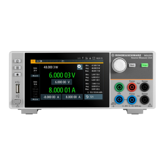
5.1 Display Overview
Explains the instrument's home window layout, including output status and control settings.
5.2 Using the Touchscreen
Details touchscreen gestures and methods for accessing instrument functions.
5.3 Front Panel Keys
Describes the functions of the instrument's front panel keys for navigation and control.
5.5 Operation Modes
Explains the different operating modes like CV, CC, CR, and priority modes of the R&S NGU.
Instrument Functions
6.1 Setting the Channels Voltage and Current
Details how to set the voltage and current values for the instrument's output channels.
6.2 Activating the Channel Output
Explains how to switch the instrument's output channels on and off.
6.8 Protection
Covers instrument protection features like OCP, OVP, OPP, and safety limits.
6.10 Advanced Features
Describes advanced functions such as Arbitrary waveform generation and Ramp functions.
6.19 Interfaces
Details how to configure network, USB, and GPIB interfaces for remote control.
6.20 General Instrument Settings
Covers settings for appearance, sound, date/time, and device information.
Remote Control Commands
7.1 Common Setting Commands
Lists and explains common SCPI commands for instrument control and status.
7.5 Configuration Commands
Details SCPI commands for configuring instrument settings like voltage and current.
7.6 Measurement Commands
Provides SCPI commands for querying measurement values like voltage, current, and power.
7.7 Advanced Operating Commands
Explains SCPI commands for advanced functions like Arbitrary and Battery Simulation.
7.9 Status Reporting Commands
Describes SCPI commands for querying instrument status and error information.
Annex
A.1 Messages and Command Structure
Explains instrument message types and the structure of SCPI commands.
A.3 Status Reporting System
Details the structure and description of SCPI status registers.
Table of Contents
Print
Rename the bookmark
Delete bookmark?
Delete from my manuals?
Login
Sign In
OR
Sign in with Facebook
Sign in with Google
Upload manual
Upload from disk
Upload from URL
Need help?
Do you have a question about the NGU-K104 and is the answer not in the manual?
Questions and answers