Table of Contents
Advertisement
Quick Links
Advertisement
Table of Contents

Related Manuals for Rohde & Schwarz NRX


Summary of Contents for Rohde & Schwarz NRX
- Page 1 ® R&S Power Meter User Manual (;ÜÅÐ2) 1178556602 Version 09...
- Page 2 ® This manual describes the R&S NRX (1424.7005K02) with firmware version FW 02.50 and later. In addition to the base unit, the following options are described: ● ® R&S NRX-B1 (1424.7805K02) ● ® R&S NRX-B4 (1424.8901K02) ● ® R&S NRX-B8 (1424.8301K02) ●...
-
Page 3: Table Of Contents
® Contents R&S Contents 1 Safety and regulatory information............11 Safety Instructions...................... 11 Labels on the product....................13 Warning messages in the documentation..............14 Korea certification class B..................14 2 Welcome....................15 Documentation overview....................15 2.1.1 Getting started manual....................15 2.1.2 User manual........................15 2.1.3 Instrument security procedures..................15 2.1.4 Printed safety instructions..................... - Page 4 ® Contents R&S Manual operation......................33 4.1.1 Start dialog........................33 4.1.2 Main measurement dialog.....................34 4.1.3 Status information......................36 4.1.4 Notification center......................37 4.1.5 Selecting the display layout...................38 4.1.6 Swapping measurement panes..................40 4.1.7 Editing parameters......................41 4.1.8 Creating and saving screenshots..................42 4.1.9 Restricting manual operation..................
- Page 5 ® Contents R&S 6.4.1 Trace result display....................... 76 6.4.2 Trace settings........................77 6.4.3 Trace Marker dialog...................... 78 Pulse analysis......................81 6.5.1 Pulse analysis result display..................82 6.5.2 Pulse analysis settings....................82 6.5.3 Pulse Analysis dialog....................83 Time gate........................90 6.6.1 Time gate result display....................91 6.6.2 Time gate settings......................
- Page 6 ® Contents R&S 7.5.3 NRT filter settings......................132 8 Saving and recalling settings............134 9 Zeroing sensors................. 136 10 System settings..................138 10.1 Connections......................138 10.1.1 Network settings......................139 10.1.2 Remote settings......................142 10.1.3 Input/output settings (I/O)....................145 10.1.4 Sensor manager......................151 10.2 Instrument info......................154 10.2.1 System info.........................
- Page 7 ® Contents R&S 13.3 Addressing measurements and power sensors............ 187 13.4 Making measurements..................... 188 13.4.1 Using MEASure?......................188 13.4.2 Using CONFigure and READ?..................189 13.4.3 Using CONFigure, INITiate and FETCH?..............190 13.4.4 Configuring one setting at a time................190 13.4.5 Structure of combining commands................191 13.5 Starting and ending a measurement...............
- Page 8 ® Contents R&S 13.8.8 NRT measurement type....................366 13.9 Configuring the test generator................376 13.10 Configuring the analog signal ouput and the trigger input/output...... 378 13.11 Zeroing........................387 13.12 Running selftests...................... 389 13.13 Managing setups and correction tables..............392 13.14 System information and configuration..............
- Page 9 ® Contents R&S 14.2.2 Syntax for device-specific commands.................469 14.2.3 SCPI parameters......................470 14.2.4 Overview of syntax elements..................473 14.2.5 Structure of a command line..................473 14.2.6 Responses to queries....................474 14.3 Command sequence and synchronization............. 475 14.3.1 Preventing overlapping execution................475 14.4 Status reporting system...................
- Page 10 ® Contents R&S User Manual 1178.5566.02 ─ 09...
-
Page 11: Safety And Regulatory Information
Intended use Combined with the supported R&S power sensors, the R&S NRX base unit is intended for power measurements in development and production. The supported R&S power sensors are listed in the data sheet. Observe the operating conditions and perfor- mance limits stated in the data sheet. - Page 12 ® Safety and regulatory information R&S Safety Instructions Never open the casing of the product. Only service personnel authorized by Rohde & Schwarz are allowed to repair the product. If any part of the product is dam- aged or broken, stop using the product. Contact Rohde & Schwarz customer service at http://www.customersupport.rohde-schwarz.com.
-
Page 13: Labels On The Product
® Safety and regulatory information R&S Labels on the product ● Only use the power cable delivered with the product. It complies with country-spe- cific safety requirements. Only insert the plug into an outlet with protective conduc- tor terminal. ● Only use intact cables and route them carefully so that they cannot be damaged. -
Page 14: Warning Messages In The Documentation
® Safety and regulatory information R&S Korea certification class B Table 1-1: Labels regarding environment safety Labeling in line with EN 50419 for disposal of electrical and electronic equipment after the prod- uct has come to the end of its service life. For more information, see "Disposing electrical and electronic equipment"... -
Page 15: Welcome
R&S NRX product page at: www.rohde-schwarz.com/manual/NRX 2.1.1 Getting started manual Introduces the R&S NRX and describes how to set up and start working with the prod- uct. A printed version is delivered with the instrument. 2.1.2 User manual Contains the description of all instrument modes and functions. -
Page 16: Release Notes And Open Source Acknowledgment (Osa)
The release notes list new features, improvements and known issues of the current firmware version. The open source acknowledgment and the license texts of open source software pack- ages used in the R&S NRX software are provided under: [System] > "Instrument Info" > "Help & Copyrights" For further details, see Chapter 10.2.4, "Help &... -
Page 17: Getting Started
3.1.1 Lifting and carrying "Lifting and carrying the product" on page 12. The R&S NRX weighs below 3 kg, details are provided in the data sheet. Due to the low weight, you can move the R&S NRX easily. 3.1.2 Unpacking and checking 1. -
Page 18: Setting Up The Product
3.1.4.1 Placing the product on a bench top The R&S NRX is a small and lightweight product. You can stack the R&S NRX with other products, but place the R&S NRX on top. In the following procedure, the weight indication for stacking refers to the most common design of larger Rohde & Schwarz instruments. - Page 19 ® Getting started R&S Preparing for use – 25 kg when stacking smaller products on top (middle figure). Left = Stacked correctly, same dimensions Middle = Stacked correctly, different dimensions Right = Stacked incorrectly, too many products 4. NOTICE! Overheating can damage the product. Prevent overheating as follows: ●...
-
Page 20: Considerations For Test Setup
Use a conductive floor mat and heel strap combination. 3.1.6 Connecting to power The R&S NRX can be used with different AC power voltages and adapts itself auto- matically to them. Adjusting the R&S NRX to a particular AC supply voltage is therefore not required. -
Page 21: Connecting To Lan
5 = Sensor connector of the R&S NRX 6 = R&S NRX Use an R&S NRP‑ZK8 cable to connect an R&S power sensor to the R&S NRX. If you use an R&S NRP‑ZK6 cable, the reference clock and trigger are not supported. - Page 22 R&S power sensor. Note: Incorrectly connecting/disconnecting an R&S power sensor can damage the power sensor or lead to erroneous results. 3.1.8.2 Optional interface for R&S NRT-Z sensors (R&S NRX-B9) Chapter 3.2.1.2, "Module bay", on page 26.
-
Page 23: Connecting Usb And External Devices
3. Connect the host interface connector of the R&S NRT‑Zxx directional power sensor (6) to the interface for R&S NRT-Z sensors (R&S NRX-B9). To disconnect the R&S NRT‑Zxx directional power sensor 1. -
Page 24: Switching On Or Off
® Getting started R&S Preparing for use 3.1.10 Switching on or off Table 3-1: Overview of power states Status Position of power switch Standby orange Ready green To switch on the product The product is off but connected to power. 1. -
Page 25: Instrument Tour
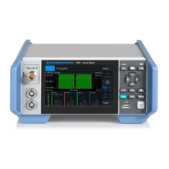
Front panel tour.......................25 ● Rear panel tour....................... 29 3.2.1 Front panel tour Figure 3-3: Front panel of the R&S NRX = Module bay for optional connectors, see Chapter 3.2.1.2, "Module bay", on page 26. = Sensor connectors A and B, see Chapter 3.2.1.1, "Sensor connectors A and... - Page 26 If no option is installed, the module bay is closed by a cover. Sensor check source (R&S NRX-B1) Used as a power reference for testing the connected power sensors and the cabling. The LED of the sensor check source (R&S NRX-B1) shows the state, see Table 3-2.
- Page 27 See (3) in Figure 3-3. The R&S NRX displays results in panes. Depending on the measurement mode, val- ues are displayed digitally or graphically. False triggers can occur If an object (e.g. a human finger) that is charged with static electricity is brought near the touch panel, false triggers can occur.
- Page 28 134. If you press [Preset] again, the preset function starts. "Preset" on page 135. If you press the [Preset] key during booting, the R&S NRX starts with the factory default state. [Zero] Pressing [Zero] opens the "Zeroing Sensors" dialog.
-
Page 29: Rear Panel Tour
Further information: ● Chapter 3.2.2.5, "AC supply and power switch", on page 30 ● Chapter 3.1.10, "Switching on or off", on page 24 3.2.2 Rear panel tour Figure 3-4: Rear panel of the R&S NRX User Manual 1178.5566.02 ─ 09... - Page 30 "I/O 1, I/O 2 tabs" on page 147 3.2.2.2 Ethernet interface See (2) in Figure 3-4. The Ethernet connector is an RJ45 socket for remote controlling the R&S NRX via a network. 3.2.2.3 USB device interface See (3) in Figure 3-4.
- Page 31 R&S Instrument tour When the R&S NRX is connected to the AC supply, it automatically sets itself to the correct range for the applied voltage. The range is printed on the casing. There is no need to set the voltage manually.
- Page 32 ® Getting started R&S Instrument tour For the R&S NRX with the name plate shown in Figure 3-5, the default hostname is: NRX-100758 Further information: ● "System Info" on page 155 ● "Host Name" on page 140 3.2.2.8 Sensor connectors C and D...
-
Page 33: Operating Concepts
● Remote control......................44 4.1 Manual operation Using the graphical user interface of the R&S NRX and the keys on the front panel, you can easily configure the settings and measure in the provided measurement modes. Using the touchscreen A touchscreen allows you to interact with the software using various finger gestures on the screen. -
Page 34: Main Measurement Dialog
® Operating concepts R&S Manual operation Figure 4-1: Start dialog (example for setup with one power sensor) 1 = Measurement pane 2 = Connected sensors 3 = Miniature display layout. See Chapter 4.1.5, "Selecting the display layout", on page 38. 4 = Title 5 = Measurement type 6 = Status information. - Page 35 ® Operating concepts R&S Manual operation Layout of the main measurement dialog The operating philosophy in the main measurement dialog is independent of the mea- surement type. The dialog is divided into touch areas that lead to different settings. Figure 4-2: Layout of the main measurement dialog (example) 1 = Measurement value displayed in the measurement pane 2 = Settings displayed in the measurement pane 3 = Limit values displayed in the measurement pane...
-
Page 36: Status Information
23 Memory stick is connected and initialization is in pro- gress. When the moving green dot vanishes, the memory stick is ready for use. R&S NRX is in remote control. Chapter 4.3.2, "Returning to manual operation (LOCAL)", on page 45... -
Page 37: Notification Center
R&S NRX is in remote control. Manual operation is disabled. Identification and initialization of a connected power sensor is in progress. 4.1.4 Notification center The notification center collects all information during the operation of the R&S NRX: ● Notices ● Warning messages ●... -
Page 38: Selecting The Display Layout
® Operating concepts R&S Manual operation The "Notification Center" dialog has two tabs: ● "System" All messages concerning the instrument are listed. ● "SCPI Error Queue" Messages related to the remote command functionality are displayed. To delete notices no longer needed ►... - Page 39 ® Operating concepts R&S Manual operation 3. Select how many measurement panes you want to display. For example, if you select 2 panes, the measurement display looks as follows: Figure 4-3: Two measurement panes Remote command: on page 201 DISPlay:LAYout on page 203 DISPlay[:WINDow<Window>][:STATe] User Manual 1178.5566.02 ─...
-
Page 40: Swapping Measurement Panes
® Operating concepts R&S Manual operation 4.1.6 Swapping measurement panes You can swap the position of measurement panes using drag and drop. The numbering of the panes is not changed. To change the position of a measurement pane ► Touch & hold a measurement pane and drag it into the new position. The two panes have changed position: In the "Select Display Layout"... -
Page 41: Editing Parameters
® Operating concepts R&S Manual operation Remote command: on page 203 DISPlay[:WINDow<Window>]:POSition 4.1.7 Editing parameters 1. Tap a parameter to change its value. Depending on the selected parameter, a numeric or an alphanumeric editor is dis- played. 2. Tap to display the value range of the parameter ("Min", "Max"). 3. -
Page 42: Creating And Saving Screenshots
29 4.1.9 Restricting manual operation For security measures, you can restrict the manual operation allowed at the R&S NRX. 1. Select [System] > "Instrument Info" > "Security". 2. On the "General" tab, select "User Interface". The "User Interface" dialog contains settings to restrict access in various degrees. -
Page 43: Remote Operation
R&S NRX simultaneously. By default, VNC access is enabled. Any user in the network who knows the password and IP address of the R&S NRX can access the R&S NRX. To prevent access, disable the VNC server service under "VNC"... -
Page 44: Remote Control
Ctrl + E [Zero] Ctrl + N 4.3 Remote control The R&S NRX is equipped with various interfaces for connecting it to a controller for remote control: ● IEC/IEEE bus interface (standard equipment) in line with the standards IEC 60625.1 (IEEE 488.1) and IEC 60625.2 (IEEE 488.2) ●... -
Page 45: Returning To Manual Operation (Local)
4.3.2 Returning to manual operation (LOCAL) If the R&S NRX is in remote control, you can display settings using the front-panel keys and the touchscreen, but you cannot change settings. To do that, you have to return to manual operation. -
Page 46: Measurement Basics
151. 5.2 Sensor assignment and memory When you connect an R&S power sensor to the R&S NRX, the R&S NRX tries to rec- ognize the sensor. The sensor recognition is based on the sensor type and the serial number of the power sensor. - Page 47 2. Perform a trace measurement. 3. Remove the R&S NRQ6 and connect it to port B. The R&S NRX recognizes the sensor type and assigns the R&S NRQ6 to the same measurement. Example: Using two sensors of the same type 1.
-
Page 48: Performing A Measurement
R&S Performing a measurement The sensor assignment is deleted by a preset, reset or sanitization. If the R&S NRX has no memory of a previous sensor assignment, the R&S NRX assigns the measure- ments according to the port, to which the power sensors are connected. The number of measurement panes is adapted automatically. -
Page 49: Limit Violation
® Measurement basics R&S Limit violation a) Press the [Preset] key. b) Tap "Preset". See also Chapter 8, "Saving and recalling settings", on page 134. 2. Depending on the power sensor and the measurement conditions, consider to zero the power sensor: Execute zeroing: Note: Turn off all measurement signals before zeroing. -
Page 50: Settings Conflict
® Measurement basics R&S Settings conflict 5.5 Settings conflict A settings conflict can occur for the following reasons: ● The sensor assigned to the measurement does not support a set value. If it is a numeric value, the suitable range for the sensor is given in the tooltip. ●... - Page 51 ® Measurement basics R&S Settings conflict 2. Select another measurement type that the sensor supports, or assign another sen- sor. A setting that differs from the preset value is also indicated across the hierarchies by a pencil symbol, if the visualization is enabled. See "Visualize Non-Preset State"...
-
Page 52: Measurement And Display Configuration
® Measurement and display configuration R&S Configuration for all measurement types 6 Measurement and display configuration The different measurement types and their specific configuration settings are described in the following. Settings available for all measurements are described in Chapter 6.1, "Configuration for all measurement types", on page 52. - Page 53 ® Measurement and display configuration R&S Configuration for all measurement types Figure 6-1: Display dialog, example for time gate measurement Resolution........................54 Unit..........................54 Forward Unit........................54 Display Format......................54 Auxiliary Values......................55 Scaling.......................... 55 └ Scale Lower Limit....................55 └ Scale Upper Limit....................56 └...
-
Page 54: Resolution
® Measurement and display configuration R&S Configuration for all measurement types └ Forward Lower Limit, Reflection Lower Limit..........61 └ Forward Upper Limit State, Reflection Upper Limit State....... 61 └ Forward Upper Limit, Reflection Upper Limit..........61 Resolution Configures the resolution of the measurement. For logarithmic power values (dB, dBm or dBμV), the number of decimal places is set directly. -
Page 55: Auxiliary Values
® Measurement and display configuration R&S Configuration for all measurement types "Scalar Analog" Numeric format with bar chart "Graphical" Available for time gate, timeslot measurements. Measured values are plotted over time. Remote command: on page 198 CALCulate<Measurement>:DMODe Auxiliary Values Available for the graphic displays of continuous average, burst average measure- ments. -
Page 56: Scale Upper Limit
® Measurement and display configuration R&S Configuration for all measurement types Scale Upper Limit ← Scaling Display Format is set to "Scalar Analog", available for continuous average, burst average, time gate, timeslot measurements. Defines the upper limit of the bargraph display. Remote command: CALCulate<Measurement>:METer<DirectionalChannel>:UPPer[:DATA]: on page 208... -
Page 57: Start Time
® Measurement and display configuration R&S Configuration for all measurement types CALCulate<Measurement>:METer<DirectionalChannel>:UPPer[:DATA]: RATio:RFRatio CALCulate<Measurement>:METer<DirectionalChannel>:UPPer[:DATA]: RATio:RLOSs CALCulate<Measurement>:METer<DirectionalChannel>:UPPer[:DATA]: RATio:SWR CALCulate<Measurement>:METer<DirectionalChannel>:UPPer[:DATA]: RATio[:VALue] CALCulate<Measurement>:METer<DirectionalChannel>:UPPer[:DATA][: POWer] Start Time ← Scaling Available for trace, pulse analysis measurements. If Display Format is set to "Graphi- cal", available for time gate, timeslot measurements. Defines the position of the left screen edge relative to the delayed trigger. -
Page 58: Power Span
® Measurement and display configuration R&S Configuration for all measurement types Sets the vertical scaling. The power per division is one tenth of the Power Span. The combination of Power Reference and this parameter define the vertical orientation of the trace. Remote command: on page 216 [SENSe<Sensor>:]TRACe:TIME... -
Page 59: Max Hold
Remote command: CALCulate<Measurement>:HOLD[:STATe] Max Hold Function For all measurement functions, the R&S NRX stores the maximum and minimum val- ues and the calculated differences between these values. The selected setting applies to both power and reflection indication. You can change at any time. -
Page 60: Upper Limit State
® Measurement and display configuration R&S Configuration for all measurement types Remote command: CALCulate<Measurement>:LIMit<DirectionalChannel>:LOWer[:DATA] CALCulate<Measurement>:LIMit<DirectionalChannel>:LOWer[:DATA]: POWer CALCulate<Measurement>:LIMit<DirectionalChannel>:LOWer[:DATA]: RATio:RCOefficient CALCulate<Measurement>:LIMit<DirectionalChannel>:LOWer[:DATA]: RATio:RFRatio CALCulate<Measurement>:LIMit<DirectionalChannel>:LOWer[:DATA]: RATio:RLOSs CALCulate<Measurement>:LIMit<DirectionalChannel>:LOWer[:DATA]: RATio:SWR CALCulate<Measurement>:LIMit<DirectionalChannel>:LOWer[:DATA]: RATio[:VALue] Upper Limit State ← Limit Monitor Available for continuous average, burst average, time gate, timeslot measurements. Enables or disables the monitoring function for the upper limit. - Page 61 ® Measurement and display configuration R&S Configuration for all measurement types Forward Lower Limit, Reflection Lower Limit ← Limit Monitor Available for NRT measurements. Defines a lower limit. Remote command: CALCulate<Measurement>:LIMit<DirectionalChannel>:LOWer[:DATA] on page 221 CALCulate<Measurement>:LIMit<DirectionalChannel>:LOWer[:DATA]: CCDF CALCulate<Measurement>:LIMit<DirectionalChannel>:LOWer[:DATA]: POWer CALCulate<Measurement>:LIMit<DirectionalChannel>:LOWer[:DATA]: RATio:RCOefficient CALCulate<Measurement>:LIMit<DirectionalChannel>:LOWer[:DATA]: RATio:RFRatio CALCulate<Measurement>:LIMit<DirectionalChannel>:LOWer[:DATA]:...
-
Page 62: Controlling The Measurement
6.1.2.1 Controlling the measurement results The R&S NRX can cope with the wide range of measurement scenarios with the help of the so-called "termination control". Depending on how fast your measurement results change, you can define, how the measurement results are output. -
Page 63: Triggering
® Measurement and display configuration R&S Configuration for all measurement types 6.1.3 Triggering In a basic continuous measurement, the measurement is started immediately after the initiate command. However, sometimes you want that the measurement starts only if a specific condition is fulfilled. For example, if a signal level is exceeded, or in certain time intervals. - Page 64 "Sensor Check Requires the sensor check source (R&S NRX-B1) *TRG Source" option. TRIGger<Measurement>[:IMMediate] If enabled, the sensor check source (R&S NRX- B1) sends trigger signals using the internal trigger bus. See "Sensor Check Source tab" on page 146. "Bus (*TRG)"...
- Page 65 ® Measurement and display configuration R&S Configuration for all measurement types If you use a hold-off time instead of a dropout time, you can obtain stable triggering conditions - regular triggering at the same point. But you cannot achieve exclusive trig- gering at A.
-
Page 66: Trigger Mode
® Measurement and display configuration R&S Configuration for all measurement types Trigger Mode Controls the trigger execution depending on the settings under "Trigger Source" on page 66. "Normal" Continuous triggering with regular trigger events. "Freerun" Enables a continuous measurement. The power sensor executes one measurement cycle after the other. -
Page 67: Specific Trigger
® Measurement and display configuration R&S Configuration for all measurement types Remote command: TRIGger<undef>:ALL:SLOPe TRIGger<Measurement>[:CHANnel<Channel>]:SLOPe Level ← Trigger Advanced "Trigger Level" on page 66- Delay ← Trigger Advanced Sets the delay between the trigger event and the beginning of the actual measurement. Remote command: TRIGger<undef>:ALL:DELay[:VALue] TRIGger<Measurement>[:CHANnel<Channel>]:DELay[:VALue]... -
Page 68: Trigger Sender State
"Internal [A to D]", where [A to D] is the port to which the trigger sender is connected. The trigger signal generated by the trigger sender is routed to the R&S NRX and from there it is distributed to the trigger receivers and, if Trigger Source for Trigger Output is set to "Sensor [A to D]", also to the trigger output. -
Page 69: Measurement Settings Dialog
® Measurement and display configuration R&S Configuration for all measurement types 6.1.4 Measurement settings dialog Access: In the main measurement dialog, tap the displayed measurement value or graphic. See also "Layout of the main measurement dialog" on page 35. In this dialog, you select the measurement type and the channel calculation function. Based on the selected measurement and function, you can assign one or two sensors. -
Page 70: Primary Sensor, Secondary Sensor
Assigns the primary or secondary sensor. You can choose any of the sensors that are connected to a sensor port of the R&S NRX. The port letter, to which the sensor is con- nected, is displayed in front of the hostname of the sensor. -
Page 71: Quick Setup
Specifies whether the display settings are kept unchanged when tapping Recall Parameter Set. Configures the power sensor and the display settings of the R&S NRX. See Chapter 13.8.6.3, "Display configuration", on page 363. Only configures the power sensor. User Manual 1178.5566.02 ─ 09... -
Page 72: Continuous Average
® Measurement and display configuration R&S Continuous average Remote command: on page 352 SYSTem:STANdard:PWSettings Recall Parameter Set ← Quick Setup Loads the parameters set selected under Parameter Set. Remote command: on page 351 SYSTem:STANdard:PRESet 6.2 Continuous average The power sensor measures the signal average power asynchronously within a defined time interval, the so-called aperture or sampling window. -
Page 73: Continuous Average Settings
® Measurement and display configuration R&S Continuous average 6.2.2 Continuous average settings Access: "Measurement Settings" > "Measurement Type" > "Continuous Average" Unit..........................73 Resolution........................73 Display.......................... 73 Rel..........................73 └ Reference Value..................... 73 └ Relative Measurements.................. 74 Trigger........................... 74 Unit "Unit" on page 54. Resolution "Resolution"... -
Page 74: Burst Average
® Measurement and display configuration R&S Burst average Relative Measurements ← Rel Allows you to relate measured power or a power ratio to a reference value. Whether the power is measured by one power sensor or whether it is a combined value mea- sured by two power sensors, is set by "Channel Calculation Function"... -
Page 75: Burst Average Result Display
® Measurement and display configuration R&S Burst average interval in which the pulse end is only recognized if the signal level no longer exceeds the trigger level. Useful parameters: ● "Trigger Level" on page 66 ● "Dropout" on page 67 ●... -
Page 76: Trace
® Measurement and display configuration R&S Trace Display Chapter 6.1.1, "Display settings", on page 52. "Rel" on page 73. Trigger Chapter 6.1.3, "Triggering", on page 63. 6.4 Trace The power sensor measures power over time. Define the number of measurement points and the measurement time. -
Page 77: Trace Settings
® Measurement and display configuration R&S Trace 6.4.2 Trace settings Access: "Measurement Settings" > "Measurement Type" > "Trace" Display.......................... 77 Pos / Scaling......................... 77 Autoscale........................77 Info / Marker........................77 M1 / M2 / M3 / M4......................77 Trigger........................... 78 └... -
Page 78: Trace Marker Dialog
® Measurement and display configuration R&S Trace Trigger Gives quick access to selected trigger settings. Shows the trace. The trigger level is indicated as dotted red line. Display ← Trigger Chapter 6.1.1, "Display settings", on page 52. Trig Mode ← Trigger "Trigger Mode"... - Page 79 ® Measurement and display configuration R&S Trace Marker Mode......................... 79 Position Mode....................... 79 Position......................... 80 Data Source........................81 Reference Marker......................81 Measurement Mode...................... 81 Marker Mode Enables or disables the marker. Also defines the appearance of the marker. "Off" Disables the marker. "Ruler"...
- Page 80 ® Measurement and display configuration R&S Trace "From Ref Power <-" Starting from the right border, at a power difference of Position to the y-position of the Reference Marker. "From Ref Power ->" Starting from the left border, at a power difference of Position to the y- position of the...
-
Page 81: Pulse Analysis
® Measurement and display configuration R&S Pulse analysis Data Source Available if "Measure" is set under Marker Mode. Selects the trace. Remote command: DISPlay[:WINDow<Window>]:TRACe:MARKer<Marker>:FEED:INDex on page 272 Reference Marker Defines a marker as reference marker. Remote command: DISPlay[:WINDow<Window>]:TRACe:MARKer<Marker>:REFerence on page 278 Measurement Mode Available if "Measure"... -
Page 82: Pulse Analysis Result Display
® Measurement and display configuration R&S Pulse analysis 6.5.1 Pulse analysis result display Shows a pulse signal in trace presentation. 2 traces are available. The measurement results are displayed below the trace. Each measurement result is represented by a symbol that is also used to select the result. You can choose which results you want to display, see Chapter 6.5.3, "Pulse Analysis dialog",... -
Page 83: Pulse Analysis Dialog
Access: Tap the measurement results that are displayed below the trace. On the "Time" and "Power" tabs, select the measurement results that are displayed below the trace. The R&S NRX can display a maximum of 12 measurement results. If you select more, a warning is displayed. - Page 84 ® Measurement and display configuration R&S Pulse analysis └ Neg. Overshoot....................87 └ Pulse Base......................88 └ Trace Min......................88 └ High Ref......................88 └ Trace Avg......................88 └ Pos. Overshoot....................88 └ Ref......................89 Configuration tab......................89 └ Reference Levels relate to................89 └ Algorithm......................89 └...
- Page 85 ® Measurement and display configuration R&S Pulse analysis Pulse Period ← Time tab Time between two consecutive edges of the same polarity in seconds. During this time, the pulse signal completes one cycle. Remote command: DISPlay[:WINDow<Window>]:TRACe:MEASurement:PULSe:PERiod[:STATe] on page 291 on page 285 CALCulate<Measurement>:TRACe:MEASurement:PULSe:PERiod? Duty Cycle ←...
- Page 86 ® Measurement and display configuration R&S Pulse analysis Start Time ← Time tab Time when the signal passes through the medial reference power level with rising edge, referenced to the delayed trigger event. Indicates the start point of the first power pulse within the analysis window.
- Page 87 ® Measurement and display configuration R&S Pulse analysis Pulse Top ← Power tab Pulse top power level detected by the selected Algorithm. This value is used as a refer- ence (100 %) to determine other parameter values such as the rising or falling thresh- olds.
- Page 88 ® Measurement and display configuration R&S Pulse analysis Pulse Base ← Power tab Pulse base power level detected by the selected Algorithm. This value is used as a ref- erence (0 %) to determine other parameter values such as the rising or falling thresh- olds.
- Page 89 ® Measurement and display configuration R&S Pulse analysis Low Ref. ← Power tab Power level at Low Reference Level. Remote command: DISPlay[:WINDow<Window>]:TRACe:MEASurement:POWer:PULSe: on page 290 LREFerence[:STATe] CALCulate<Measurement>:TRACe:MEASurement:POWer:LREFerence? on page 283 Configuration tab Defines the reference levels for the pulse timing. All values are specified in percent of the pulse amplitude.
-
Page 90: Time Gate
Configuration tab 6.6 Time gate In combination with the R&S NRX, all power sensors that support the timeslot mea- surement, can use also this measurement type. The power sensor measures the aver- age power in time intervals chosen by you. These time intervals are called time gates. -
Page 91: Time Gate Result Display
® Measurement and display configuration R&S Time gate 6.6.1 Time gate result display You can choose between a scalar or graphical result display. To change the display format 1. Select the time gate measurement type: "Measurement Settings" > "Measurement Type" > "Time Gate" 2. -
Page 92: Time Gate Settings
® Measurement and display configuration R&S Time gate Graphical display Figure 6-7: Time gate, graphical display In the upper pane, the measurement result is shown as a single trace measurement of the primary sensor. The active gate is indicated as colored area. The color is matching the color assigned to the gate. - Page 93 ® Measurement and display configuration R&S Time gate G1 / G2 / G3 / G4......................93 Gates..........................93 Display.......................... 93 Resolution........................93 Pos / Scaling......................... 93 Autoscale........................93 t0 / t1 / t2 / t3......................... 93 Rel..........................94 Trigger........................... 94 G1 / G2 / G3 / G4 Selects the active gate for the measurement.
-
Page 94: Gate Configuration Dialog
® Measurement and display configuration R&S Time gate "t0" Start of Gate "t1" Length of Gate "t2" Start of Fence. Only available if Fence is enabled. "t3" Length of Fence. Only available if Fence is enabled. Available for the scalar displays. "Rel"... -
Page 95: Timeslot
® Measurement and display configuration R&S Timeslot Start of Gate........................95 Length of Gate......................95 Fence..........................95 Start of Fence........................95 Length of Fence......................95 Start of Gate Sets the start time of the gate. Remote command: on page 295 CALCulate<Measurement>[:POWer]:TGATe<Gate>[:AVG]:TIME Length of Gate Sets the length of the gate. -
Page 96: Timeslot Result Display
® Measurement and display configuration R&S Timeslot resolution is determined by the sampling rate of the power sensor. An external trigger signal or internal signal triggering is required for synchronization. Timeslot 1 Timeslot 2 Timeslot 3 Trigger event Trigger level Time Timeslot width Exclude from start... - Page 97 ® Measurement and display configuration R&S Timeslot Scalar display Figure 6-10: Timeslot, scalar digital display The measurement result is a single scalar value. It refers to the selected timeslot. If "Scalar Analog" is set as Display Format, a bar chart visualizes the measurement result.
-
Page 98: Timeslot Settings
® Measurement and display configuration R&S Timeslot In the upper pane, the measurement result is shown as a single trace measurement of the primary sensor. The timeslots are indicated as rectangles. The selected timeslot is indicated as colored area. You can change the timeslot configuration directly by using touch gestures. -
Page 99: Timeslot Configuration Dialog
® Measurement and display configuration R&S Timeslot Resolution Available for the scalar displays. "Resolution" on page 54. Pos / Scaling Available if: ● Graphical display is enabled. ● t1, t2, t3, t4, t5 is disabled. Scales or moves the graph. Autoscale Available for the graphical display. - Page 100 ® Measurement and display configuration R&S Timeslot Slots..........................100 Nominal Width......................100 Exclude from Start.......................100 Exclude from End......................100 Fence.......................... 101 Start of Fence......................101 Length of Fence......................101 Slots Sets the number of simultaneously measured timeslots. Remote command: on page 307 CALCulate<Measurement>[:POWer]:TSLot[:AVG]:COUNt Nominal Width Sets the length of the timeslot.
-
Page 101: Statistics
® Measurement and display configuration R&S Statistics Fence Enables or disables an exclusion interval in the timeslots. This exclusion interval is called fence. The fence is defined by its start time and its length. Remote command: CALCulate<Measurement>[:POWer]:TSLot[:AVG][:EXCLude]:MID[:STATe] on page 308 Start of Fence Sets the start time of the fence. - Page 102 ® Measurement and display configuration R&S Statistics Power value at the y-marker position. The marker is set using marker. Figure 6-12: Statistics, graphical display The graph displays the waveform of the selected trace. Table to display the measurement results in tabular format. The table contains the measurement results for 2 traces.
-
Page 103: Statistics Settings
® Measurement and display configuration R&S Statistics 6.8.2 Statistics settings Access: "Measurement Settings" > "Measurement Type" > "Statistics" Graph / Table.......................103 Scaling........................103 Evaluate........................103 [dBm] / [dB] marker..................... 103 marker........................103 Trigger......................... 103 Graph / Table Available if "CCDF" or "CDF" is set under Statistics Function. -
Page 104: Measurement Settings Dialog
® Measurement and display configuration R&S Statistics 6.8.3 Measurement Settings dialog Access: In the "Statistics" dialog, tap the displayed table or graph. The settings in the left column are the same as for the other measurement types: ● "Measurement Type", see "Measurement Type"... -
Page 105: Scale Configuration Dialog
® Measurement and display configuration R&S Statistics Remote command: CALCulate<Measurement>[:CHANnel<Channel>]:FEED<Channel> on page 239 Minimum Samples Sets the minimum number of samples. Remote command: on page 312 CALCulate<Measurement>:STATistics:SAMPles[:MINimum] AWGN Enables or disables the internal, additional white Gaussian noise (AWGN) source. If enabled, you cannot measure with a second power sensor. - Page 106 ® Measurement and display configuration R&S Statistics Scaling of Power Axis Sets relative or absolute scaling for the x-axis. "Absolute" Absolute power in dBm. "Relative" Relative power in dB, referenced to the average power. Remote command: on page 315 CALCulate<Measurement>:STATistics[:SCALe]:X:MODE Minimum Power Sets the lower limit of the level range as reference for the graphical display.
-
Page 107: Statistics Timing Dialog
® Measurement and display configuration R&S Statistics 6.8.5 Statistics Timing dialog Access: "Statistics" > "Evaluate" Configures the sampling window of the measurement. If you tap the lower pane, the "Gate Configuration" dialog opens, see Chapter 6.6.3, "Gate Configuration dialog", on page 94. Display........................ -
Page 108: Nrt
The same gates are used in the time gate and statistics measurements. See " t0 / t1 / t2 / t3" on page 93. 6.9 NRT Requires the interface for R&S NRT-Z sensors (R&S NRX-B9), see Chapter 3.2.1.2, "Module bay", on page 26. -
Page 109: Nrt Settings
® Measurement and display configuration R&S Displays two scalar values, one for the selected Forward measurement and one for the Reflection measurement. In this example, Average ("Aver") and Return Loss ("RLos") are selected. 6.9.2 NRT settings Access: "Measurement Settings" > "Measurement Type" > "NRT" Forward........................ -
Page 110: Average
® Measurement and display configuration R&S Peak envelope power (PEP) Burst average Average Time Burst width Burst period Figure 6-14: Forward power measurement parameters Average ← Forward Average power Remote command: CALCulate<Measurement>[:CHANnel<Channel>]:FEED<Channel> "POWer:FORWard:AVERage" CCDF ← Forward Complementary cumulative distribution function. Probability that the envelope power is higher than the threshold set under "CCDF Threshold"... -
Page 111: Crest Factor (Cf)
Remote command: CALCulate<Measurement>[:CHANnel<Channel>]:FEED<Channel> "POWer:ABSorption:PEP" Burst Average ← Forward Average power within a burst. The R&S NRX determines the average burst power by multiplying the average power with the ratio of burst period to burst width: Burst period Average Burst average =... -
Page 112: Reflection
® Measurement and display configuration R&S Reflection Opens a dialog to measure reflection parameters. The ratio of forward and reverse power is a measure for the matching of the load that can be expressed as standing wave ratio (SWR), return loss or reflection coefficient. Off ←... -
Page 113: Measurement Main Configuration Dialog
® Measurement and display configuration R&S Reflection Ratio ← Reflection Reverse power Reflection ratio = Forward power Remote command: CALCulate<Measurement>[:CHANnel<Channel>]:FEED<Channel> "POWer:RFRatio" UNIT<Measurement>:POWer:REFLection Display Chapter 6.1.1, "Display settings", on page 52. Autoscale Adapts the scaling of the graphical display. Remote command: [SENSe<Sensor>:]POWer:REFLection:RANGe:AUTO [SENSe<Sensor>:]POWer[:POWer]:RANGe:AUTO Trigger... - Page 114 "Measurement Type" on page 69. Sensor Assigns the power sensor to the NRT measurement. Suitable are R&S NRT‑Zxx direc- tional power sensors connected to the interface for R&S NRT-Z sensors (R&S NRX- B9). See also "Primary Sensor, Secondary Sensor" on page 70.
-
Page 115: Sensor Configuration
You can define two sensor configurations in parallel, a primary and a secondary sensor configuration. To these configurations, you can assign a sensor that is connected to one of the sensor ports of the R&S NRX. These sensors are called primary sensor and secondary sensor. - Page 116 Sets the duty cycle for measuring pulse-modulated signals. The duty cycle defines the percentage of one period during which the signal is active. If the duty cycle is enabled, the R&S NRX takes this percentage into account when calculating the signal pulse power from the average power.
- Page 117 ® Sensor configuration R&S Mode settings Equivalent Time Sampling Available for trace, pulse analysis measurements. Enables or disables the automatic equivalent sampling that allows for high-resolution measurements. Remote command: CALCulate<Measurement>[:CHANnel<Channel>]:TRACe:ESAMpling on page 333 CALCulate<Measurement>:TRACe:MEASurement:TRANsition:ESAMpling: on page 335 AUTO[:STATe] Evaluate Available for continuous average, burst average, trace, pulse analysis, time gate, time- slot measurements.
- Page 118 ® Sensor configuration R&S Mode settings "2" Lower sampling rate Recommended to avoid measurement errors caused due to aliasing effects. However, this setting extends the measurement time. Remote command: on page 333 CALCulate<Measurement>[:CHANnel<Channel>]:SAMPling Smoothing Available for continuous average measurements. Enables or disables the smoothing filter, a steep-edge digital lowpass filter. The filter reduces result fluctuations caused by modulation.
-
Page 119: Correction Settings
® Sensor configuration R&S Correction settings 7.2 Correction settings Access: "Measurement Settings" > "Primary Sensor Config" > "Correction" "Measurement Settings" > "Secondary Sensor Config" > "Correction" Available for all measurement types. Offset corrections Add a fixed level offset in dB to compensate for external losses or gains. If you take the attenuation of an attenuator located ahead of the power sensor or the coupling attenu- ation of a directional coupler into account, use a positive offset. - Page 120 ® Sensor configuration R&S Correction settings Offset State......................... 120 Offset...........................120 S-Parameter List......................120 Frequency Dependent Offset..................120 └ Primary Sensor Offsets, Secondary Sensor Offsets dialogs......120 └ Frequency dependent offset active.............121 └ Frequency dependent offset table............121 └ Edit table name...................121 └...
- Page 121 ® Sensor configuration R&S Correction settings Frequency dependent offset active ← Primary Sensor Offsets, Secondary Sensor Offsets dialogs ← Frequency Dependent Offset Enables or disables the selected table. If enabled, the measurement results are corrected using the specified offset. If the exact frequency value is not available in the table, the values of the table are interpola- ted.
-
Page 122: Filter Settings
® Sensor configuration R&S Filter settings Remote command: CALCulate<Measurement>[:CHANnel<Channel>]:SGAMma:CORRection: on page 339 STATe Gamma Phase Available if Gamma Correction is enabled. Sets the phase angle of the complex reflection coefficient of the source. Remote command: on page 339 CALCulate<Measurement>[:CHANnel<Channel>]:SGAMma:PHASe Gamma Magnitude Available if Gamma Correction is enabled. - Page 123 ® Sensor configuration R&S Filter settings Filter State........................123 Filter Length........................ 123 Recalc Filter Length....................124 Clear Filter Buffer......................124 Fixed Noise Mode....................... 124 Noise Content......................124 Maximum Settling Time....................124 Timeslot........................125 Moving Average State....................125 Moving Average......................125 Averaging Domain.......................125 Video Bandwidth......................126 Filter State Enables or disables the averaging filter.
- Page 124 ® Sensor configuration R&S Filter settings Remote command: CALCulate<Measurement>[:CHANnel<Channel>]:AVERage:COUNt[:VALue] on page 374 CALCulate<Measurement>[:CHANnel<Channel>]:TRACe:AVERage:COUNt[: on page 345 VALue] Recalc Filter Length Available for continuous average, burst average, time gate measurements. Recalculates the number of readings that are averaged for one measured value. Remote command: CALCulate<Measurement>[:CHANnel<Channel>]:AVERage:COUNt:AUTO[: on page 373...
- Page 125 ® Sensor configuration R&S Filter settings Remote command: CALCulate<Measurement>[:CHANnel<Channel>]:AVERage:COUNt:AUTO: on page 342 MTIMe Timeslot Available for continuous average, burst average measurements. Sets a timeslot from which the measured value is used to determine the filter length automatically. The timeslot number must not exceed the number of the currently set timeslots.
-
Page 126: Range Settings
® Sensor configuration R&S Range settings "Linear" Amplitude averaging Remote command: on page 345 CALCulate<Measurement>[:CHANnel<Channel>]:AVERage:TYPE Video Bandwidth Requires a wideband power sensor. Sets the video filter bandwidth. Reducing the video bandwidth also increases the trig- ger sensitivity. Note: The video bandwidth must never be smaller than the RF bandwidth of the signal. Remote command: CALCulate<Measurement>[:CHANnel<Channel>][:POWer]:VBWidth:ENUM on page 348... - Page 127 ® Sensor configuration R&S Range settings Range State........................ 127 Range..........................127 User Defined Transition....................127 Offset...........................128 Attenuator Mode......................128 Attenuation........................128 Range State Enables or disables the automatic measurement path selection. Remote command: CALCulate<Measurement>[:CHANnel<Channel>][:POWer][:AVG]:RANGe: on page 349 AUTO Range Available if Range State is set to "User".
-
Page 128: Nrt Measurement Type
349 VALue] 7.5 NRT measurement type Requirements: ● "Measurement Settings" > "Measurement Type" > "NRT" ● Interface for R&S NRT-Z sensors (R&S NRX-B9), see Chapter 3.2.1.2, "Module bay", on page 26. ● R&S directional power sensors Further information: ●... -
Page 129: Nrt Mode Settings
Bandwidth. "User" Define the duty cycle by: ● Burst Period ● Burst Width The R&S NRX calculates the average burst power from these values. Remote command: CALCulate<Measurement>[:CHANnel<Channel>]:NRT:BURSt:MODE Burst Period Available if "User" is set under "Burst Mode" on page 129. -
Page 130: Nrt Correction Settings
® Sensor configuration R&S NRT measurement type Burst Width Available if "User" is set under "Burst Mode" on page 129. Sets the burst width. Remote command: CALCulate<Measurement>[:CHANnel<Channel>]:NRT:BURSt:WIDTh Direction Defines how the forward power is determined. "Auto" Determines the power flow direction automatically. The greater value of two measured values is automatically assigned as forward power. - Page 131 ® Sensor configuration R&S NRT measurement type Offset Reference Plane....................131 Offset...........................131 Modulation........................131 WCDMA Chip Rate..................... 132 Offset Reference Plane Selects the power sensor port to which the measurement results are referred to. "Source" Source connector of the R&S NRT‑Zxx power sensor "Load"...
-
Page 132: Nrt Filter Settings
® Sensor configuration R&S NRT measurement type "IS95" IS- 95 CDMA standard for base stations. "WCDMA" WCDMA standard for base stations. "DVBT" DVB-T standard for terrestrial DVB TV transmitters. "DAB" DAB standard for radio transmitters. Remote command: CALCulate<Measurement>[:CHANnel<Channel>]:NRT:DMODulation[: VALue] [SENSe<Sensor>:]DM:STATe [SENSe<Sensor>:]DM:STANdard WCDMA Chip Rate Available if "WCDMA"... - Page 133 ® Sensor configuration R&S NRT measurement type Video Bandwidth For measuring the peak envelope power, specify the video bandwidth that the power sensor uses for measuring the detected RF signal. "4 kHz" | "200 kHz" | "Full" "Full" means that the maximum bandwidth of the power sensor is used.
-
Page 134: Saving And Recalling Settings
R&S 8 Saving and recalling settings When shutting down, the R&S NRX saves the measurement settings. When booting the next time, the R&S NRX uses the settings from the last session. See also Chap- ter 3.1.10, "Switching on or off", on page 24. - Page 135 Thus, you can change parameter values from a well defined starting point. If the default setting of the R&S NRX is not compatible with the power sensor, either the default settings are adapted for the power sensor or a setting conflict results. See also Chapter 5.5, "Settings...
-
Page 136: Zeroing Sensors
® Zeroing sensors R&S 9 Zeroing sensors Zeroing removes offset voltages from the analog circuitry of the sensors, so that there are only low powers displayed when there is no power applied. Zeroing is recommended if: ● The temperature has varied by more than 5 K. ●... - Page 137 ® Zeroing sensors R&S 3. You can zero an individual sensor or all sensors at once: ● Tap "Zero All Sensors". ● in the row of the sensor you want to zero. The status changes from in progress to successful. Remote command: ●...
-
Page 138: System Settings
® System settings R&S Connections 10 System settings The system settings do not affect the measurements directly. Access: [System] Figure 10-1: System Overview dialog The "System Overview" dialog is divided into the following tabs: ● Connections......................138 ● Instrument info...................... 154 ●... -
Page 139: Network Settings
10.1.1 Network settings Access: [System] > "Connections" > "Network" Contains the settings for integrating the R&S NRX in a network. There are two meth- ods to establish a network connection between R&S NRX and computer: ► Connect both to a common network (infrastructure network). - Page 140 During this time, you cannot address the R&S NRX. After the restart, you can only address the R&S NRX using the newly set hostname. Note: It is recommended that you do not change the default hostname to avoid prob- lems with the network connection.
- Page 141 SYSTem:COMMunicate:NETWork[:IPADdress]:MODE SYSTem:COMMunicate:INET[:SELF]:MODE DNS Suffix ← IPv4 tab Sets the primary DNS suffix, that means the domain name. DNS uses the suffix for registration and name resolution to identify the R&S NRX uniquely in the entire net- work. Remote command: SYSTem:COMMunicate:NETWork[:COMMon]:DOMain SYSTem:COMMunicate:INET[:SELF]:DNS:SUFFix User Manual 1178.5566.02 ─...
-
Page 142: Remote Settings
System settings R&S Connections IPv4 Address ← IPv4 tab Available if "Static" is set under Address Mode. Sets the IP address of the R&S NRX. Remote command: SYSTem:COMMunicate:NETWork[:IPADdress][:ADDRess] SYSTem:COMMunicate:INET[:SELF]:ADDRess Subnet Mask ← IPv4 tab Available if "Static" is set under Address Mode. -
Page 143: Visa Resource Tab
In a LAN, the VISA resource string is required to establish a communication session between the controller and the R&S NRX. The resource string is a unique identifier, composed of the specific IP address of the instrument and some network and VISA- specific keywords. -
Page 144: Gpib Address
Chapter 13.16, "Remote emula- tion", on page 423. "Rohde & Schwarz NRX" Native remote command set of the R&S NRX, based on the standard commands for programmable instruments (SCPI-99). "Rohde & Schwarz NRP2", "Rohde & Schwarz NRP" Emulation for a predecessor "Keysight N432A", "Keysight 1911A", "Keysight N1912A", "Keysight E4418B", "Key-... -
Page 145: Input/Output Settings (I/O)
Custom IDN String ← Emulations tab Available if Customization of *IDN? is set to "User". Sets the customized instrument identification string so that you can identify each R&S NRX individually. Remote command: SYSTem:IDN:ANSWer Custom OPT String ← Emulations tab Available if Customization of *OPT? is set to "User". - Page 146 Impedance for Trigger Input................150 Sensor Check Source tab Requires the sensor check source (R&S NRX-B1). If the option is installed, this tab is displayed as first tab. Configures the sensor check source (R&S NRX-B1) that is installed in the module bay.
- Page 147 SOURce:UNIT:POWer Sensor Check Source Info ← Sensor Check Source tab The firmware of the R&S NRX includes a package for the sensor check source (R&S NRX-B1), but the sensor check source (R&S NRX-B1) is not updated automatically. If a new version is available, a warning message is displayed in the notification center...
- Page 148 ® System settings R&S Connections Figure 10-4: Example Mode ← I/O 1, I/O 2 tabs Sets the functionality of the Out 1 / Trig Out and Trig In / Out 2 connectors. "Off" Disables the connector. "Analog Out" Available for continuous average, burst average, time gate, timeslot measurements.
- Page 149 ® System settings R&S Connections "Trigger Out" Available for the Out 1 / Trig Out BNC connector "I/O 1" tab. Provides a trigger signal at the Out 1 / Trig Out connector. Select the trigger source under Trigger Source for Trigger Output.
- Page 150 ® System settings R&S Connections OUTPut:RECorder<output>:LIMit:UPPer:RATio:RLOSs OUTPut:RECorder<output>:LIMit:UPPer:RATio:SWR OUTPut:RECorder<output>:LIMit:UPPer:RATio[:VALue] OUTPut:RECorder<output>:LIMit:UPPer[:VALue] Measurement for Limit Output ← I/O 1, I/O 2 tabs Available if Mode is set to: ● "Limit Violation" ● "Forw Limit Violation" ● "Refl Limit Violation" Sets the measurement that is monitored. Remote command: [SENSe<Sensor>:]POWer:REFLection:RANGe:LOWer [SENSe<Sensor>:]POWer[:POWer]:RANGe:LOWer...
-
Page 151: Sensor Manager
Helps you to manage power sensors, for example, if more than 4 power sensors are connected, or if you want to connect a LAN power sensor. The R&S NRX recognizes and adds the following power sensors: ● Connected to the ports A to D. They are assigned the letter of the port. - Page 152 ® System settings R&S Connections The sensor manager gives access to: Sensor......................... 152 Sensor Info........................152 └ Sensor Test....................153 Add Sensor Adds a LAN power sensor. See "To add a LAN power sensor" on page 151. Remote command: [SENSe<Sensor>:]ADD Sensor Info Access: [System] >...
- Page 153 ® System settings R&S Connections Remote command: SYSTem:SENSor<Sensor>:INFO? Sensor Test ← Sensor Info Tap "Start Test" to start a selftest of the connected power sensor. The selftest provides detailed information that you can use for troubleshooting. "Test Verdict" Shows the status of the selftest. Remote command: SYSTem:SENSor<Sensor>:TEST? TEST:SENSor<Sensor>?
-
Page 154: Instrument Info
® System settings R&S Instrument info 10.2 Instrument info Access: [System] > "Instrument Info" For displaying information on a connected power sensor, see "Sensor Info" on page 152. On this tab, you display and configure the following settings: ● System info...................... - Page 155 Date and Time Settings....................156 └ Date......................156 └ Time......................156 └ Time Zone Region..................156 └ Time Zone.....................157 System Info Displays the information on the R&S NRX: ● "Manufacturer" ● "Type" ● "Stock Number" Chapter 3.2.2.7, "Name plate", on page 31. ●...
- Page 156 Instrument identification string: <manufacturer>,NRX,<serial number>,<firmware version> ● "*OPT?" Option identification string; lists the installed options: <option 1>, <option 2>, ..● "Uptime" Operating time of the R&S NRX Remote command: SYSTem:INFO[:INFO]? SYSTem:DID? SYSTem:DEVice:ID? Date and Time Settings Opens the "Date and Time" dialog.
-
Page 157: Security Settings
® System settings R&S Instrument info Remote command: SYSTem:TIME:DSTime:RULE SYSTem:TIME:DSTime:RULE:CATalog? Time Zone ← Date and Time Settings Sets the time zone. Remote command: SYSTem:TIME:DSTime:RULE SYSTem:TIME:DSTime:RULE:CATalog? 10.2.2 Security settings Access: [System] > "Instrument Info" > "Security" Contains the settings for access rights, LAN security and passwords. The "Security"... - Page 158 Volatile Mode ← General tab If enabled, the R&S NRX does not save changed settings in the non-volatile memory. After a reboot, the R&S NRX has the same configuration as at the time when you enabled the volatile mode. Use the volatile mode if you want to reboot with a defined configuration for a measure- ment setup, regardless off any settings made manually or by remote control.
- Page 159 The screen only displays a padlock symbol, thus preventing unau- thorized reading. If you use the R&S NRX in a remote operation session, you can set "Display Only" or "Disabled" to make sure that only authorized persons can interrupt the remote session.
- Page 160 43. Avahi (Zeroconf) ← LAN Settings tab Enables or disables Avahi, a service for automatic configuration of the R&S NRX in a network environment. SSH ← LAN Settings tab Enables or disables access using a secure shell (SSH), a network protocol for secure data communication.
- Page 161 Currently used security password. The preconfigured password is 123456. Note: We recommend that you change the preconfigured password before connecting the R&S NRX to a network. The security password is required for changing security settings in the "Security" dia- log.
-
Page 162: Option Settings
® System settings R&S Instrument info 10.2.3 Option settings Access: [System] > "Instrument Info" > "Options" Displays installed options and offers an interface to install new options. The "Options" dialog contains the following parameters: HW Options tab......................162 SW Options tab......................162 Manage License Keys tab...................163 └... - Page 163 ® System settings R&S Instrument info You can filter the displayed list by the following criteria: "Show Inactive Shows or hides inactive software options. These software options are On | Off" available in the firmware version but are not installed. "Show Deacti- Shows or hides deactivated software options.
- Page 164 ® System settings R&S Instrument info The list gives details on the installed or deinstalled options. Enter License Key ← Manage License Keys tab Enter the license key manually. Import ← Manage License Keys tab For future use. Export ← Manage License Keys tab For future use.
-
Page 165: Help & Copyrights
® System settings R&S Instrument info If you want to see more information on a specific option, tap 10.2.4 Help & copyrights Access: [System] > "Instrument Info" > "Help & Copyrights" Gives access to the user manual, open source acknowledgement and license informa- tion. -
Page 166: Hardware Configuration
Open Source Achnowledgement Displays the open source acknowledgement. Open Source Licenses Displays the license texts of open source software packages used in the R&S NRX software. Under "Component", select the open source software package you want to display the license text of. -
Page 167: Test
® System settings R&S Test Lists the hardware details of the R&S NRX assemblies. This tab can be useful for look- ing up the revision of hardware, for example when troubleshooting. 10.4 Test Access: [System] > "Test" On this tab, you can test whether the user interfaces are in working order and create information useful for troubleshooting. -
Page 168: Global Settings
® System settings R&S Global settings Testing the user interfaces 1. Tap the test you want to perform. A dialog with detailed test instructions is displayed. 2. Read and follow the instructions. 3. Exit the test. Note: "Exit with PASS" only becomes available when the test is finished success- fully. - Page 169 ® System settings R&S Global settings On this tab, you configure the following settings: Visualize Non-Preset State..................169 Tabs Position.......................169 Hide Sensor Overload Message................. 169 Visualize Non-Preset State If enabled, a setting that differs from the preset value is indicated by a pencil symbol. The control elements in the hierarchies above that are leading to this setting are marked, too.
-
Page 170: Option Management
5. Confirm your entry with the checkmark. 6. Switch the R&S NRX off and on again to reboot it. 7. Check whether the option is active: a) Select [System] > "Instrument Info" > "Options". -
Page 171: Firmware Update
This chapter contains information on installing/updating the firmware on the R&S NRX via PC and USB or Ethernet connection. Use the Firmware Update program (PureFW) to load new firmware for the R&S NRX. It is part of the R&S NRP Toolkit. -
Page 172: Preparing An Update
● on page 408 (remote control) SYSTem:LANGuage 3. Connect the R&S NRX to the PC using a USB cable. If the instrument is off, switch it on. Shortly afterwards, the PC should have identified the new USB hardware in case the instrument is connected via USB. -
Page 173: Updating The Application Firmware
® Firmware update R&S Firmware update via PC and USB or ethernet connection b) Check the cable used to connect the instrument to the network. 3. Register the instrument as a VISA device. Refer to documentation of your VISA software for details. 12.1.3 Updating the application firmware To perform a firmware update: 1. - Page 174 ® Firmware update R&S Firmware update via PC and USB or ethernet connection b) If the instrument is connected to the network, enter the hostname or the IP address of the instrument in the field "Manually add a Raw SCPI Device" and then press "Check and Add"...
- Page 175 4. In the "Firmware" field enter the full path and file name of the update file or press the ellipsis button to browse the file system for it. New firmware for the R&S NRX generally has an *.rsu (Rohde & Schwarz Update) extension.
-
Page 176: Firmware Update Via A Usb Flash Memory Stick
"Identification" field is the same as the one you loaded in the "Firmware" field. 12.2 Firmware update via a USB flash memory stick This chapter contains information on installing/updating the firmware on the R&S NRX via a USB flash memory stick. -
Page 177: Updating The Application Firmware
To perform a firmware update: 1. Connect the USB flash memory stick to the front or rear USB host port of the R&S NRX. Shortly afterwards, the instrument should have identified the USB flash memory stick. A dialog will appear that allows selection of the Rohde & Schwarz update file (if there is more than one that matches the instrument) and asks for confirmation to start the update. -
Page 178: Remote Control Commands
● Conformity Commands that are taken from the SCPI standard are indicated as SCPI con- firmed. All commands used by the R&S NRX follow the SCPI syntax rules. ● Asynchronous commands A command which does not automatically finish executing before the next com- mand starts executing (overlapping command) is indicated as an Asynchronous command. - Page 179 ® Remote control commands R&S Common commands ..........................180 >L ...........................180 >M ........................... 180 >R ........................... 180 &HFC ..........................180 &LLO .........................180 &NREN ..........................180 *CLS ..........................181 *DEV ..........................181 *DMC ..........................181 *EMC ..........................181 *ESE ...........................181 *ESR? .......................... 182 *GCLS ..........................182 *GMC? ........................182 *GOPC? ..........................
-
Page 180: Gtl
® Remote control commands R&S Common commands Usage: Event &GET Group execute trigger Usage: Event >L Go to local Usage: Event >M Go to local with remote state Usage: Event >R Go to remote Usage: Event &HFC Hardware flow control Usage: Event &LLO... -
Page 181: Dev
® Remote control commands R&S Common commands ● EVENt part of the QUEStionable and the OPERation register ● Error/event queue The command does not change the ENABle and TRANsition parts of the registers. Usage: Event *DEV [<instrument_no>] Fixed value. Parameters: <instrument_no>... -
Page 182: Gcls
® Remote control commands R&S Common commands *GCLS Clears all status information in all internal "instruments". Usage: Event *GMC? <Label> Get macro content. Query parameters: <Label> Return values: <Macro> <dblock> Usage: Query only *GOPC? Analogon of *OPC? for all instruments in multichannel device. Return values: <gopc>... -
Page 183: Lmc
® Remote control commands R&S Common commands *LMC? List macro commands. Return values: <Label> Usage: Query only *OPC Operation complete Sets bit 0 in the event status register when all preceding commands have been execu- ted. Send this command at the end of a program message. It is important that the read timeout is set sufficiently long. -
Page 184: Psc
® Remote control commands R&S Common commands *PSC <psc> Writes/reads the power on status clear flag (PSC). Parameters: <psc> Power on status clear flag. *RCL <num> ReCaLl Recalls the instrument settings from the specified intermediate memory. Setting parameters: <number> Number of the intermediate memory Range: 0 to 19 *RST:... -
Page 185: Sre
® Remote control commands R&S Common commands Usage: Setting only Manual operation: "Save" on page 135 *SRE <register> Service request enable Sets the service request enable register to the specified value. This command deter- mines under which conditions a service request is triggered. Parameters: <register>... -
Page 186: Wai
® Remote control commands R&S Common commands Triggers a self-test of the R&S NRX and outputs the result. 0 indicates that no errors have occurred. Usage: Query only *WAI Wait to continue Prevents the execution of the subsequent commands until all preceding commands have been executed and all signals have settled. -
Page 187: Addressing Measurements And Power Sensors
46. The sensor assignment is deleted by a preset, reset or sanitization. If the R&S NRX has no memory of a previous sensor assignment, the R&S NRX assigns the measure- ments according to the port, to which the power sensors are connected. The number of measurement panes is adapted automatically. -
Page 188: Making Measurements
191. If you need more precise control of the R&S NRX, you can use the commands that configure only one setting, here called lower-level commands, or combining commands that include fewer functions. This way allows you to make specific modifications between the individual steps and configure parameters that are not part of the parame- ter list. -
Page 189: Using Configure And Read
® Remote control commands R&S Making measurements When you send a MEASure? query, the R&S NRX performs the following steps: 1. Configures according to the parameter list. 2. Starts a measurement. 3. Returns the result. Thus, this command combines CONFigure and READ?. To make more flexible and accurate measurements, use the CONFIGure commands. -
Page 190: Using Configure, Initiate And Fetch
13.4.4 Configuring one setting at a time The lower-level commands give you more precise control of the R&S NRX. You can use them together with combining commands for fine-tuning, as shown in Exam- ple "Measuring average power with one power sensor"... -
Page 191: Structure Of Combining Commands
® Remote control commands R&S Making measurements 13.4.5 Structure of combining commands SCPI commands consist of a so-called header and, usually, one or more parameters, see also Chapter 14.2, "SCPI command structure", on page 468. The header of com- bining commands consists of: <subsystem><meas_type>[<calc_function>][?] The header is followed by the parameter list, so that the following syntax results: <subsystem><meas_type>[<calc_function>][?] <parameter_list>... - Page 192 ® Remote control commands R&S Making measurements Parameter Description <dtolerance> Mandatory. Length of a time interval during that the power level can drop below the trigger level without being interpreted as end of the power pulse. Corresponds to [SENSe<Sensor>:][POWer:]BURSt:DTOLerance. <end_exclude> Mandatory.
-
Page 193: Starting And Ending A Measurement
® Remote control commands R&S Starting and ending a measurement 13.5 Starting and ending a measurement In a basic scenario, the measurement is started immediately after the measurement mode is enabled. If you want to start the measurement only if a specific condition is fulfilled, define a trig- ger. - Page 194 ® Remote control commands R&S Starting and ending a measurement INITiate<Measurement>:CONTinuous <state> Enables or disables the continuous measurement mode. In continuous measurement mode, the power sensor does not go into the idle state after a measurement has been completed, but immediately executes another measurement cycle. The command is not fully R&S NRP2 compatible.
- Page 195 ® Remote control commands R&S Starting and ending a measurement Suffix: <Measurement> 1 to 8 Measurement Parameters: <state> *RST: INITiate<Undef>:ALL:DISable <state> Applies to all connected power sensors. See INITiate<Measurement>:DISable on page 194. Suffix: <Undef> 1 to n No suffix required. Setting parameters: <state>...
-
Page 196: Measurement Settings And Results
Usage: Event 13.6 Measurement settings and results The R&S NRX supports up to 4 measurement channels. The number of different mea- surement results depends on the type of measurement. If a measurement type provides single measured values, each measurement channel has 1 measurement, adding up to 4 different measurement results. -
Page 197: Configuring Display And Results
® Remote control commands R&S Measurement settings and results Measurement pane 1 Measurement pane 2 Trace 1 Trace 2 Trace 1 Trace 2 Trace 1 CALC1 CALC5 CALC2 CALC6 CALC2 Measurement pane 3 Measurement pane 4 Trace 1 Trace 2 Trace 1 Trace 2 Trace 2... - Page 198 ® Remote control commands R&S Measurement settings and results ................203 DISPlay[:WINDow<Window>][:STATe] ................203 DISPlay[:WINDow<Window>]:POSition ......................204 SYSTem:SPEed CALCulate<Measurement>:AVALue <value> Determines which additional information about the measured values is shown in the display. Suffix: <Measurement> 1 to 8 Measurement Parameters: <value> NONE | EXTRemes | STATistics *RST: NONE Manual operation:...
- Page 199 Usage: Event CALCulate<Measurement>:HOLD:FUNCtion <function> For all measurement functions, the R&S NRX stores the maximum and minimum val- ues and the calculated differences between these values. The selected setting applies to both power and reflection indication. You can change at any time.
- Page 200 ® Remote control commands R&S Measurement settings and results Parameters: <state> OFF | ON | RESet *RST: Manual operation: "Max Hold" on page 59 CALCulate<Measurement>:LIMit<undef>:TYPE <type> Alias for on page 199. CALCulate<Measurement>:HOLD:FUNCtion Suffix: <Measurement> 1 to 8 Measurement <undef> 1 to n No suffix required.
- Page 201 ® Remote control commands R&S Measurement settings and results 2 decimal places, e.g. 0.01 dBm OOOI 3 decimal places, e.g. 0.001 dBm *RST: Manual operation: "Resolution" on page 54 DISPlay:BRIGthness <brightness> Enables or disables the display backlight. Parameters: <brightness> Range: 0.0 to 1.0 *RST: DISPlay:ERRorlist <state>...
- Page 202 ® Remote control commands R&S Measurement settings and results Parameters: <string> ASCII characters String "\n" causes a line break. The max. number of lines depends on the message type: 9 lines for messages and 7 lines for queries. The length of a line depends on the characters used. Too long lines are cut off.
- Page 203 ® Remote control commands R&S Measurement settings and results DISPlay:PIXMap? Queries the display content. The return value is a binary block data, for example: #577110xxxxxx...x #577110 = block data header xxxxxx...x = binary format comprising an 8-bit BMP bitmap of the display content. Usage: Query only DISPlay:UPDate <mode>...
- Page 204 ® Remote control commands R&S Measurement settings and results SYSTem:SPEed <mode> Changes the data processing speed. Parameters: <mode> NORMal | FAST | SLOW | FREeze FAST The display is switched off and the measured values are no lon- ger displayed, since the continuous update of the screen content requires computation time.
- Page 205 ® Remote control commands R&S Measurement settings and results ..............216 DISPlay[:WINDow<Window>]:METer:UPPer ................. 216 [SENSe<Sensor>:]TRACe:OFFSet:TIME ..................216 [SENSe<Sensor>:]TRACe:TIME CALCulate<Measurement>:METer<DirectionalChannel>:LOWer[:DATA]:CCDF <value> Sets the lower limit for the CCDF bargraph display. Suffix: <Measurement> 1 to 8 Measurement <DirectionalChannel> 1 to 2 1 = primary sensor, 2 = secondary sensor or 1 = forward, 2 = reflection (reverse) Parameters: <value>...
- Page 206 ® Remote control commands R&S Measurement settings and results Suffix: <Measurement> 1 to 8 Measurement <DirectionalChannel> 1 to 2 1 = primary sensor, 2 = secondary sensor or 1 = forward, 2 = reflection (reverse) Parameters: <value> Range: 0.0 to 100.0 *RST: Default unit: pct Manual operation:...
- Page 207 ® Remote control commands R&S Measurement settings and results Parameters: <value> Range: 0.0 to 1e18 *RST: Default unit: - Manual operation: "Scale Lower Limit" on page 55 "Forward Scale Lower Limit, Reflection Scale Lower Limit" on page 56 CALCulate<Measurement>:METer<DirectionalChannel>:LOWer[:DATA]:RATio[: VALue] <value> Sets the lower limit for the power ratio bargraph display.
- Page 208 ® Remote control commands R&S Measurement settings and results Manual operation: "Scale Lower Limit" on page 55 "Forward Scale Lower Limit, Reflection Scale Lower Limit" on page 56 CALCulate<Measurement>:METer<DirectionalChannel>:UPPer[:DATA]:CCDF <value> Sets the upper limit for the CCDF bargraph display. Suffix: <Measurement>...
- Page 209 ® Remote control commands R&S Measurement settings and results Suffix: <Measurement> 1 to 8 Measurement <DirectionalChannel> 1 to 2 1 = primary sensor, 2 = secondary sensor or Parameters: <value> Range: 0.0 to 100.0 *RST: 100.0 Default unit: pct Manual operation: "Scale Upper Limit"...
- Page 210 ® Remote control commands R&S Measurement settings and results Parameters: <value> Range: 0.0 to 1e18 *RST: Default unit: - Manual operation: "Scale Upper Limit" on page 56 "Forward Scale Upper Limit, Reflection Scale Upper Limit" on page 56 CALCulate<Measurement>:METer<DirectionalChannel>:UPPer[:DATA]:RATio[: VALue] <value> Sets the upper limit for the power ratio bargraph display.
- Page 211 ® Remote control commands R&S Measurement settings and results Manual operation: "Scale Upper Limit" on page 56 "Forward Scale Upper Limit, Reflection Scale Upper Limit" on page 56 CALCulate<Measurement>:TRACe:X[:SCALe]:LEFT <value> Defines the position of the left screen edge relative to the delayed trigger. The value can be negative so that signal components are displayed before the trigger event.
- Page 212 ® Remote control commands R&S Measurement settings and results CALCulate<Measurement>:TRACe:Y[:SCALe]:SPAN:DBM <value> Effective for trace, pulse analysis, time gate, timeslot measurements. Sets the power level range. Suffix: <Measurement> 1 to 8 Measurement Parameters: <value> Range: 0.005 to 400.0 *RST: 50.0 Default unit: dBm Manual operation: "Power Span"...
- Page 213 ® Remote control commands R&S Measurement settings and results Sets the power level range without unit. Suffix: <Measurement> 1 to 8 Measurement Parameters: <value> Range: 0.005 to 2e18 *RST: 10.0 Default unit: - Manual operation: "Power Span" on page 58 CALCulate<Measurement>:TRACe:Y[:SCALe]:SPAN:WATT <value>...
- Page 214 ® Remote control commands R&S Measurement settings and results Suffix: <Measurement> 1 to 8 Measurement Parameters: <value> Range: -200.0 to 200.0 *RST: Default unit: dBm Manual operation: "Power Reference" on page 57 CALCulate<Measurement>:TRACe:Y[:SCALe]:TOP:DBUV <value> Effective for trace, pulse analysis, time gate, timeslot measurements. Sets the power reference value.
- Page 215 ® Remote control commands R&S Measurement settings and results Suffix: <Measurement> 1 to 8 Measurement Parameters: <value> Range: -1e18 to 1e18 *RST: 10.0 Default unit: - Manual operation: "Power Reference" on page 57 CALCulate<Measurement>:TRACe:Y[:SCALe]:TOP:WATT <value> Effective for trace, pulse analysis, time gate, timeslot measurements. Sets the power reference value.
- Page 216 TRIGger<Measurement>[: CHANnel<Channel>]:DELay[:VALue]. Suffix: <Sensor> 1 to 128 Configured sensor connected at: port A = 1, ... , port D = 4, R&S NRX-B9 = 101, USB and LAN port = 5 to 100 Parameters: <time> Range: -15.0 to 15.0 *RST: Default unit: s [SENSe<Sensor>:]TRACe:TIME <time>...
- Page 217 Suffix: <Sensor> 1 to 128 Configured sensor connected at: port A = 1, ... , port D = 4, R&S NRX-B9 = 101, USB and LAN port = 5 to 100 Parameters: <unit> DBM | DBUV | W Available units.
- Page 218 ® Remote control commands R&S Measurement settings and results UNIT<Measurement>:POWer:RATio <unit> Sets the output unit for the measured power ratio values. For NRT measurements, sets the unit of the relative forward power measurement. Suffix: <Measurement> 1 to 8 Measurement Parameters: <unit>...
- Page 219 ® Remote control commands R&S Measurement settings and results Suffix: <Measurement> 1 to 8 Measurement Parameters: <state> OFF | ON *RST: UNIT<Measurement>:POWer[:VALue] <unit> Sets the output unit for the measured power values. For NRT measurements, sets the unit of the absolute forward power measurement. Suffix: <Measurement>...
- Page 220 No suffix required. Usage: Event CALCulate<Measurement>:LIMit<undef>:FAIL? Queries whether upper or lower limits have been violated. If one of the following events occurs, the status is reset: ● R&S NRX is switched on. ● Reset is performed (*RST). ● is execu- CALCulate<Measurement>:LIMit<undef>:CLEar[:IMMediate] ted.
- Page 221 Remote control commands R&S Measurement settings and results CALCulate<Measurement>:LIMit<undef>:FCOunt? Queries the number of limit violations. The counter is reset if one of the following events occurs: ● R&S NRX is switched on. ● Reset is performed (*RST). ● is execu- CALCulate<Measurement>:LIMit<undef>:CLEar[:IMMediate] ted.
- Page 222 ® Remote control commands R&S Measurement settings and results CALCulate<Measurement>:LIMit<DirectionalChannel>:LOWer[:DATA]:RATio: RCOefficient <value> Sets the lower limit for the reflection coefficient. Suffix: <Measurement> 1 to 8 Measurement <DirectionalChannel> 1 to 2 1 = primary sensor, 2 = secondary sensor or 1 = forward, 2 = reflection (reverse) Parameters: <value>...
- Page 223 ® Remote control commands R&S Measurement settings and results Parameters: <value> Range: -200.0 to 200.0 *RST: -200.0 Default unit: dB Manual operation: "Lower Limit" on page 59 "Forward Lower Limit, Reflection Lower Limit" on page 61 CALCulate<Measurement>:LIMit<DirectionalChannel>:LOWer[:DATA]:RATio: SWR <value> Sets the lower limit for the standing wave ratio (SWR). Suffix: <Measurement>...
- Page 224 ® Remote control commands R&S Measurement settings and results CALCulate<Measurement>:LIMit<DirectionalChannel>:LOWer[:DATA]:POWer <value> Sets the lower limit for the measured power values. If you enter a value without unit, the unit is defined by UNIT<Measurement>: POWer[:VALue]. For further information, see Chapter 13.6.1.3, "Units", on page 217.
- Page 225 ® Remote control commands R&S Measurement settings and results Parameters: <value> Manual operation: "Upper Limit" on page 60 "Forward Upper Limit, Reflection Upper Limit" on page 61 CALCulate<Measurement>:LIMit<DirectionalChannel>:UPPer[:DATA]:CCDF <value> Sets the upper limit for the complementary cumulative distribution function (CCDF). Suffix: <Measurement>...
- Page 226 ® Remote control commands R&S Measurement settings and results Suffix: <Measurement> 1 to 8 Measurement <DirectionalChannel> 1 to 2 1 = primary sensor, 2 = secondary sensor or 1 = forward, 2 = reflection (reverse) Parameters: <value> Range: 0.0 to 100.0 *RST: 100.0 Default unit: pct...
- Page 227 ® Remote control commands R&S Measurement settings and results Manual operation: "Upper Limit" on page 60 "Forward Upper Limit, Reflection Upper Limit" on page 61 CALCulate<Measurement>:LIMit<DirectionalChannel>:UPPer[:DATA]:RATio[: VALue] <value> Sets the upper limit for the measured power ratios. If you enter a value without unit, the unit is defined by UNIT<Measurement>:POWer: RATio.
- Page 228 Parameters: <data,length> <REAL,32 | 64> Floating point numbers as standardized in IEEE 754, 32-bit or 64-bit. If you omit the length, the R&S NRX uses the last used length. Example for REAL,32 format: #14..<binary float value>..Example for REAL,64 format: #18..<binary float value>..
-
Page 229: Configuring The Trigger
® Remote control commands R&S Measurement settings and results <arg1> <ASCii[,0 to 12]> Readable value. The digit defines the number of decimal places. If more values are output, they are separated by commas. Example: -2.279610E+01 *RST: ASCii,0 The reset value 0 does not restrict the number of decimal pla- ces. - Page 230 ® Remote control commands R&S Measurement settings and results .................231 TRIGger<undef>:ALL:DELay:AUTO ..........231 TRIGger<Measurement>[:CHANnel<Channel>]:DELay:AUTO ................232 TRIGger<undef>:ALL:DELay[:VALue] ......... 232 TRIGger<Measurement>[:CHANnel<Channel>]:DELay[:VALue] ...................232 TRIGger<undef>:ALL:DTIMe ............232 TRIGger<Measurement>[:CHANnel<Channel>]:DTIMe ....... 232 TRIGger<Measurement>[:CHANnel<Channel>]:EXTernal<Port>:IMPedance ..................233 TRIGger<undef>:ALL:HOLDoff ...........233 TRIGger<Measurement>[:CHANnel<Channel>]:HOLDoff ................... 233 TRIGger<undef>:ALL:HYSTeresis ..........233 TRIGger<Measurement>[:CHANnel<Channel>]:HYSTeresis .........234 TRIGger<Measurement>[:CHANnel<Channel>]:JITTer:METHod ....................234 TRIGger<undef>:ALL:LEVel ............234 TRIGger<Measurement>[:CHANnel<Channel>]:LEVel ...................235...
- Page 231 ® Remote control commands R&S Measurement settings and results TRIGger<undef>:ALL:COUNt <count> TRIGger<Measurement>[:CHANnel<Channel>]:COUNt <count> Sets the number of measurement cycles to be performed when the measurement is started using INITiate<Measurement>[:IMMediate]. This number equals the number of results that can be obtained from the sensor after a single measurement.
- Page 232 ® Remote control commands R&S Measurement settings and results TRIGger<undef>:ALL:DELay[:VALue] <delay> TRIGger<Measurement>[:CHANnel<Channel>]:DELay[:VALue] <delay> Sets the delay between the trigger event and the beginning of the actual measurement. The command is not fully R&S NRP2 compatible. If port 1 is assigned to measure- ment 1 and so on, the command works.
- Page 233 ® Remote control commands R&S Measurement settings and results Sets the termination resistance of the external trigger signal that is supplied at the trig- ger input/output of the power sensor. Choose a setting that fits the impedance of the trigger source to minimize reflections on the trigger signals. Suffix: <Measurement>...
- Page 234 ® Remote control commands R&S Measurement settings and results Thus, you can use this setting to eliminate the effects of noise in the signal for the edge detector of the trigger system. The command is not fully R&S NRP2 compatible. If port 1 is assigned to measure- ment 1 and so on, the command works.
- Page 235 ® Remote control commands R&S Measurement settings and results The command is not fully R&S NRP2 compatible. If port 1 is assigned to measure- ment 1 and so on, the command works. If port 1 is assigned to measurement 2, for example, enable the R&S NRP2 emulation using SYSTem:LANGuage "NRP2".
- Page 236 The trigger signal generated by the trigger sender is routed to the R&S NRX and from there it is distributed to the trigger receivers and, if SENS1 | SENS2 | SENS3 | SENS4 is set, also to the trigger OUTPut:TRIGger:SOURce output.
- Page 237 ® Remote control commands R&S Measurement settings and results Suffix: <Measurement> 1 to 8 Measurement <Channel> 1 to 2 1 = primary sensor, 2 = secondary sensor Parameters: <slope> POSitive | NEGative *RST: POSitive Manual operation: "Slope" on page 66 TRIGger<undef>:ALL:SOURce <source>...
-
Page 238: Selecting The Measurement
® Remote control commands R&S Measurement settings and results Parameters: <port> INTernal | EXT2 | EXTernal2 *RST: INTernal Manual operation: "Trigger Synchronize Port" on page 68 TRIGger<undef>:ALL:SYNChronize[:STATe] <state> TRIGger<Measurement>[:CHANnel<Channel>]:SYNChronize[:STATe] <state> Usually used if TRIGger<Measurement>[:CHANnel<Channel>]:SENDer[: ON is set. STATe] If enabled, blocks the external trigger bus as long as the power sensor remains in the measurement state. - Page 239 The power sensor averages every measured value using a series of samples. If a RANDom feed is selected, the power sensor takes a random value from the samples and forwards it to the R&S NRX as a measured value. PEAK is the maximum of all samples in the measurement interval.
- Page 240 1 = primary sensor, 2 = secondary sensor or 1 = forward, 2 = reflection (reverse) <Channel> 1 to 2 1 for R&S NRX 2 is allowed for R&S NRP2 compatibility, but only if the first channel suffix is set to 1. Parameters: "<string>"...
- Page 241 Suffix: <Sensor> 1 to 128 Configured sensor connected at: port A = 1, ... , port D = 4, R&S NRX-B9 = 101, USB and LAN port = 5 to 100 Parameters: <mode> NONE | MINMax | RNDMax NONE No additional values are measured.
-
Page 242: Selecting The Power Sensor
Effective for continuous average, burst average, trace, pulse analysis, time gate, time- slot measurements. Assigns the primary or secondary sensor. You can choose any of the sensors that are connected to a sensor port of the R&S NRX. You can query the connected power sen- sors using [SENSe<Sensor>:]CATalog?. Suffix: <Measurement>... -
Page 243: Relative Measurements
R&S Measurement settings and results 1 to 4 Sensor connector A, B, C, D 4 to 100 USB connector Optional connector: interface for R&S NRT-Z sensors (R&S NRX-B9) 102 to 128 LAN interface Range: 0 to 128 *RST: Manual operation: "Primary Sensor, Secondary Sensor"... - Page 244 ® Remote control commands R&S Measurement settings and results Suffix: <Measurement> 1 to 8 Measurement <DirectionalChannel> 1 to 2 1 = forward, 2 = reflection (reverse) Parameters: <state> OFF | ONCE *RST: Manual operation: "Relative Measurements" on page 74 CALCulate<Measurement>:RELative<DirectionalChannel>:STATe <state> Allows you to relate measured power or a power ratio to a reference value.
-
Page 245: Continuous Average Measurements
"Forward Reference Value, Reflection Reference Value" on page 58 "Reference Value" on page 73 13.6.6 Continuous average measurements There are several ways to programm the R&S NRX for measurements. See Chap- ter 13.4, "Making measurements", on page 188. Further information: ●... - Page 246 ® Remote control commands R&S Measurement settings and results CONFigure<Measurement>[:SCALar][:POWer][:AVG]? [<expected_value_or_source_list>, <resolution_or_source_list>, <source_list>...] FETCh<Measurement>[:SCALar][:POWer][:AVG]? [<expected_value_or_source_list>, <resolution_or_source_list>, <source_list>...] READ<Measurement>[:SCALar][:POWer][:AVG]? [<expected_value_or_source_list>, <resolution_or_source_list>, <source_list>...] MEASure<Measurement>[:SCALar][:POWer][:AVG]? [<expected_value_or_source_list>, <resolution_or_source_list>, <source_list>...] Measured average power measured by one power sensor. The FETCh? and READ? commands send without parameters have a special meaning. FETCh? returns the current measured value if it is valid.
- Page 247 ® Remote control commands R&S Measurement settings and results <resolution_or_source_list> <numeric> | <expr> <source_list> <expr> For the parameter descriptions, see "Parameter list for continu- ous average measurements" on page 245. Usage: Query only CONFigure<Measurement>[:SCALar][:POWer][:AVG]:DIFFerence? [<expected_value_or_source_list>, <resolution_or_source_list>, <source_list>...] FETCh<Measurement>[:SCALar][:POWer][:AVG]:DIFFerence? [<expected_value_or_source_list>, <resolution_or_source_list>, <source_list>...] READ<Measurement>[:SCALar][:POWer][:AVG]:DIFFerence? [<expected_value_or_source_list>, <resolution_or_source_list>, <source_list>...] MEASure<Measurement>[:SCALar][:POWer][:AVG]:DIFFerence?
- Page 248 ® Remote control commands R&S Measurement settings and results Query parameters: <expected_value_or_source_list> <numeric> | <expr> <resolution_or_source_list> <numeric> | <expr> <source_list> <expr> For the parameter descriptions, see "Parameter list for continu- ous average measurements" on page 245. Usage: Query only CONFigure<Measurement>[:SCALar][:POWer][:AVG]:SUM? [<expected_value_or_source_list>, <resolution_or_source_list>, <source_list>...] FETCh<Measurement>[:SCALar][:POWer][:AVG]:SUM? [<expected_value_or_source_list>, <resolution_or_source_list>, <source_list>...]...
- Page 249 ® Remote control commands R&S Measurement settings and results Suffix: <Measurement> 1 to 8 Measurement Query parameters: <expected_value_or_source_list> <numeric> | <expr> <resolution_or_source_list> <numeric> | <expr> <source_list> <expr> For the parameter descriptions, see "Parameter list for continu- ous average measurements" on page 245. Usage: Query only CONFigure<Measurement>[:SCALar][:POWer][:AVG]:RATio?
- Page 250 ® Remote control commands R&S Measurement settings and results READ<Measurement>[:SCALar][:POWer][:AVG]:RATio:RELative? [<expected_value_or_source_list>, <resolution_or_source_list>, <source_list>...] MEASure<Measurement>[:SCALar][:POWer][:AVG]:RATio:RELative? [<expected_value_or_source_list>, <resolution_or_source_list>, <source_list>...] Relative ratio measured by two power sensor. Suffix: <Measurement> 1 to 8 Measurement Query parameters: <expected_value_or_source_list> <numeric> | <expr> <resolution_or_source_list> <numeric> | <expr> <source_list>...
- Page 251 ® Remote control commands R&S Measurement settings and results CONFigure<Measurement>[:SCALar][:POWer][:AVG]:REFLection? [<expected_value_or_source_list>, <resolution_or_source_list>, <source_list>...] FETCh<Measurement>[:SCALar][:POWer][:AVG]:REFLection? [<expected_value_or_source_list>, <resolution_or_source_list>, <source_list>...] READ<Measurement>[:SCALar][:POWer][:AVG]:REFLection? [<expected_value_or_source_list>, <resolution_or_source_list>, <source_list>...] MEASure<Measurement>[:SCALar][:POWer][:AVG]:REFLection? [<expected_value_or_source_list>, <resolution_or_source_list>, <source_list>...] Reflection coefficient/transmission factor of a DUT, measured by two power sensors. Suffix: <Measurement> 1 to 8 Measurement Query parameters: <expected_value_or_source_list>...
- Page 252 ® Remote control commands R&S Measurement settings and results Usage: Query only 13.6.6.2 Combining continuous average commands with buffering See also Chapter 13.4, "Making measurements", on page 188. Parameter list for continuous average measurements with buffering Parameter Description <buffered_size> Mandatory. Number of requested measured values. Corresponds to [SENSe<Sensor>:][POWer:][AVG:]BUFFer:SIZE.
- Page 253 ® Remote control commands R&S Measurement settings and results CONFigure<Measurement>:ARRay[:POWer][:AVG]:DIFFerence? <buffered_size>[, <expected_value_or_source_list>, <resolution_or_source_list>, <source_list>...] FETCh<Measurement>:ARRay[:POWer][:AVG]:DIFFerence? <buffered_size>[, <expected_value_or_source_list>, <resolution_or_source_list>, <source_list>...] READ<Measurement>:ARRay[:POWer][:AVG]:DIFFerence? <buffered_size>[, <expected_value_or_source_list>, <resolution_or_source_list>, <source_list>...] MEASure<Measurement>:ARRay[:POWer][:AVG]:DIFFerence? <buffered_size>[, <expected_value_or_source_list>, <resolution_or_source_list>, <source_list>...] Difference measured by two power sensors with buffering. Suffix: <Measurement> 1 to 8 Measurement Query parameters: <buffered_size>...
- Page 254 ® Remote control commands R&S Measurement settings and results <resolution_or_source_list> <numeric> | <expr> <source_list> <expr> For the parameter descriptions, see "Parameter list for continu- ous average measurements with buffering" on page 252. Usage: Query only CONFigure<Measurement>:ARRay[:POWer][:AVG]:RATio? <buffered_size>[, <expected_value_or_source_list>, <resolution_or_source_list>, <source_list>...] FETCh<Measurement>:ARRay[:POWer][:AVG]:RATio? <buffered_size>[, <expected_value_or_source_list>, <resolution_or_source_list>, <source_list>...] READ<Measurement>:ARRay[:POWer][:AVG]:RATio? <buffered_size>[,...
- Page 255 ® Remote control commands R&S Measurement settings and results Suffix: <Measurement> 1 to 8 Measurement Query parameters: <buffered_size> <expr> <expected_value_or_source_list> <numeric> | <expr> <resolution_or_source_list> <numeric> | <expr> <source_list> <expr> For the parameter descriptions, see "Parameter list for continu- ous average measurements with buffering" on page 252.
- Page 256 ® Remote control commands R&S Measurement settings and results READ<Measurement>:ARRay[:POWer][:AVG]:RELative? <buffered_size>[, <expected_value_or_source_list>, <resolution_or_source_list>, <source_list>...] MEASure<Measurement>:ARRay[:POWer][:AVG]:RELative? <buffered_size>[, <expected_value_or_source_list>, <resolution_or_source_list>, <source_list>...] Relative power measured by one power sensor with buffering. Suffix: <Measurement> 1 to 8 Measurement Query parameters: <buffered_size> <expr> <expected_value_or_source_list> <numeric> | <expr> <resolution_or_source_list>...
- Page 257 ® Remote control commands R&S Measurement settings and results CONFigure<Measurement>:ARRay[:POWer][:AVG]:SUM? <buffered_size>[, <expected_value_or_source_list>, <resolution_or_source_list>, <source_list>...] FETCh<Measurement>:ARRay[:POWer][:AVG]:SUM? <buffered_size>[, <expected_value_or_source_list>, <resolution_or_source_list>, <source_list>...] READ<Measurement>:ARRay[:POWer][:AVG]:SUM? <buffered_size>[, <expected_value_or_source_list>, <resolution_or_source_list>, <source_list>...] MEASure<Measurement>:ARRay[:POWer][:AVG]:SUM? <buffered_size>[, <expected_value_or_source_list>, <resolution_or_source_list>, <source_list>...] Sum of the values measured by two power sensors with buffering. Suffix: <Measurement>...
- Page 258 ® Remote control commands R&S Measurement settings and results <source_list> <expr> For the parameter descriptions, see "Parameter list for continu- ous average measurements with buffering" on page 252. Usage: Query only CONFigure<Measurement>:ARRay[:POWer][:AVG]:SWR? <buffered_size>[, <expected_value_or_source_list>, <resolution_or_source_list>, <source_list>...] FETCh<Measurement>:ARRay[:POWer][:AVG]:SWR? <buffered_size>[, <expected_value_or_source_list>, <resolution_or_source_list>, <source_list>...] READ<Measurement>:ARRay[:POWer][:AVG]:SWR? <buffered_size>[, <expected_value_or_source_list>, <resolution_or_source_list>, <source_list>...] MEASure<Measurement>:ARRay[:POWer][:AVG]:SWR? <buffered_size>[,...
- Page 259 Measurement settings and results Suffix: <Sensor> 1 to 128 Configured sensor connected at: port A = 1, ... , port D = 4, R&S NRX-B9 = 101, USB and LAN port = 5 to 100 Usage: Event [SENSe<Sensor>:][POWer:][AVG:]BUFFer:COUNt? Effective for continuous average measurements.
-
Page 260: Burst Average Measurements
NRX-B9 = 101, USB and LAN port = 5 to 100 Parameters: <state> ON | OFF *RST: 13.6.7 Burst average measurements There are several ways to programm the R&S NRX for measurements. See Chap- ter 13.4, "Making measurements", on page 188. Further information: ●... - Page 261 ® Remote control commands R&S Measurement settings and results Parameter Description <resolution> Optional. Limit up to which the measurement result probably is free of noise. Corresponds to [SENSe<Sensor>:]AVERage:COUNt:AUTO: RESolution. <source_list> Mandatory. Primary and secondary sensor. The number for each sensor is preceded by the character @.
- Page 262 ® Remote control commands R&S Measurement settings and results CONFigure<Measurement>[:SCALar][:POWer]:BURSt:RELative? <dtolerance>, <start_exclude>, <end_exclude>[, <expected_value_or_source_list>, <resolution_or_source_list>, <source_list>...] FETCh<Measurement>[:SCALar][:POWer]:BURSt:RELative? <dtolerance>, <start_exclude>, <end_exclude>[, <expected_value_or_source_list>, <resolution_or_source_list>, <source_list>...] READ<Measurement>[:SCALar][:POWer]:BURSt:RELative? <dtolerance>, <start_exclude>, <end_exclude>[, <expected_value_or_source_list>, <resolution_or_source_list>, <source_list>...] MEASure<Measurement>[:SCALar][:POWer]:BURSt:RELative? <dtolerance>, <start_exclude>, <end_exclude>[, <expected_value_or_source_list>, <resolution_or_source_list>, <source_list>...] Relative power measured by one power sensors. Suffix: <Measurement>...
- Page 263 ® Remote control commands R&S Measurement settings and results Suffix: <Measurement> 1 to 8 Measurement Query parameters: <dtolerance> Default unit: s <start_exclude> Default unit: s <end_exclude> Default unit: s <expected_value_or_source_list> <numeric> | <expr> <resolution_or_source_list> <numeric> | <expr> <source_list> <expr> For the parameter descriptions, see Chapter 13.6.7.1, "Combin- ing commands for burst average measurements",...
- Page 264 ® Remote control commands R&S Measurement settings and results <source_list> <expr> For the parameter descriptions, see Chapter 13.6.7.1, "Combin- ing commands for burst average measurements", on page 260. Usage: Query only CONFigure<Measurement>[:SCALar][:POWer]:BURSt:SUM? <dtolerance>, <start_exclude>, <end_exclude>[, <expected_value_or_source_list>, <resolution_or_source_list>, <source_list>...] FETCh<Measurement>[:SCALar][:POWer]:BURSt:SUM? <dtolerance>, <start_exclude>, <end_exclude>[, <expected_value_or_source_list>, <resolution_or_source_list>, <source_list>...] READ<Measurement>[:SCALar][:POWer]:BURSt:SUM? <dtolerance>,...
- Page 265 ® Remote control commands R&S Measurement settings and results READ<Measurement>[:SCALar][:POWer]:BURSt:SUM:RELative? <dtolerance>, <start_exclude>, <end_exclude>[, <expected_value_or_source_list>, <resolution_or_source_list>, <source_list>...] MEASure<Measurement>[:SCALar][:POWer]:BURSt:SUM:RELative? <dtolerance>, <start_exclude>, <end_exclude>[, <expected_value_or_source_list>, <resolution_or_source_list>, <source_list>...] Sum measured by two power sensors. Suffix: <Measurement> 1 to 8 Measurement Query parameters: <dtolerance> Default unit: s <start_exclude>...
- Page 266 ® Remote control commands R&S Measurement settings and results <end_exclude> Default unit: s <expected_value_or_source_list> <numeric> | <expr> <resolution_or_source_list> <numeric> | <expr> <source_list> <expr> For the parameter descriptions, see Chapter 13.6.7.1, "Combin- ing commands for burst average measurements", on page 260. Usage: Query only CONFigure<Measurement>[:SCALar][:POWer]:BURSt:RATio:RELative?
- Page 267 ® Remote control commands R&S Measurement settings and results CONFigure<Measurement>[:SCALar][:POWer]:BURSt:SWR? <dtolerance>, <start_exclude>, <end_exclude>[, <expected_value_or_source_list>, <resolution_or_source_list>, <source_list>...] FETCh<Measurement>[:SCALar][:POWer]:BURSt:SWR? <dtolerance>, <start_exclude>, <end_exclude>[, <expected_value_or_source_list>, <resolution_or_source_list>, <source_list>...] READ<Measurement>[:SCALar][:POWer]:BURSt:SWR? <dtolerance>, <start_exclude>, <end_exclude>[, <expected_value_or_source_list>, <resolution_or_source_list>, <source_list>...] MEASure<Measurement>[:SCALar][:POWer]:BURSt:SWR? <dtolerance>, <start_exclude>, <end_exclude>[, <expected_value_or_source_list>, <resolution_or_source_list>, <source_list>...] Standing wave ratio, measured by two power sensors. Suffix: <Measurement>...
- Page 268 ® Remote control commands R&S Measurement settings and results Suffix: <Measurement> 1 to 8 Measurement Query parameters: <dtolerance> Default unit: s <start_exclude> Default unit: s <end_exclude> Default unit: s <expected_value_or_source_list> <numeric> | <expr> <resolution_or_source_list> <numeric> | <expr> <source_list> <expr> For the parameter descriptions, see Chapter 13.6.7.1, "Combin- ing commands for burst average measurements",...
-
Page 269: Trace Measurements
Chapter 13.6.7.1, "Combin- ing commands for burst average measurements", on page 260. Usage: Query only 13.6.8 Trace measurements There are several ways to programm the R&S NRX for measurements. See Chap- ter 13.4, "Making measurements", on page 188. Further information: ●... - Page 270 ® Remote control commands R&S Measurement settings and results <capture_time> Default unit: s <source_list> <expr> For the parameter descriptions, see "Parameter list for trace measurements" on page 269. Usage: Query only CONFigure<Measurement>:XTIMe[:POWer]:NONE <scope_size>, <capture_time>, <source_list> Disables trace 2. In contrast, trace 1 is always active. Suffix: <Measurement>...
- Page 271 Suffix: <Sensor> 1 to 128 Configured sensor connected at: port A = 1, ... , port D = 4, R&S NRX-B9 = 101, USB and LAN port = 5 to 100 Parameters: <state> ON | OFF *RST: 13.6.8.3...
- Page 272 ® Remote control commands R&S Measurement settings and results ..277 DISPlay[:WINDow<Window>]:TRACe:MARKer<Marker>:POSition:RELative:POWer:O ..... 277 DISPlay[:WINDow<Window>]:TRACe:MARKer<Marker>:POSition:POWer:RATio:O .. 277 DISPlay[:WINDow<Window>]:TRACe:MARKer<Marker>:POSition:RELative:POWer:WATT ....277 DISPlay[:WINDow<Window>]:TRACe:MARKer<Marker>:POSition:POWer:WATT ....278 DISPlay[:WINDow<Window>]:TRACe:MARKer<Marker>:POSition:RELative:TIME ......278 DISPlay[:WINDow<Window>]:TRACe:MARKer<Marker>:POSition:TIME ........278 DISPlay[:WINDow<Window>]:TRACe:MARKer<Marker>:REFerence ........278 DISPlay[:WINDow<Window>]:TRACe:MARKer<Undef>:SELection CALCulate<Measurement>:TRACe:MARKer<Marker>:XDELta? Queries the time difference between two markers. Suffix: <Measurement>...
- Page 273 ® Remote control commands R&S Measurement settings and results Selects the trace. Suffix: <Window> 1 to 4 Measurement pane <Marker> 1 to 4 Marker (M1 to M4) Parameters: <index> No trace selected. Trace 1 Trace 2 Range: 0 to 2 *RST: Manual operation: "Data Source"...
- Page 274 ® Remote control commands R&S Measurement settings and results DISPlay[:WINDow<Window>]:TRACe:MARKer<Marker>:MODE <mode> Enables or disables the marker. Also defines the appearance of the marker. Suffix: <Window> 1 to 4 Measurement pane <Marker> 1 to 4 Marker (M1 to M4) Parameters: <mode> OFF | RULer | MEASure Disables the marker.
- Page 275 ® Remote control commands R&S Measurement settings and results RPLeft Starting from the left border, at a power difference of the marker position to the y-position of the reference marker. RPRight Starting from the right border, at a power difference of the marker position to the y-position of the reference marker.
- Page 276 ® Remote control commands R&S Measurement settings and results Suffix: <Window> 1 to 4 Measurement pane <Marker> 1 to 4 Marker (M1 to M4) Parameters: <power> Range: -100.0 to 300.0 *RST: Default unit: dBuV Manual operation: "Position" on page 80 DISPlay[:WINDow<Window>]:TRACe:MARKer<Marker>:POSition:RELative: POWer:DB <power>...
- Page 277 ® Remote control commands R&S Measurement settings and results Parameters: <power> Range: -1e18 to 1e18 *RST: Default unit: dpct Manual operation: "Position" on page 80 DISPlay[:WINDow<Window>]:TRACe:MARKer<Marker>:POSition:RELative: POWer:O <power> DISPlay[:WINDow<Window>]:TRACe:MARKer<Marker>:POSition:POWer:RATio: O <power> Sets an absolute or relative value for the marker position defined under DISPlay[: on page 274.
- Page 278 ® Remote control commands R&S Measurement settings and results DISPlay[:WINDow<Window>]:TRACe:MARKer<Marker>:POSition:RELative:TIME <time> DISPlay[:WINDow<Window>]:TRACe:MARKer<Marker>:POSition:TIME <time> Sets an absolute or relative time for the marker position defined under DISPlay[: on page 274. WINDow<Window>]:TRACe:MARKer<Marker>:POSition:MODE Suffix: <Window> 1 to 4 Measurement pane <Marker> 1 to 4 Marker (M1 to M4) Parameters: <time>...
-
Page 279: Pulse Analysis Measurements
® Remote control commands R&S Measurement settings and results 13.6.9 Pulse analysis measurements Further information: ● Chapter 6.5, "Pulse analysis", on page 81 ............280 [SENSe<Sensor>:]TRACe:MEASurement[:STATe] ...........280 [SENSe<Sensor>:]TRACe:MEASurement:AUTO[:STATe] ........... 280 [SENSe<Sensor>:]TRACe:MEASurement:OFFSet:TIME ..............281 [SENSe<Sensor>:]TRACe:MID:OFFSet:TIME ................281 [SENSe<Sensor>:]TRACe:MID:TIME ........... 281 CALCulate<Measurement>:TRACe:MEASurement:ALGorithm ....282 CALCulate<Measurement>:TRACe:MEASurement:DEFine:DURation:REFerence ... - Page 280 Suffix: <Sensor> 1 to 128 Configured sensor connected at: port A = 1, ... , port D = 4, R&S NRX-B9 = 101, USB and LAN port = 5 to 100 Parameters: <value> ON | OFF *RST: [SENSe<Sensor>:]TRACe:MEASurement:AUTO[:STATe] <value>...
- Page 281 281. [SENSe<Sensor>:]TRACe:MID:TIME Suffix: <Sensor> 1 to 128 Configured sensor connected at: port A = 1, ... , port D = 4, R&S NRX-B9 = 101, USB and LAN port = 5 to 100 Parameters: <time> Range: 0.0 to 30.0 *RST: 0.01...
- Page 282 ® Remote control commands R&S Measurement settings and results CALCulate<Measurement>:TRACe:MEASurement:DEFine:DURation:REFerence <value> Effective for pulse analysis measurements. Sets the pulse width, pulse start time and pulse stop time. Suffix: <Measurement> 1 to 8 Measurement Parameters: <value> Range: 0.0 to 100.0 *RST: 50.0 Default unit: pct Manual operation:...
- Page 283 ® Remote control commands R&S Measurement settings and results CALCulate<Measurement>:TRACe:MEASurement:POWer:AVG? Effective for pulse analysis measurements. Queries the average power during the time the pulse is active. Suffix: <Measurement> 1 to 8 Measurement Usage: Query only Manual operation: "Trace Avg" on page 88 CALCulate<Measurement>:TRACe:MEASurement:POWer:HREFerence? Effective for pulse analysis measurements.
- Page 284 ® Remote control commands R&S Measurement settings and results Manual operation: "Trace Peak" on page 87 CALCulate<Measurement>:TRACe:MEASurement:POWer:MIN? Effective for pulse analysis measurements. Queries the minimum power measured within the analysis window. Suffix: <Measurement> 1 to 8 Measurement Usage: Query only Manual operation: "Trace Min"...
- Page 285 ® Remote control commands R&S Measurement settings and results Queries the power level at reference level. See CALCulate<Measurement>:TRACe: on page 282. MEASurement:DEFine:DURation:REFerence Suffix: <Measurement> 1 to 8 Measurement Usage: Query only CALCulate<Measurement>:TRACe:MEASurement:PULSe:DCYCle? Effective for pulse analysis measurements. Queries the duty cycle of the measured power. Suffix: <Measurement>...
- Page 286 ® Remote control commands R&S Measurement settings and results CALCulate<Measurement>:TRACe:MEASurement:PULSe:SEParation? Effective for pulse analysis measurements. Queries the time between the first negative edge and the subsequent positive edge of the pulse in seconds, where the edges occur at crossings of the mid threshold. During this time, the pulse remains at the pulse base level.
- Page 287 ® Remote control commands R&S Measurement settings and results Queries the height of the local minimum before a rising edge, divided by the pulse amplitude: Pulse base power - minimum power Negative overshoot = 100 % x Pulse amplitude Depends on the setting under DISPlay[:WINDow<Window>]:TRACe: MEASurement:RRELation.
- Page 288 ® Remote control commands R&S Measurement settings and results Queries the height of the local maximum before a falling edge, divided by the pulse amplitude: Max. power - pulse top power Positive overshoot = 100 % x Pulse amplitude Depends on the setting under DISPlay[:WINDow<Window>]:TRACe: MEASurement:RRELation.
- Page 289 ® Remote control commands R&S Measurement settings and results Enables or disables the display of the maximum power measured within the analysis window. See CALCulate<Measurement>:TRACe:MEASurement:POWer:MAX? on page 283. Suffix: <Window> 1 to 4 Measurement pane Parameters: <value> *RST: Manual operation: "Trace Peak"...
- Page 290 ® Remote control commands R&S Measurement settings and results Enables or disables the display of the power level at high reference level. See CALCulate<Measurement>:TRACe:MEASurement:POWer:HREFerence? on page 283. Suffix: <Window> 1 to 4 Measurement pane Parameters: <value> *RST: Manual operation: "High Ref." on page 88 DISPlay[:WINDow<Window>]:TRACe:MEASurement:POWer:PULSe: LREFerence[:STATe] <value>...
- Page 291 ® Remote control commands R&S Measurement settings and results Enables or disables the display of the duty cycle of the measured power. See on page 285. CALCulate<Measurement>:TRACe:MEASurement:PULSe:DCYCle? Suffix: <Window> 1 to 4 Measurement pane Parameters: <value> *RST: Manual operation: "Duty Cycle" on page 85 DISPlay[:WINDow<Window>]:TRACe:MEASurement:PULSe:DURation[:STATe] <value>...
- Page 292 ® Remote control commands R&S Measurement settings and results Suffix: <Window> 1 to 4 Measurement pane Parameters: <value> *RST: Manual operation: "Sampling Rate" on page 86 DISPlay[:WINDow<Window>]:TRACe:MEASurement:PULSe:SEParation[:STATe] <value> Effective for pulse analysis measurements. Enables or disables the display of the gap between two pulses. See CALCulate<Measurement>:TRACe:MEASurement:PULSe:SEParation? on page 286.
- Page 293 ® Remote control commands R&S Measurement settings and results DISPlay[:WINDow<Window>]:TRACe:MEASurement:TRANsition:NEGative: DURation[:STATe] <value> Effective for pulse analysis measurements. Enables or disables the display of the fall time of the first detected pulse. See CALCulate<Measurement>:TRACe:MEASurement:TRANsition:NEGative: on page 286. DURation? Suffix: <Window> 1 to 4 Measurement pane Parameters: <value>...
- Page 294 ® Remote control commands R&S Measurement settings and results DISPlay[:WINDow<Window>]:TRACe:MEASurement:TRANsition:POSitive: DURation[:STATe] <value> Effective for pulse analysis measurements. Enables or disables the display of the rise time of the first detected pulse. See CALCulate<Measurement>:TRACe:MEASurement:TRANsition:POSitive: on page 287. DURation? Suffix: <Window> 1 to 4 Measurement pane Parameters: <value>...
-
Page 295: Time Gate Measurements
® Remote control commands R&S Measurement settings and results 13.6.10 Time gate measurements Further information: ● Chapter 6.6, "Time gate", on page 90 ......295 CALCulate<Measurement>[:POWer]:TGATe<Gate>[:AVG]:OFFSet[:TIME] ........295 CALCulate<Measurement>[:POWer]:TGATe<Gate>[:AVG]:TIME ...295 CALCulate<Measurement>[:POWer]:TGATe<Gate>[:AVG][:EXCLude]:MID:OFFSet[:TIME] ....296 CALCulate<Measurement>[:POWer]:TGATe<Gate>[:AVG][:EXCLude]:MID:TIME ....296 CALCulate<Measurement>[:POWer]:TGATe<Gate>[:AVG][:EXCLude]:MID[:STATe] ........297 CALCulate<Measurement>[:POWer]:TGATe<Undef>[:AVG]:SELection CALCulate<Measurement>[:POWer]:TGATe<Gate>[:AVG]:OFFSet[:TIME] <value> Sets the length of the gate. Suffix: <Measurement>... - Page 296 ® Remote control commands R&S Measurement settings and results Suffix: <Measurement> 1 to 8 Measurement <Gate> 1 to 4 Time gate Parameters: <value> Range: 0.0 to 0.1 *RST: Default unit: s Manual operation: "Length of Fence" on page 95 CALCulate<Measurement>[:POWer]:TGATe<Gate>[:AVG][:EXCLude]:MID:TIME <value>...
-
Page 297: Timeslot Measurements
1 to 4 *RST: Manual operation: "G1 / G2 / G3 / G4" on page 93 13.6.11 Timeslot measurements There are several ways to programm the R&S NRX for measurements. See Chap- ter 13.4, "Making measurements", on page 188. Further information: ●... - Page 298 ® Remote control commands R&S Measurement settings and results Parameter Description <resolution> Optional. Limit up to which the measurement result probably is free of noise. Corresponds to [SENSe<Sensor>:]AVERage:COUNt:AUTO: RESolution. <source_list> Mandatory. Primary and secondary sensor. The number for each sensor is preceded by the character @.
- Page 299 ® Remote control commands R&S Measurement settings and results CONFigure<Measurement>[:SCALar][:POWer]:TSLot:RELative? <tslot_width>, <no_slots>, <start_exclude>, <end_exclude>[, <expected_value_or_source_list>, <resolution_or_source_list>, <source_list>...] FETCh<Measurement>[:SCALar][:POWer]:TSLot:RELative? <tslot_width>, <no_slots>, <start_exclude>, <end_exclude>[, <expected_value_or_source_list>, <resolution_or_source_list>, <source_list>...] READ<Measurement>[:SCALar][:POWer]:TSLot:RELative? <tslot_width>, <no_slots>, <start_exclude>, <end_exclude>[, <expected_value_or_source_list>, <resolution_or_source_list>, <source_list>...] MEASure<Measurement>[:SCALar][:POWer]:TSLot:RELative? <tslot_width>, <no_slots>, <start_exclude>, <end_exclude>[, <expected_value_or_source_list>, <resolution_or_source_list>, <source_list>...] Relative power measured by one power sensor.
- Page 300 ® Remote control commands R&S Measurement settings and results Suffix: <Measurement> 1 to 8 Measurement Query parameters: <tslot_width> Default unit: s <no_slots> Default unit: s <start_exclude> Default unit: s <end_exclude> Default unit: s <expected_value_or_source_list> <numeric> | <expr> <resolution_or_source_list> <numeric> | <expr> <source_list>...
- Page 301 ® Remote control commands R&S Measurement settings and results <resolution_or_source_list> <numeric> | <expr> <source_list> <expr> For the parameter descriptions, see "Parameter list for timeslot measurements" on page 297. Usage: Query only CONFigure<Measurement>[:SCALar][:POWer]:TSLot:SUM? <tslot_width>, <no_slots>, <start_exclude>, <end_exclude>[, <expected_value_or_source_list>, <resolution_or_source_list>, <source_list>...] FETCh<Measurement>[:SCALar][:POWer]:TSLot:SUM? <tslot_width>, <no_slots>, <start_exclude>, <end_exclude>[, <expected_value_or_source_list>, <resolution_or_source_list>, <source_list>...] READ<Measurement>[:SCALar][:POWer]:TSLot:SUM? <tslot_width>, <no_slots>,...
- Page 302 ® Remote control commands R&S Measurement settings and results CONFigure<Measurement>[:SCALar][:POWer]:TSLot:SUM:RELative? <tslot_width>, <no_slots>, <start_exclude>, <end_exclude>[, <expected_value_or_source_list>, <resolution_or_source_list>, <source_list>...] FETCh<Measurement>[:SCALar][:POWer]:TSLot:SUM:RELative? <tslot_width>, <no_slots>, <start_exclude>, <end_exclude>[, <expected_value_or_source_list>, <resolution_or_source_list>, <source_list>...] READ<Measurement>[:SCALar][:POWer]:TSLot:SUM:RELative? <tslot_width>, <no_slots>, <start_exclude>, <end_exclude>[, <expected_value_or_source_list>, <resolution_or_source_list>, <source_list>...] MEASure<Measurement>[:SCALar][:POWer]:TSLot:SUM:RELative? <tslot_width>, <no_slots>, <start_exclude>, <end_exclude>[, <expected_value_or_source_list>, <resolution_or_source_list>, <source_list>...] Relative sum measured by two power sensors.
- Page 303 ® Remote control commands R&S Measurement settings and results Suffix: <Measurement> 1 to 8 Measurement Query parameters: <tslot_width> Default unit: s <no_slots> Default unit: s <start_exclude> Default unit: s <end_exclude> Default unit: s <expected_value_or_source_list> <numeric> | <expr> <resolution_or_source_list> <numeric> | <expr> <source_list>...
- Page 304 ® Remote control commands R&S Measurement settings and results <resolution_or_source_list> <numeric> | <expr> <source_list> <expr> For the parameter descriptions, see "Parameter list for timeslot measurements" on page 297. Usage: Query only CONFigure<Measurement>[:SCALar][:POWer]:TSLot:SWR? <tslot_width>, <no_slots>, <start_exclude>, <end_exclude>[, <expected_value_or_source_list>, <resolution_or_source_list>, <source_list>...] FETCh<Measurement>[:SCALar][:POWer]:TSLot:SWR? <tslot_width>, <no_slots>, <start_exclude>, <end_exclude>[, <expected_value_or_source_list>, <resolution_or_source_list>, <source_list>...] READ<Measurement>[:SCALar][:POWer]:TSLot:SWR? <tslot_width>, <no_slots>,...
- Page 305 ® Remote control commands R&S Measurement settings and results CONFigure<Measurement>[:SCALar][:POWer]:TSLot:REFLection? <tslot_width>, <no_slots>, <start_exclude>, <end_exclude>[, <expected_value_or_source_list>, <resolution_or_source_list>, <source_list>...] FETCh<Measurement>[:SCALar][:POWer]:TSLot:REFLection? <tslot_width>, <no_slots>, <start_exclude>, <end_exclude>[, <expected_value_or_source_list>, <resolution_or_source_list>, <source_list>...] READ<Measurement>[:SCALar][:POWer]:TSLot:REFLection? <tslot_width>, <no_slots>, <start_exclude>, <end_exclude>[, <expected_value_or_source_list>, <resolution_or_source_list>, <source_list>...] MEASure<Measurement>[:SCALar][:POWer]:TSLot:REFLection? <tslot_width>, <no_slots>, <start_exclude>, <end_exclude>[, <expected_value_or_source_list>, <resolution_or_source_list>, <source_list>...] Reflection coefficient/transmission factor of a DUT, measured by two power sensors.
- Page 306 ® Remote control commands R&S Measurement settings and results Suffix: <Measurement> 1 to 8 Measurement Query parameters: <tslot_width> Default unit: s <no_slots> Default unit: s <start_exclude> Default unit: s <end_exclude> Default unit: s <expected_value_or_source_list> <numeric> | <expr> <resolution_or_source_list> <numeric> | <expr> <source_list>...
- Page 307 ® Remote control commands R&S Measurement settings and results CALCulate<Measurement>:TSLot:TIMing:EXCLude:STOP <value> Defines an interval at the end of the timeslot that is excluded from the measurement. Suffix: <Measurement> 1 to 8 Measurement Parameters: <value> Range: 0.0 to 15.0 *RST: Default unit: s Manual operation: "Exclude from End"...
- Page 308 ® Remote control commands R&S Measurement settings and results Parameters: <value> Range: 50.0e-9 to 0.1 *RST: 1.0e-3 Default unit: s Manual operation: "Nominal Width" on page 100 CALCulate<Measurement>[:POWer]:TSLot[:AVG][:EXCLude]:MID:OFFSet[:TIME] <value> Sets the length of the fence. Suffix: <Measurement> 1 to 8 Measurement Parameters: <value>...
-
Page 309: Statistics Measurements
® Remote control commands R&S Measurement settings and results 13.6.12 Statistics measurements There are several ways to programm the R&S NRX for measurements. See Chap- ter 13.4, "Making measurements", on page 188. Further information: ● Chapter 6.8, "Statistics", on page 101 13.6.12.1... - Page 310 ® Remote control commands R&S Measurement settings and results <source_list> <expr> For the parameter descriptions, see "Parameter list for the sta- tistics measurement" on page 309. Usage: Query only CONFigure<Measurement>:STATistics:PDF? <statistics_size>, <capture_time>, <source_list> FETCh<Measurement>:STATistics:PDF? <statistics_size>, <capture_time>, <source_list> READ<Measurement>:STATistics:PDF? <statistics_size>, <capture_time>, <source_list>...
- Page 311 Suffix: <Sensor> 1 to 128 Configured sensor connected at: port A = 1, ... , port D = 4, R&S NRX-B9 = 101, USB and LAN port = 5 to 100 Usage: Query only [SENSe<Sensor>:]STATistics:OFFSet[:TIME] <time> Sets the start of the sampling window, referenced to delay set by TRIGger<Measurement>[:CHANnel<Channel>]:DELay[:VALue].
- Page 312 ® Remote control commands R&S Measurement settings and results CALCulate<Measurement>:STATistics:APERture <value> Effective for statistics measurements. Sets the width of the sampling window for unsynchronized acquisition, that is if 0 is set. CALCulate<Measurement>:STATistics:TGATe:SELection Suffix: <Measurement> 1 to 8 Measurement Parameters: <value> Range: 10e-6 to 10.0 *RST:...
- Page 313 STATistics[:SCALe]:X:RANGe Suffix: <Sensor> 1 to 128 Configured sensor connected at: port A = 1, ... , port D = 4, R&S NRX-B9 = 101, USB and LAN port = 5 to 100 Usage: Query only CALCulate<Measurement>:STATistics:PDF[:SCALe]:Y:PDIVision <value> Effective if CALCulate<Measurement>:STATistics[:SCALe]:Y:SPACing is set.
- Page 314 ® Remote control commands R&S Measurement settings and results Suffix: <Measurement> 1 to 8 Measurement Parameters: <value> Range: 0.01 to 1000.0 *RST: Default unit: - Manual operation: "Y / div" on page 106 CALCulate<Measurement>:STATistics:PDF[:SCALe]:Y:TOP <value> Effective if CALCulate<Measurement>:STATistics[:SCALe]:Y:SPACing is set. Sets the maximum value of the y-axis for PDF statistics measurements.
- Page 315 ® Remote control commands R&S Measurement settings and results Suffix: <Measurement> 1 to 8 Measurement Parameters: <value> Range: 0.0 to 100.0 *RST: 100.0 Default unit: pct Manual operation: "Y Maximum" on page 106 CALCulate<Measurement>:STATistics[:SCALe]:X:MODE <value> Effective for statistics measurements. Sets relative or absolute scaling for the x-axis. Suffix: <Measurement>...
- Page 316 ® Remote control commands R&S Measurement settings and results CALCulate<Measurement>:STATistics[:SCALe]:X:RANGe <value> Effective for statistics measurements. Sets the width of the level range for the analysis result. Lower limit of the level range: ● CALCulate<Measurement>:STATistics[:SCALe]:X:RLEVel:RELative on page 316 ● CALCulate<Measurement>:STATistics[:SCALe]:X:RLEVel[:ABSolute] on page 316 Suffix: <Measurement>...
- Page 317 ® Remote control commands R&S Measurement settings and results Parameters: <value> Range: -400.0 to 400.0 *RST: -30.0 Default unit: dBm Manual operation: "Minimum Power" on page 106 CALCulate<Measurement>:STATistics[:SCALe]:Y:SPACing <value> Effective for statistics measurements. Sets linear or logarithmic scaling for the y-axis. Suffix: <Measurement>...
- Page 318 ® Remote control commands R&S Measurement settings and results The command is not fully R&S NRP2 compatible. If port 1 is assigned to measure- ment 1 and so on, the command works. If port 1 is assigned to measurement 2, for example, enable the R&S NRP2 emulation using SYSTem:LANGuage "NRP2".
-
Page 319: Nrt Measurements
® Remote control commands R&S Measurement settings and results Parameters: <value> Range: -200.0 to 200.0 *RST: Default unit: dB Manual operation: "[dBm] / [dB] marker" on page 103 CALCulate<Measurement>:STATistics:PDF:MARKer:Y:POSition <value> Positions the y-marker to a measurement value of the PDF statistics measurement. Suffix: <Measurement>... - Page 320 ® Remote control commands R&S Measurement settings and results ............ 325 [SENSe<Sensor>:]POWer:REFLection:RANGe[:UPPer] ............325 [SENSe<Sensor>:]POWer[:POWer]:RANGe[:UPPer] ..................326 [SENSe<Sensor>:]RRESolution CALCulate<Measurement>:RELative<DirectionalChannel>:CCDF <value> Sets the reference value for the cumulative distribution function (CCDF). Suffix: <Measurement> 1 to 8 Measurement <DirectionalChannel> 1 to 2 1 = primary sensor, 2 = secondary sensor or 1 = forward, 2 = reflection (reverse) Parameters: <value>...
- Page 321 ® Remote control commands R&S Measurement settings and results CALCulate<Measurement>:RELative<DirectionalChannel>:RATio:RCOefficient <value> Sets the reference value for the reflection coefficient. Suffix: <Measurement> 1 to 8 Measurement <DirectionalChannel> 1 to 2 1 = primary sensor, 2 = secondary sensor or 1 = forward, 2 = reflection (reverse) Parameters: <value>...
- Page 322 ® Remote control commands R&S Measurement settings and results <DirectionalChannel> 1 to 2 1 = primary sensor, 2 = secondary sensor or 1 = forward, 2 = reflection (reverse) Parameters: <value> Range: -200.0 to 200.0 *RST: Default unit: dB Manual operation: "Forward Reference Value, Reflection Reference Value"...
- Page 323 ® Remote control commands R&S Measurement settings and results [SENSe<Sensor>:]FUNCtion:CONCurrent <concurrent> Requires the interface for R&S NRT-Z sensors (R&S NRX-B9). Enables or disables the usage of several measurement functions simultaneously. Suffix: <Sensor> R&S NRT directional power sensor Parameters: <concurrent> Two measurement functions can be enabled simultaneously.
- Page 324 If enabled, adapts the scaling of the graphical display once. Suffix: <Sensor> 1 to 128 Configured sensor connected at: port A = 1, ... , port D = 4, R&S NRX-B9 = 101, USB and LAN port = 5 to 100 Parameters: <state> ON | OFF *RST: Manual operation: "Autoscale"...
- Page 325 If enabled, you cannot use the connector for any other purpose. Suffix: <Sensor> 1 to 128 Configured sensor connected at: port A = 1, ... , port D = 4, R&S NRX-B9 = 101, USB and LAN port = 5 to 100 Parameters: <state> *RST: Manual operation: "Mode"...
-
Page 326: Querying Measurement Results
Measurement settings and results Suffix: <Sensor> 1 to 128 Configured sensor connected at: port A = 1, ... , port D = 4, R&S NRX-B9 = 101, USB and LAN port = 5 to 100 Parameters: <upper> Range: -1999.0 to 1999.0... - Page 327 ® Remote control commands R&S Measurement settings and results CALCulate<Measurement>:DATA? Queries the measurement result. Suffix: <Measurement> 1 to 8 Measurement Usage: Query only CALCulate<Measurement>:MAXimum:DATA? CALCulate<Measurement>:MINimum:DATA? Queries the maximum/minimum of all measured values. Suffix: <Measurement> 1 to 8 Measurement Usage: Query only CALCulate<Measurement>:MEAN:DATA? Queries the mean value of all measured values.
-
Page 328: Calculation Functions
® Remote control commands R&S Calculation functions 13.7 Calculation functions Further information: ● "Channel Calculation Function" on page 70 ● Chapter 13.3, "Addressing measurements and power sensors", on page 187 13.7.1 Selecting a calculation function .............. 328 CALCulate<Measurement>:MATH[:EXPRession] ..........329 CALCulate<Measurement>:MATH[:EXPRession]:CATalog? CALCulate<Measurement>:MATH[:EXPRession] [<expression>] Selects a channel calculation function that processes the results of one or two power sensors. - Page 329 ® Remote control commands R&S Calculation functions Channel calculation func- <expression> Description tion Reflection coefficient "RCO(SENSn,SENSm)" Reflection coefficient of a DUT. No output unit. SENSm/SENSn Sensor n measures the forward power of a wave. Sensor m measures the reflected power. Return loss "RLOS(SENSn,SENSm)"...
-
Page 330: Configuring Sensors
Suffix: <Sensor> 1 to 128 Configured sensor connected at: port A = 1, ... , port D = 4, R&S NRX-B9 = 101, USB and LAN port = 5 to 100 Parameters: <frequency> Range: 0.0 to 110.0e9 *RST: 1.0e9... -
Page 331: Sensor Modes
Configuring sensors Suffix: <Sensor> 1 to 128 Configured sensor connected at: port A = 1, ... , port D = 4, R&S NRX-B9 = 101, USB and LAN port = 5 to 100 Parameters: <state> OFF | ON *RST: 13.8.2 Sensor modes Further information: ●... - Page 332 Sets the duty cycle for measuring pulse-modulated signals. The duty cycle defines the percentage of one period during which the signal is active. If the duty cycle is enabled, the R&S NRX takes this percentage into account when calculating the signal pulse power from the average power.
- Page 333 ® Remote control commands R&S Configuring sensors Suffix: <Measurement> 1 to 8 Measurement <Channel> 1 to 2 1 = primary sensor, 2 = secondary sensor Parameters: <duty_cycle> Range: 0.001 to 100.0 *RST: 50.0 Default unit: pct Manual operation: "Duty Cycle" on page 116 CALCulate<Measurement>[:CHANnel<Channel>]:TRACe:ESAMpling <value>...
- Page 334 ® Remote control commands R&S Configuring sensors FREQ2 Lower sampling rate Recommended to avoid measurement errors caused due to ali- asing effects. However, this setting extends the measurement time. *RST: FREQ1 Manual operation: "Sampling Rate" on page 117 CALCulate<Measurement>[:CHANnel<Channel>][:POWer]:BURSt:DTOLerance <value> Effective for burst average measurements.
-
Page 335: Sensor Corrections
® Remote control commands R&S Configuring sensors Parameters: <value> Range: 8.3e-9 to 30.0 *RST: 0.01 Default unit: s Manual operation: "Aperture" on page 117 CALCulate<Measurement>[:CHANnel<Channel>][:POWer][:AVG]:SMOothing[: STATe] <value> Effective for continuous average measurements. Enables or disables the smoothing filter, a steep-edge digital lowpass filter. The filter reduces result fluctuations caused by modulation. - Page 336 Suffix: <Sensor> 1 to 128 Configured sensor connected at: port A = 1, ... , port D = 4, R&S NRX-B9 = 101, USB and LAN port = 5 to 100 Usage: Query only Manual operation: "S-Parameter List"...
- Page 337 Suffix: <Sensor> 1 to 128 Configured sensor connected at: port A = 1, ... , port D = 4, R&S NRX-B9 = 101, USB and LAN port = 5 to 100 Parameters: <state> ON | OFF *RST: Manual operation: "S-Parameter List"...
- Page 338 ® Remote control commands R&S Configuring sensors Suffix: <Measurement> 1 to 8 Measurement <Channel> 1 to 2 1 = primary sensor, 2 = secondary sensor or 1 = forward, 2 = reflection (reverse) Parameters: <state> ON | OFF *RST: Manual operation: "Offset State"...
- Page 339 ® Remote control commands R&S Configuring sensors Usage: Setting only Manual operation: "Frequency dependent offset active" on page 121 CALCulate<Measurement>[:CHANnel<Channel>]:CORRection:OFFSet[: MAGNitude] <value> Effective if CALCulate<Measurement>[:CHANnel<Channel>]:CORRection: ON is set. OFFSet:STATe Considers the transmission loss in a cable that connects the desired measurement point, set by INPut<Sensor>:PORT:POSition, and the power sensor.
-
Page 340: Sensor Filters
® Remote control commands R&S Configuring sensors Suffix: <Measurement> 1 to 8 Measurement <Channel> 1 to 2 1 = primary sensor, 2 = secondary sensor Parameters: <value> Range: -360.0 to 360.0 *RST: Default unit: deg Manual operation: "Gamma Phase" on page 122 CALCulate<Measurement>[:CHANnel<Channel>]:SGAMma[:MAGNitude] <value>... - Page 341 Suffix: <Sensor> 1 to 128 Configured sensor connected at: port A = 1, ... , port D = 4, R&S NRX-B9 = 101, USB and LAN port = 5 to 100 Parameters: <resolution> Indicates the number of significant digits. 0.01 0.001...
- Page 342 ® Remote control commands R&S Configuring sensors CALCulate<Measurement>[:CHANnel<Channel>]:AVERage:COUNt:AUTO:MTIMe <value> Effective for continuous average, burst average measurements, if CALCulate<Measurement>[:CHANnel<Channel>]:AVERage:COUNt:AUTO: RES is set. TYPE Sets an upper limit for the settling time of the auto-averaging filter that is never excee- ded, thus limiting the length of the filter. Suffix: <Measurement>...
- Page 343 ® Remote control commands R&S Configuring sensors Sets a timeslot from which the measured value is used to determine the filter length automatically. The timeslot number must not exceed the number of the currently set timeslots. Suffix: <Measurement> 1 to 8 Measurement <Channel>...
- Page 344 ® Remote control commands R&S Configuring sensors Enables or disables the automatic termination control. See also CALCulate<Measurement>[:CHANnel<Channel>]:AVERage:TCONtrol[: on page 344. ENUM] Suffix: <Measurement> 1 to 8 Measurement <Channel> 1 to 2 1 = primary sensor, 2 = secondary sensor Parameters: <state>...
- Page 345 ® Remote control commands R&S Configuring sensors CALCulate<Measurement>[:CHANnel<Channel>]:AVERage:TYPE <type> Requires an R&S frequency selective power sensor. Sets the averaging method. See also the user manual of the power sensor. Suffix: <Measurement> 1 to 8 Measurement <Channel> 1 to 2 1 = primary sensor, 2 = secondary sensor Parameters: <type>...
- Page 346 ® Remote control commands R&S Configuring sensors Parameters: <value> If the entered filter length is not a 2 value, the value is rounded to the next 2 value without an error message. Range: 1 to 65536 *RST: Manual operation: "Filter Length" on page 123 CALCulate<Measurement>[:CHANnel<Channel>]:TRACe:AVERage:TCONtrol: AUTO <state>...
- Page 347 ® Remote control commands R&S Configuring sensors REPeat Specifies that a measurement result is not output until the entire measurement has been completed. This means that the number of measurement cycle repetitions is equal to the set average count. If the average count is large, the measurement time can be very long.
-
Page 348: Sensor Ranges
® Remote control commands R&S Configuring sensors CALCulate<Measurement>[:CHANnel<Channel>][:POWer]:VBWidth:ENUM <value> Requires a wideband power sensor. Sets the video filter bandwidth. Reducing the video bandwidth also increases the trig- ger sensitivity. Suffix: <Measurement> 1 to 8 Measurement <Channel> 1 to 2 1 = forward, 2 = reflection (reverse) Parameters: <value>... - Page 349 ® Remote control commands R&S Configuring sensors <Channel> 1 to 2 1 = primary sensor, 2 = secondary sensor Parameters: <auto> OFF | ON | ONCE ONCE Adjusts the input attenuation one time, then disables the auto- matic setting. *RST: Manual operation: "Attenuator Mode"...
- Page 350 ® Remote control commands R&S Configuring sensors CALCulate<Measurement>[:CHANnel<Channel>][:POWer][:AVG]:RANGe:CLEVel: STATe <value> Effective if CALCulate<Measurement>[:CHANnel<Channel>][:POWer][:AVG]: ON is set. RANGe:AUTO Enables or disables the reduction of the transition range between the measurement paths, set by CALCulate<Measurement>[:CHANnel<Channel>][:POWer][: AVG]:RANGe:CLEVel[:VALue]. Suffix: <Measurement> 1 to 8 Measurement <Channel>...
-
Page 351: Standardized Signals
Usage: Query only SYSTem:STANdard:PRESet <string> Configures the power sensor and trigger settings for the selected standard. Query the supported standards using SYSTem:STANdard:CATalog?. OFF is set, also configures the R&S NRX display SYSTem:STANdard:PWSettings settings. to set the trigger source. SYSTem:STANdard:TRIGger:SOURce Setting parameters: <string>... - Page 352 Specifies whether the display settings are kept unchanged when using SYSTem: STANdard:PRESet. Parameters: <state> Only configures the power sensor. Configures the power sensor and the display settings of the R&S NRX. See Chapter 13.8.6.3, "Display configuration", on page 363. *RST: Manual operation: "Preserve Window Settings"...
- Page 353 ® Remote control commands R&S Configuring sensors *RST: INTernal 13.8.6.2 Preconfigured settings For the following standards, you can preconfigure the power sensor using: ● Parameter Set ● SYSTem:STANdard:PRESet Table 13-7: GSM/EDGE Sensor parameter Remote control command Value Sensor mode TRACe CALCulate<Measurement>:TYPE Aperture time 4.615 ms...
- Page 354 ® Remote control commands R&S Configuring sensors Sensor parameter Remote control command Value Trigger delay TRIGger<Measurement>[:CHANnel<Channel>]: DELay[:VALue] -20 dBm Trigger level TRIGger<Measurement>[:CHANnel<Channel>]:LEVel Trigger source TRIGger<Measurement>[:CHANnel<Channel>]: SOURce Trigger slope TRIGger<Measurement>[:CHANnel<Channel>]:SLOPe Trigger holdoff 27 ms TRIGger<Measurement>[:CHANnel<Channel>]: HOLDoff Trigger dropout time TRIGger<Measurement>[:CHANnel<Channel>]:DTIMe Trigger hysteresis 3 dB TRIGger<Measurement>[:CHANnel<Channel>]: HYSTeresis...
- Page 355 ® Remote control commands R&S Configuring sensors Sensor parameter Remote control command Value Timegate fence CALCulate<Measurement>[:POWer]:TGATe<Gate>[: AVG][:EXCLude]:MID[:STATe] -200 μs Trace offset time CALCulate<Measurement>:TRACe:X[:SCALe]:LEFT Trace capture time 10.250 ms CALCulate<Measurement>:TRACe:X[:SCALe]:LENGth Trace number of CALCulate<Measurement>:TRACe:X:POINts points Trace realtime [SENSe<Sensor>:]TRACe:REALtime Trigger delay TRIGger<Measurement>[:CHANnel<Channel>]: DELay[:VALue] -30 dBm Trigger level...
- Page 356 ® Remote control commands R&S Configuring sensors Table 13-10: WCDMA/3GPP TDD DL Sensor parameter Remote control command Value Sensor mode TRACe CALCulate<Measurement>:TYPE Aperture time 10 ms CALCulate<Measurement>[:CHANnel<Channel>][: POWer][:AVG]:APERture[:VALue] Duty cycle 6.667 % CALCulate<Measurement>[:CHANnel<Channel>]: CORRection:DCYCle[:VALue] Duty cycle correction CALCulate<Measurement>[:CHANnel<Channel>]: CORRection:DCYCle:STATe Smoothing CALCulate<Measurement>[:CHANnel<Channel>][: POWer][:AVG]:SMOothing[:STATe] 666.667 μs...
- Page 357 ® Remote control commands R&S Configuring sensors Sensor parameter Remote control command Value Trigger holdoff 19.9 ms TRIGger<Measurement>[:CHANnel<Channel>]: HOLDoff Trigger dropout time TRIGger<Measurement>[:CHANnel<Channel>]:DTIMe Trigger hysteresis 3 dB TRIGger<Measurement>[:CHANnel<Channel>]: HYSTeresis Table 13-11: WCDMA/3GPP TDD UL Sensor parameter Remote control command Value Sensor mode TRACe CALCulate<Measurement>:TYPE...
- Page 358 ® Remote control commands R&S Configuring sensors Sensor parameter Remote control command Value Trigger delay TRIGger<Measurement>[:CHANnel<Channel>]: DELay[:VALue] -30 dBm Trigger level TRIGger<Measurement>[:CHANnel<Channel>]:LEVel Trigger source TRIGger<Measurement>[:CHANnel<Channel>]: SOURce Trigger slope TRIGger<Measurement>[:CHANnel<Channel>]:SLOPe Trigger holdoff 19.9 ms TRIGger<Measurement>[:CHANnel<Channel>]: HOLDoff Trigger dropout time TRIGger<Measurement>[:CHANnel<Channel>]:DTIMe Trigger hysteresis 3 dB TRIGger<Measurement>[:CHANnel<Channel>]: HYSTeresis...
- Page 359 ® Remote control commands R&S Configuring sensors Sensor parameter Remote control command Value Trace capture time 10.250 ms CALCulate<Measurement>:TRACe:X[:SCALe]:LENGth Trace number of CALCulate<Measurement>:TRACe:X:POINts points Trace realtime [SENSe<Sensor>:]TRACe:REALtime Trigger delay TRIGger<Measurement>[:CHANnel<Channel>]: DELay[:VALue] -30 dBm Trigger level TRIGger<Measurement>[:CHANnel<Channel>]:LEVel Trigger source TRIGger<Measurement>[:CHANnel<Channel>]: SOURce Trigger slope TRIGger<Measurement>[:CHANnel<Channel>]:SLOPe Trigger holdoff...
- Page 360 ® Remote control commands R&S Configuring sensors Sensor parameter Remote control command Value -30 μs Trace offset time CALCulate<Measurement>:TRACe:X[:SCALe]:LEFT Trace capture time 1.28 ms CALCulate<Measurement>:TRACe:X[:SCALe]:LENGth Trace number of CALCulate<Measurement>:TRACe:X:POINts points Trace realtime [SENSe<Sensor>:]TRACe:REALtime Trigger delay TRIGger<Measurement>[:CHANnel<Channel>]: DELay[:VALue] -30 dBm Trigger level TRIGger<Measurement>[:CHANnel<Channel>]:LEVel Trigger source TRIGger<Measurement>[:CHANnel<Channel>]:...
- Page 361 ® Remote control commands R&S Configuring sensors Sensor parameter Remote control command Value Timegate fence CALCulate<Measurement>[:POWer]:TGATe<Gate>[: AVG][:EXCLude]:MID[:STATe] -30 μs Trace offset time CALCulate<Measurement>:TRACe:X[:SCALe]:LEFT Trace capture time 2.530 ms CALCulate<Measurement>:TRACe:X[:SCALe]:LENGth Trace number of CALCulate<Measurement>:TRACe:X:POINts points Trace realtime [SENSe<Sensor>:]TRACe:REALtime Trigger delay TRIGger<Measurement>[:CHANnel<Channel>]: DELay[:VALue] -30 dBm Trigger level...
- Page 362 ® Remote control commands R&S Configuring sensors Sensor parameter Remote control command Value Timegate length 1: 2.845 ms CALCulate<Measurement>[:POWer]:TGATe<Gate>[: AVG]:TIME 2: 351 μs Timegate fence CALCulate<Measurement>[:POWer]:TGATe<Gate>[: AVG][:EXCLude]:MID[:STATe] -30 μs Trace offset time CALCulate<Measurement>:TRACe:X[:SCALe]:LEFT Trace capture time 3.780 ms CALCulate<Measurement>:TRACe:X[:SCALe]:LENGth Trace number of CALCulate<Measurement>:TRACe:X:POINts points Trace realtime...
- Page 363 ● Preserve Window Settings ● SYSTem:STANdard:PWSettings If you do not preserve the display settings, they are changed as follows for all stand- ards. R&S NRX parameter Remote control command Value Result resolution CALCulate<Measurement>:RESolution -90 dBm Lower power limit CALCulate<Measurement>:...
-
Page 364: Frequency Selective Power Sensors
® Remote control commands R&S Configuring sensors R&S NRX parameter Remote control command Value Upper power limit 0 dBm CALCulate<Measurement>: LIMit<DirectionalChannel>:UPPer[:DATA]:POWer Lower power limit 0 dBm CALCulate<Measurement>: LIMit<DirectionalChannel>:LOWer[:DATA]:POWer Upper power ratio limit 1.0 dB CALCulate<Measurement>: LIMit<DirectionalChannel>:UPPer[:DATA]: RATio[:VALue] Lower power ratio limit 1.0 dB... - Page 365 RESolution]:TYPE[:VALue]. Suffix: <Sensor> 1 to 128 Configured sensor connected at: port A = 1, ... , port D = 4, R&S NRX-B9 = 101, USB and LAN port = 5 to 100 Parameters: <state> *RST: [SENSe<Sensor>:]BANDwidth[:RESolution]:TYPE[:VALue] <value> Effective for R&S frequency selective power sensors.
-
Page 366: Nrt Measurement Type
Suffix: <Sensor> 1 to 128 Configured sensor connected at: port A = 1, ... , port D = 4, R&S NRX-B9 = 101, USB and LAN port = 5 to 100 Parameters: <value> FLAT | NORMal | LTE | W3GPp... - Page 367 Set an appropriate video bandwidth using CALCulate<Measurement>[: CHANnel<Channel>]:NRT:VBWidth[:VALue]. USER Define the duty cycle by: CALCulate<Measurement>[:CHANnel<Channel>]:NRT: BURSt:PERiod CALCulate<Measurement>[:CHANnel<Channel>]:NRT: BURSt:WIDTh The R&S NRX calculates the average burst power from these values. *RST: AUTO Manual operation: "Burst Mode" on page 129 CALCulate<Measurement>[:CHANnel<Channel>]:NRT:BURSt:PERiod <value> Effective if CALCulate<Measurement>[:CHANnel<Channel>]:NRT:BURSt:MODE USER is set.
- Page 368 ® Remote control commands R&S Configuring sensors Manual operation: "Burst Period" on page 129 CALCulate<Measurement>[:CHANnel<Channel>]:NRT:BURSt:WIDTh <value> Effective if CALCulate<Measurement>[:CHANnel<Channel>]:NRT:BURSt:MODE USER is set. Sets the burst width. Suffix: <Measurement> 1 to 8 Measurement <Channel> 1 to 2 1 = primary sensor, 2 = secondary sensor or 1 = forward, 2 = reflection (reverse) Parameters: <value>...
- Page 369 <Sensor> 1 to 128 Configured sensor connected at: port A = 1, ... , port D = 4, R&S NRX-B9 = 101, USB and LAN port = 5 to 100 Parameters: <auto> The direction in which the greater power flows is taken as the forward direction.
- Page 370 Suffix: <Sensor> 1 to 128 Configured sensor connected at: port A = 1, ... , port D = 4, R&S NRX-B9 = 101, USB and LAN port = 5 to 100 Parameters: <val> Port 1 to port 2 Port 2 to port 1...
- Page 371 Configuring sensors Manual operation: "Modulation" on page 131 [SENSe<Sensor>:]DM:STANdard <standard> Requires the interface for R&S NRT-Z sensors (R&S NRX-B9). Sets a communication standard for the modulation correction to reduce systematic deviations occurring in power measurements. Suffix: <Sensor> R&S NRT directional power sensor Parameters: <standard>...
- Page 372 INPut<Sensor>:PORT:POSition, and the power sensor. Suffix: <Sensor> 1 to 128 Configured sensor connected at: port A = 1, ... , port D = 4, R&S NRX-B9 = 101, USB and LAN port = 5 to 100 Parameters: <offs> Range: 0.0 to 100.0...
- Page 373 Configuring sensors Suffix: <Sensor> 1 to 128 Configured sensor connected at: port A = 1, ... , port D = 4, R&S NRX-B9 = 101, USB and LAN port = 5 to 100 Parameters: <pos> SOURce | LOAD *RST: SOURce Manual operation: "Offset Reference Plane"...
- Page 374 ® Remote control commands R&S Configuring sensors CALCulate<Measurement>[:CHANnel<Channel>]:AVERage:COUNt[:VALue] <value> Effective if CALCulate<Measurement>[:CHANnel<Channel>]:AVERage:COUNt: OFF is set. AUTO[:STATe] Sets the number of readings that are averaged for one measured value. The higher the count, the lower the noise, and the longer it takes to obtain a measured value. Suffix: <Measurement>...
- Page 375 ® Remote control commands R&S Configuring sensors <Channel> 1 to 2 1 = primary sensor, 2 = secondary sensor or 1 = forward, 2 = reflection (reverse) Parameters: <mode> DEFault | USER DEFault Default setting USER Value defined by CALCulate<Measurement>[: CHANnel<Channel>]:NRT:APERture[:VALue].
-
Page 376: Configuring The Test Generator
Manual operation: "Video Bandwidth" on page 133 13.9 Configuring the test generator If the sensor check source (R&S NRX-B1) is installed, you can use it as a power refer- ence for testing the connected power sensors. Further Information: ● Chapter 3.2.1.2, "Module bay",... - Page 377 Configuring the test generator ....................377 SOURce:POWer[:VALue] ....................377 SOURce:PULM:STATe ..................378 SOURce[:RF]:FREQuency[:VALue] OUTPut:SOURce:STATe <state> SOURce:OUTPut:STATe <state> Requires the sensor check source (R&S NRX-B1) Enables or disables the signal output. Parameters: <state> *RST: Manual operation: "Signal Output" on page 146 SOURce:POWer[:VALue] <value>...
-
Page 378: Configuring The Analog Signal Ouput And The Trigger Input/Output
146 13.10 Configuring the analog signal ouput and the trigger input/output Configures the two multifunctional BNC connectors at the rear of the R&S NRX. Further Information: ● Chapter 3.2.2.1, "Trig In / Out 2 and Out 1 / Trig Out connectors",... - Page 379 ® Remote control commands R&S Configuring the analog signal ouput and the trigger input/output Sets the termination resistance of the external trigger signal that is supplied at the Trig In / Out 2 connector. Choose a setting that fits the impedance of the trigger source to minimize reflections on the trigger signals.
- Page 380 ® Remote control commands R&S Configuring the analog signal ouput and the trigger input/output Suffix: <output> 1 to 2 BNC connectors at the rear; 1 = Out 1 / Trig Out, 2 = Trig In / Out 2 Parameters: <mode> OFF | RECorder | FRECorder | RRECorder | LIMit | FLIMit | RLIMit | TOUT | TIN | OFF | RECorder | FRECorder | RRECorder | LIMit | FLIMit | RLIMit | TOUT | TIN...
- Page 381 ® Remote control commands R&S Configuring the analog signal ouput and the trigger input/output OUTPut:RECorder<output>:LIMit:LOWer:CCDF <value> Effective if is set to: OUTPut:MODE<output> REC, FREC or RREC Sets the CCDF measurement value that corresponds to 0 V output voltage. Suffix: <output> 1 to 2 BNC connectors at the rear;...
- Page 382 ® Remote control commands R&S Configuring the analog signal ouput and the trigger input/output Parameters: <value> Range: -180.0 to +210.0 *RST: -30.0 Default unit: dBm Manual operation: "0 V Equivalent" on page 149 OUTPut:RECorder<output>:LIMit:LOWer:RATio:RCOefficient <value> Effective if is set to: OUTPut:MODE<output>...
- Page 383 ® Remote control commands R&S Configuring the analog signal ouput and the trigger input/output Sets the return loss measurement value that corresponds to 0 V output voltage. Suffix: <output> 1 to 2 BNC connectors at the rear; 1 = Out 1 / Trig Out, 2 = Trig In / Out 2 Parameters: <value>...
- Page 384 ® Remote control commands R&S Configuring the analog signal ouput and the trigger input/output Manual operation: "0 V Equivalent" on page 149 OUTPut:RECorder<output>:LIMit:UPPer:CCDF <value> Effective if is set to: OUTPut:MODE<output> REC, FREC or RREC Sets the CCDF measurement value that corresponds to 2.5 V output voltage. Suffix: <output>...
- Page 385 ® Remote control commands R&S Configuring the analog signal ouput and the trigger input/output Suffix: <output> 1 to 2 BNC connectors at the rear; 1 = Out 1 / Trig Out, 2 = Trig In / Out 2 Parameters: <value> Range: -180.0 to +210.0 *RST:...
- Page 386 ® Remote control commands R&S Configuring the analog signal ouput and the trigger input/output OUTPut:RECorder<output>:LIMit:UPPer:RATio:RLOSs <value> Effective if is set to: OUTPut:MODE<output> REC, FREC or RREC Sets the return loss measurement value that corresponds to 2.5 V output voltage. Suffix: <output>...
-
Page 387: Zeroing
® Remote control commands R&S Zeroing Suffix: <output> 1 to 2 BNC connectors at the rear; 1 = Out 1 / Trig Out, 2 = Trig In / Out 2 Parameters: <value> Range: -180.0 to +180.0 *RST: +10.0 Default unit: dB Manual operation: "2.5 V Equivalent"... - Page 388 <Sensor> 1 to 128 Configured sensor connected at: port A = 1, ... , port D = 4, R&S NRX-B9 = 101, USB and LAN port = 5 to 100 Parameters: <auto> ON | OFF | ONCE | LFR | UFR Return value if a calibration is in progress.
-
Page 389: Running Selftests
<Sensor> 1 to 128 Configured sensor connected at: port A = 1, ... , port D = 4, R&S NRX-B9 = 101, USB and LAN port = 5 to 100 Parameters: <auto> ON | OFF | ONCE | LFR | UFR on page 387. - Page 390 Suffix: <Sensor> 1 to 128 Configured sensor connected at: port A = 1, ... , port D = 4, R&S NRX-B9 = 101, USB and LAN port = 5 to 100 Usage: Query only CALibration<Sensor>:TEST:DEViation? Requires a thermal power sensor, equipped with an additional test heater.
- Page 391 ® Remote control commands R&S Running selftests DIAGnostic:INFO:OTIMe? Queries the count of the built-in elapsed-time meter. The count is always output in hours [h] and cannot be changed. Usage: Query only TEST:DEVice:RESult? Queries the test results of TEST:DEVice[:ALL]. Usage: Query only TEST:DEVice[:ALL] [<argument>] Performs tests for the keyboard, display and touch panel.
-
Page 392: Managing Setups And Correction Tables
Suffix: <Sensor> 1 to 128 Configured sensor connected at: port A = 1, ... , port D = 4, R&S NRX-B9 = 101, USB and LAN port = 5 to 100 Usage: Query only Manual operation: "Sensor Test"... - Page 393 MEMory:TABLe:RESet ....................398 MEMory:TABLe:SELect MEMory:CATalog:STATe? Queries information on the available setups stored on the R&S NRX. The response consists of: <used disk space>, <remaining disk space>, "<setup 1>", "<setup 2>", "<setup 3>", ... Each <setup> consists of: <name>,<data type>,<required disk space in bytes>...
- Page 394 ® Remote control commands R&S Managing setups and correction tables Example for <table>: "Table 2,TABL,84" Usage: Query only MEMory:CLEar:TABLe Deletes the content of the selected correction table. to select the table. MEMory:TABLe:SELect Notice: Once send, you cannot cancel this command. Cleared values are irretrievably lost.
- Page 395 MEMory:STATe:MAP <register_name>[, <register_number>] Assigns a name to the setup stored in the memory location. Take care to use recognizable names. The R&S NRX does not check whether a name is unique. If you want to reset the factory default, use MEMory:STATe:RESet.
- Page 396 ® Remote control commands R&S Managing setups and correction tables Example: MEM:STAT:MAP? "test" Manual operation: "Save / Recall Setup" on page 135 "Setup Name" on page 135 MEMory:STATe:RESet Resets the setup names to factory default, "Setup 1", "Setup 2" and so on. Usage: Event MEMory:TABLe:DATA?
- Page 397 MEMory:TABLe:MAP <register_name>[, <register_number>] Assigns a name to the correction table stored in the memory location. Take care to use recognizable names. The R&S NRX does not check whether a name is unique. If you want to reset the factory default, use MEMory:STATe:RESet.
- Page 398 ® Remote control commands R&S Managing setups and correction tables Parameters: <register_name> Name of the correction table; allowed are alphanumeric charac- ters and special characters. <register_number> Memory location of the correction table Factory-set correction table, cannot be changed 1 to 9 Available memory locations Example: MEM:TABL:MAP "test5",5...
-
Page 399: System Information And Configuration
......................399 SYSTem:PRESet ...................399 SYSTem:SENSor<Sensor>:RESet SYSTem:PRESet Sets the R&S NRX to a defined initial state. The default settings are indicated in the description of commands as *RST value. With the exceptions listed in Table 13-17, this command corresponds to *RST. -
Page 400: Shutdown And Reboot
You want to update your R&S NRX with the NRX_18.01.22.02.rsu file. This file has a size of 10242884 bytes. To send the file to the R&S NRX for updating the firmware, your application has to assemble a memory block containing: SYST:FWUP <block_data>... - Page 401 ● 0x0a Delimiter In this example, you write exactly 10242905 bytes to the R&S NRX, for example by using a 'viWrite()' function. The 10242905 bytes result from the values of the list above: 9 + 1 + 1 + 1 + 8 + 10242884 + 1 In a (pseudo) string notation, the memory block looks as follows: SYST:FWUP #810242884<file_contents>0x0a,...
- Page 402 400. Suffix: <Sensor> 1 to 128 Configured sensor connected at: port A = 1, ... , port D = 4, R&S NRX-B9 = 101, USB and LAN port = 5 to 100 Setting parameters: <<fwudata>> <block_data> on page 401.
-
Page 403: Network Settings
System information and configuration Suffix: <Sensor> 1 to 128 Configured sensor connected at: port A = 1, ... , port D = 4, R&S NRX-B9 = 101, USB and LAN port = 5 to 100 Example: SENS:SYST:FWUP:STAT? Query "Success" Response... - Page 404 142 SYSTem:COMMunicate:INET[:SELF]:DNS:SUFFix <suffix> SYSTem:COMMunicate:NETWork[:COMMon]:DOMain <Domain> Sets the primary DNS suffix, that means the domain name. DNS uses the suffix for registration and name resolution to identify the R&S NRX uniquely in the entire net- work. Parameters: <Domain> Manual operation: "DNS Suffix"...
- Page 405 <Workgroup> SYSTem:COMMunicate:NETWork:MACaddress? Queries the MAC address of the network adapter. Usage: Query only SYSTem:COMMunicate:NETWork:RESTart Restarts the network connection to the R&S NRX, i.e. terminates the connection and sets it up again. Usage: Event SYSTem:COMMunicate:NETWork:STATus? Queries the network configuration state. Usage: Query only User Manual 1178.5566.02 ─...
-
Page 406: Remote Settings
Parameters: <address> Range: 1 to 30 *RST: Manual operation: "GPIB Address" on page 144 SYSTem:HELP:HEADers? [<Parser>] Returns a list of all SCPI commands supported by the R&S NRX. Query parameters: <Parser> Return values: <Headers> <dblock> Usage: Query only SYSTem:HELP:SYNTax? <Header>... - Page 407 SYSTem:IDN:ANSWer <string> Effective if USER is set. SYSTem:IDN:MODE Sets the customized instrument identification string so that you can identify each R&S NRX individually. You can query the defined string using *IDN?. Parameters: <string> Identification string. Maximum string length is 128 characters.
- Page 408 Native remote command set of the R&S NRX. NRP2 | NRP Emulation of the selected predecessors. N432A | N1911A | N1912A | E4418B | E4419B Requires the NRX KS emulation mode (R&S NRX-K301) option. Emulation of the selected Keysight power meter. Query parameters: <language>...
-
Page 409: Managing Sensors
SYSTem:OPT: ANSWer. *RST: AUTO Manual operation: "Customization of *OPT?" on page 145 SYSTem:VERSion? Queries the SCPI version that the command set of the R&S NRX complies with. Return values: <version> Usage: Query only 13.14.6 Managing sensors ....................409 [SENSe<Sensor>:]ADD ...................409 SYSTem:SENSor<Sensor>:INFO? -
Page 410: Instrument Information
<Sensor> 1 to 128 Configured sensor connected at: port A = 1, ... , port D = 4, R&S NRX-B9 = 101, USB and LAN port = 5 to 100 Query parameters: <argument> Default unit: Impedance in ohm, frequency in Hz, power in watt,... - Page 411 ® Remote control commands R&S System information and configuration SYSTem:DID? SYSTem:DEVice:ID? Queries the Rohde & Schwarz instrument ID. Return values: <DeviceID> Usage: Query only Manual operation: "System Info" on page 155 SYSTem:DFPRint [<Path>] Generates the device footprint. Setting parameters: <Path> Return values: <XMLDeviceFootprint>...
-
Page 412: Date And Time Settings
CR | LF | CRLF | STRS *RST: STRS SYSTem:INFO[:INFO]? [<argument>] Queries information on the R&S NRX. See "System Info" on page 155. If queried without parameters, the command returns all available information in the form of a list of strings separated by commas. - Page 413 ® Remote control commands R&S System information and configuration <month> Range: 1 to 12 <day> Range: 1 to 31 Manual operation: "Date" on page 156 SYSTem:DATE:LOCal <year>, <month>, <day> Sets the local date. is changed accordingly. SYSTem:DATE:UTC Parameters: <year> YYYY <month>...
- Page 414 ® Remote control commands R&S System information and configuration SYSTem:TIME:DSTime:MODE <dst> Enables or disables the automatic clock adjustment for daylight saving time (DST). The automatic clock adjustment depends on configured time zone, see SYSTem:TIME: on page 414. DSTime:RULE If disabled, the local time is calculated as: Local time = UTC + time zone offset Parameters: <dst>...
-
Page 415: Notifications And Errors
<hour> Range: -12 to 15 <minute> Range: -59 to 59 13.14.9 Notifications and errors The R&S NRX handles events and errors in 2 different queues, depending on their context: ● System event queue SYSTem:SERRor commands ● SCPI communication error queue SYSTem:ERRor commands In the following, the expressions "error number"... - Page 416 SYST:SERR:REM 3004 Removes the notice that a newer version of the sensor check source (R&S NRX-B1) is available: #3004 - version <no.> avail- able for sensor check source (R&S NRX-B1) Example: SYST:SERR:REM 2007 This number belongs to a static error: #2007 - sensor overload You cannot remove a static error from the queue, thus a "Param-...
- Page 417 ® Remote control commands R&S System information and configuration 13.14.9.3 SCPI communication error queue This list contains errors in SCPI communication, for example, unknown commands or syntax errors. Generally, a single parameter or setting is affected......................417 SYSTem:ERRor:ALL? ..................417 SYSTem:ERRor:CODE:ALL? ..................417 SYSTem:ERRor:CODE[:NEXT]?
- Page 418 ® Remote control commands R&S System information and configuration Returns the error number, but no error description. Return values: <Error> <n> Number as defined in the SCPI standard No errors have occurred since the error queue was last read out. Usage: Query only SYSTem:ERRor:COUNt?
-
Page 419: Locking
® Remote control commands R&S Using the status register 13.14.10 Locking SYSTem:KLOCk <klock> Disables or enables the front panel keyboard of the instrument including the [LOCAL] key. Parameters: <klock> OFF | ON SYSTem:LOCK:SHARed:STRing? Queries the lock string assigned to the locking group if shared locking is enabled. Writes an error in the error queue if shared locking is not enabled. -
Page 420: Reading The Condition Part
® Remote control commands R&S Using the status register STATus:PRESet Resets the edge detectors and ENABle parts of all registers to a defined value. Usage: Event STATus:QUEue[:NEXT]? Queries the most recent error queue entry and deletes it. Return values: <ErrorCode> Numeric value <positive error number>... -
Page 421: Reading The Event Part
® Remote control commands R&S Using the status register STATus:QUEStionable:POWer[:SUMMary]:CONDition? STATus:QUEStionable:WINDow<RegisterIndex>:CONDition? Suffix: <RegisterIndex> 1 to 8 Register Usage: Query only 13.15.3 Reading the EVENt part Further information: ● "EVENt status register part" on page 478 STATus:DEVice[:EVENt]? STATus:OPERation[:EVENt]? STATus:OPERation:BIT<bitno>[:EVENt]? STATus:OPERation:CALibrating[:SUMMary][:EVENt]? STATus:OPERation:LLFail<RegisterIndex>[:SUMMary][:EVENt]? STATus:OPERation:MEASuring[:SUMMary][:EVENt]? STATus:OPERation:MEASuring:EXTension<RegisterIndex>[:SUMMary][:EVENt]? STATus:OPERation:SENSe[:SUMMary][:EVENt]? -
Page 422: Controlling The Negative Transition Part
® Remote control commands R&S Using the status register STATus:OPERation:SENSe[:SUMMary]:ENABle <value> STATus:OPERation:TRIGger[:SUMMary]:ENABle <value> STATus:OPERation:TRIGger:EXTension<RegisterIndex>:ENABle <value> STATus:OPERation:ULFail<RegisterIndex>[:SUMMary]:ENABle <value> STATus:QUEStionable:BIT<bitno>:ENABle <RegisterBit> STATus:QUEStionable:CALibration[:SUMMary]:ENABle <value> STATus:QUEStionable:ENABle <RegisterValue> STATus:QUEStionable:MEASure<RegisterIndex>:ENABle <value> STATus:QUEStionable:POWer[:SUMMary]:ENABle <value> STATus:QUEStionable:WINDow<RegisterIndex>:ENABle <value> Suffix: <RegisterIndex> 1 to 8 Register Parameters: <value> *RST: 13.15.5 Controlling the negative transition part Further information: ●... -
Page 423: Controlling The Positive Transition Part
65535 13.16 Remote emulation The R&S NRX offers a remote emulation feature that makes it possible to control the instrument by commands other than the built-in native SCPI commands. This feature allows you to replace power meters, e.g.power meters from other manufacturers or predecessors, with the R&S NRX without having to change the remote control code. -
Page 424: R&S Nrp2 Compatibility
If you want to reuse programming from the R&S NRP2, you can use these commands. But if you start with the R&S NRX without inherited liabilities, only use the commands recommended for the R&S NRX. - Page 425 R&S NRP2 emulation using SYSTem:LANGuage "NRP2". Suffix: <Measurement> 1 to 8 Measurement Parameters: <value> CALCulate<Measurement>:TRACe:MARKer<Marker>:XPOSition <value> Available for compatibility. Recommended R&S NRX command: DISPlay[:WINDow<Window>]:TRACe:MARKer<Marker>:POSition:TIME Suffix: <Measurement> 1 to 8 Measurement <Marker> 1 to 4 Marker (M1 to M4) Parameters: <value>...
- Page 426 R&S Remote emulation DISPlay:BRIGthness Parameters: <state> *RST: DISPlay[:WINDow<Undef>]:SELect <window> Available for compatibility. Recommended R&S NRX command: None. The commands of the DISPlay system conform to the R&S NRX concept. Suffix: <Undef> 1 to n No suffix required. Parameters: <window> Range:...
- Page 427 ® Remote control commands R&S Remote emulation Suffix: <Window> 1 to 8 Measurement Parameters: <value> DISPlay[:WINDow<Window>]:ANALog:UPPer:POWer <value> Available for compatibility. Recommended R&S NRX command: CALCulate<Measurement>:METer<DirectionalChannel>:UPPer[:DATA][: on page 210 POWer] Suffix: <Window> 1 to 8 Measurement Parameters: <value> <block_data> DISPlay[:WINDow<Window>]:ANALog:UPPer:RATio <value>...
- Page 428 Suffix: <Window> 1 to 4 Measurement pane Parameters: <format> DIGital | ANALog | GRAPhical *RST: DIGital DISPlay[:WINDow<Window>]:METer:LOWer:POWer <value> Available for compatibility. Recommended R&S NRX command: CALCulate<Measurement>:METer<DirectionalChannel>:LOWer[:DATA][: on page 207 POWer] Suffix: <Window> 1 to 4 Measurement pane Parameters: <value> DISPlay[:WINDow<Window>]:METer:LOWer:RATio <value>...
- Page 429 ® Remote control commands R&S Remote emulation DISPlay[:WINDow<Window>]:METer:UPPer:RATio <value> Available for compatibility. Recommended R&S NRX command: CALCulate<Measurement>:METer<DirectionalChannel>:UPPer[:DATA]: on page 210 RATio[:VALue] Suffix: <Window> 1 to 4 Measurement pane Parameters: <value> DISPlay[:WINDow<Window>][:NUMeric<Numeric>]:RESolution <resolution> Available for compatibility. Recommended R&S NRX command: CALCulate<Measurement>:RESolution Suffix: <Window>...
- Page 430 ® Remote control commands R&S Remote emulation Suffix: <Window> 1 to 4 Measurement pane Parameters: <value> DISPlay[:WINDow<Window>]:TRACe:UPPer <value> Available for compatibility. Recommended R&S NRX command: CALCulate<Measurement>:TRACe:Y[:SCALe]:SPAN:DB CALCulate<Measurement>:TRACe:Y[:SCALe]:SPAN:DBM CALCulate<Measurement>:TRACe:Y[:SCALe]:SPAN:DBUV CALCulate<Measurement>:TRACe:Y[:SCALe]:SPAN:DPCT CALCulate<Measurement>:TRACe:Y[:SCALe]:SPAN:ONE CALCulate<Measurement>:TRACe:Y[:SCALe]:SPAN:WATT CALCulate<Measurement>:TRACe:Y[:SCALe]:TOP:DB CALCulate<Measurement>:TRACe:Y[:SCALe]:TOP:DBM CALCulate<Measurement>:TRACe:Y[:SCALe]:TOP:DBUV CALCulate<Measurement>:TRACe:Y[:SCALe]:TOP:DPCT CALCulate<Measurement>:TRACe:Y[:SCALe]:TOP:ONE CALCulate<Measurement>:TRACe:Y[:SCALe]:TOP:WATT Suffix: <Window> 1 to 4...
- Page 431 OUTPut:TTL<output>:FAIL ....................432 OUTPut:TTL<output>:FEED ..................432 OUTPut:TTL<output>[:STATe] OUTPut:RECorder<output>[:STATe] <state> Available for compatibility. Recommended R&S NRX command: OUTPut:MODE<output> Suffix: <output> 1 to 2 BNC connectors at the rear; 1 = Out 1 / Trig Out, 2 = Trig In / Out 2 Parameters: <state>...
- Page 432 ® Remote control commands R&S Remote emulation Parameters: <state> OUTPut:TTL<output>:ACTive <mode> Available for compatibility. Recommended R&S NRX command: OUTPut:LIMit:FAIL Suffix: <output> 1...2 1 to 2 Parameters: <mode> LOW | HIGH OUTPut:TTL<output>:FAIL <mode> Available for compatibility. Recommended R&S NRX command: OUTPut:LIMit:FAIL Suffix: <output>...
- Page 433 ® Remote control commands R&S Remote emulation 13.16.1.4 SENSe commands ............435 [SENSe<Sensor>:]AVERage:COUNt:AUTO:MTIMe ............435 [SENSe<Sensor>:]AVERage:COUNt:AUTO:NSRatio ............435 [SENSe<Sensor>:]AVERage:COUNt:AUTO:SLOT ............435 [SENSe<Sensor>:]AVERage:COUNt:AUTO:TYPE ............436 [SENSe<Sensor>:]AVERage:COUNt:AUTO[:STATe] ..............436 [SENSe<Sensor>:]AVERage:COUNt:ENUM ..............436 [SENSe<Sensor>:]AVERage:COUNt[:VALue] ................437 [SENSe<Sensor>:]AVERage:TCONtrol ..................437 [SENSe<Sensor>:]AVERage:TYPE ................437 [SENSe<Sensor>:]AVERage[:STATe] ..................438 [SENSe<Sensor>:]BWIDth:VIDeo ................438 [SENSe<Sensor>:]BANDwidth:VIDeo ................
- Page 434 ® Remote control commands R&S Remote emulation ................448 [SENSe<Sensor>:]POWer:PEP:HOLD ..................449 [SENSe<Sensor>:]RANGe:AUTO .................. 449 [SENSe<Sensor>:]RANGe:CLEVel ..................449 [SENSe<Sensor>:]RANGe[:VALue] ............450 [SENSe<Sensor>:]ROSCillator:REFio:FREQuency ............. 450 [SENSe<Sensor>:]ROSCillator:REFio:OUTPut[:STATe] ................450 [SENSe<Sensor>:]ROSCillator:SOURce ...................451 [SENSe<Sensor>:]SAMPling ..............451 [SENSe<Sensor>:]SGAMma:CORRection:STATe ................451 [SENSe<Sensor>:]SGAMma:PHASe ............... 451 [SENSe<Sensor>:]SGAMma[:MAGNitude] ............452 [SENSe<Sensor>:]STATistics:SAMPles[:MINimum] ..............452 [SENSe<Sensor>:]STATistics:SCALe:X:POINts ..............452 [SENSe<Sensor>:]STATistics:SCALe:X:RANGe...
- Page 435 CALCulate<Measurement>[:CHANnel<Channel>]:AVERage:COUNt:AUTO: MTIMe Suffix: <Sensor> 1 to 128 Configured sensor connected at: port A = 1, ... , port D = 4, R&S NRX-B9 = 101, USB and LAN port = 5 to 100 Parameters: <maximum_time> Range: 0.01 to 1000.0 *RST: 4.00...
- Page 436 CALCulate<Measurement>[:CHANnel<Channel>]:AVERage:COUNt:AUTO: TYPE Suffix: <Sensor> 1 to 128 Configured sensor connected at: port A = 1, ... , port D = 4, R&S NRX-B9 = 101, USB and LAN port = 5 to 100 Parameters: <type> RESolution | NSRatio *RST: RESolution [SENSe<Sensor>:]AVERage:COUNt:AUTO[:STATe] <state>...
- Page 437 ENUM] Suffix: <Sensor> 1 to 128 Configured sensor connected at: port A = 1, ... , port D = 4, R&S NRX-B9 = 101, USB and LAN port = 5 to 100 Parameters: <mode> MOVing | REPeat If you use...
- Page 438 CALCulate<Measurement>[:CHANnel<Channel>]:NRT:VBWidth[:VALue] Suffix: <Sensor> 1 to 128 Configured sensor connected at: port A = 1, ... , port D = 4, R&S NRX-B9 = 101, USB and LAN port = 5 to 100 Parameters: <mode> [SENSe<Sensor>:]BWIDth:VIDeo:LIST? [SENSe<Sensor>:]BANDwidth:VIDeo:LIST? Available for compatibility. Queries the parameters available for [SENSe<Sensor>:...
- Page 439 Remote emulation Suffix: <Sensor> 1 to 128 Configured sensor connected at: port A = 1, ... , port D = 4, R&S NRX-B9 = 101, USB and LAN port = 5 to 100 Parameters: <value> Range: 0.0 to 1.0 *RST: Default unit: s [SENSe<Sensor>:]BURSt:WIDTh <width>...
- Page 440 Suffix: <Sensor> 1 to 128 Configured sensor connected at: port A = 1, ... , port D = 4, R&S NRX-B9 = 101, USB and LAN port = 5 to 100 Parameters: <duty_cycle> [SENSe<Sensor>:]CORRection:DCYCle[:VALue] <duty_cycle> Available for compatibility. Recommended R&S NRX command: CALCulate<Measurement>[:CHANnel<Channel>]:CORRection:DCYCle[:...
- Page 441 Suffix: <Sensor> 1 to 128 Configured sensor connected at: port A = 1, ... , port D = 4, R&S NRX-B9 = 101, USB and LAN port = 5 to 100 Parameters: <table_name> [SENSe<Sensor>:]CORRection:OFFSet:STATe <state> Available for compatibility. Recommended R&S NRX command: CALCulate<Measurement>[:CHANnel<Channel>]:CORRection:OFFSet:...
- Page 442 Remote emulation Suffix: <Sensor> 1 to 128 Configured sensor connected at: port A = 1, ... , port D = 4, R&S NRX-B9 = 101, USB and LAN port = 5 to 100 Query parameters: <function> Usage: Query only [SENSe<Sensor>:]DM:WCDMa:CRATe <value>...
- Page 443 CALCulate<Measurement>[:CHANnel<Channel>]:INPut:ATTenuation:AUTO Suffix: <Sensor> 1 to 128 Configured sensor connected at: port A = 1, ... , port D = 4, R&S NRX-B9 = 101, USB and LAN port = 5 to 100 Parameters: <auto> OFF | ON | ONCE *RST: [SENSe<Sensor>:]INPut:ATTenuation[:VALue] <value>...
- Page 444 CALCulate<Measurement>[:CHANnel<Channel>][:POWer][:AVG]: APERture[:VALue] Suffix: <Sensor> 1 to 128 Configured sensor connected at: port A = 1, ... , port D = 4, R&S NRX-B9 = 101, USB and LAN port = 5 to 100 Parameters: <integration_time> Range: 8.3e-9 to 30.0 *RST: 0.005...
- Page 445 Remote emulation Suffix: <Sensor> 1 to 128 Configured sensor connected at: port A = 1, ... , port D = 4, R&S NRX-B9 = 101, USB and LAN port = 5 to 100 Parameters: <state> *RST: [SENSe<Sensor>:][POWer:]TGATe:SELect <gate> Available for compatibility. Recommended R&S NRX command: CALCulate<Measurement>[:POWer]:TGATe<Undef>[:AVG]:SELection...
- Page 446 OFFSet[:TIME] Suffix: <Sensor> 1 to 128 Configured sensor connected at: port A = 1, ... , port D = 4, R&S NRX-B9 = 101, USB and LAN port = 5 to 100 <Gate> 1 to 4 Time gate Parameters: <time_interval>...
- Page 447 Available for compatibility. Recommended R&S NRX command: CALCulate<Measurement>[:POWer]:TSLot[:AVG]:COUNt Suffix: <Sensor> 1 to 128 Configured sensor connected at: port A = 1, ... , port D = 4, R&S NRX-B9 = 101, USB and LAN port = 5 to 100 Parameters: <count> Range: 1 to 128 *RST: [SENSe<Sensor>:][POWer:]TSLot[:AVG]:WIDTh <width>...
- Page 448 Remote emulation Suffix: <Sensor> 1 to 128 Configured sensor connected at: port A = 1, ... , port D = 4, R&S NRX-B9 = 101, USB and LAN port = 5 to 100 Parameters: <time> Range: 0.00 to 0.10 *RST: 0.00...
- Page 449 Remote emulation Suffix: <Sensor> 1 to 128 Configured sensor connected at: port A = 1, ... , port D = 4, R&S NRX-B9 = 101, USB and LAN port = 5 to 100 Parameters: <time> Range: 1.0e-3 to 1.0e-1 *RST: 6.0e-2...
- Page 450 CALCulate<Measurement>[:CHANnel<Channel>]:ROSCillator:REFio: FREQuency Suffix: <Sensor> 1 to 128 Configured sensor connected at: port A = 1, ... , port D = 4, R&S NRX-B9 = 101, USB and LAN port = 5 to 100 Parameters: <value> Range: 1.0e+7 to 1.2e+8 *RST: 1.0e+7...
- Page 451 Available for compatibility. Recommended R&S NRX command: CALCulate<Measurement>[:CHANnel<Channel>]:SAMPling Suffix: <Sensor> 1 to 128 Configured sensor connected at: port A = 1, ... , port D = 4, R&S NRX-B9 = 101, USB and LAN port = 5 to 100 Parameters: <sampling_rate> FREQ1 | FREQ2 *RST: FREQ1 [SENSe<Sensor>:]SGAMma:CORRection:STATe <state>...
- Page 452 Remote emulation Suffix: <Sensor> 1 to 128 Configured sensor connected at: port A = 1, ... , port D = 4, R&S NRX-B9 = 101, USB and LAN port = 5 to 100 Parameters: <magnitude> Range: 0.0 to 1.0 *RST: [SENSe<Sensor>:]STATistics:SAMPles[:MINimum] <value>...
- Page 453 CALCulate<Measurement>:STATistics[:SCALe]:X:RLEVel:RELative CALCulate<Measurement>:STATistics[:SCALe]:X:RLEVel[:ABSolute] Suffix: <Sensor> 1 to 128 Configured sensor connected at: port A = 1, ... , port D = 4, R&S NRX-B9 = 101, USB and LAN port = 5 to 100 Parameters: <rlev> Range: -280.0 to 220.0 *RST: -30.0...
- Page 454 CALCulate<Measurement>[:POWer]:TGATe<Gate>[:AVG][:EXCLude]:MID: TIME Suffix: <Sensor> 1 to 128 Configured sensor connected at: port A = 1, ... , port D = 4, R&S NRX-B9 = 101, USB and LAN port = 5 to 100 Parameters: <time> Range: 0.0 to 0.3 *RST: Default unit: s [SENSe<Sensor>:]TIMing:EXCLude:STARt <exclude_start>...
- Page 455 CALCulate<Measurement>[:CHANnel<Channel>]:TRACe:AVERage:COUNt[: VALue] Suffix: <Sensor> 1 to 128 Configured sensor connected at: port A = 1, ... , port D = 4, R&S NRX-B9 = 101, USB and LAN port = 5 to 100 Parameters: <count> Range: 1 to 65536 *RST: [SENSe<Sensor>:]TRACe:AVERage:TCONtrol <mode>...
- Page 456 CALCulate<Measurement>:TRACe:MEASurement:ALGorithm Suffix: <Sensor> 1 to 128 Configured sensor connected at: port A = 1, ... , port D = 4, R&S NRX-B9 = 101, USB and LAN port = 5 to 100 Parameters: <value> HISTogram | INTegration | PEAK *RST: HISTogram [SENSe<Sensor>:]TRACe:MEASurement:DEFine:DURation:REFerence <value>...
- Page 457 LREFerence Suffix: <Sensor> 1 to 128 Configured sensor connected at: port A = 1, ... , port D = 4, R&S NRX-B9 = 101, USB and LAN port = 5 to 100 Parameters: <value> float_value Range: depending on the sensor...
- Page 458 Suffix: <Sensor> 1 to 128 Configured sensor connected at: port A = 1, ... , port D = 4, R&S NRX-B9 = 101, USB and LAN port = 5 to 100 Usage: Query only [SENSe<Sensor>:]TRACe:MEASurement:POWer:MAX? Available for compatibility. Recommended R&S NRX command: CALCulate<Measurement>:TRACe:MEASurement:POWer:MAX?
- Page 459 Suffix: <Sensor> 1 to 128 Configured sensor connected at: port A = 1, ... , port D = 4, R&S NRX-B9 = 101, USB and LAN port = 5 to 100 Usage: Query only [SENSe<Sensor>:]TRACe:MEASurement:POWer:PULSe:TOP? Available for compatibility. Recommended R&S NRX command: CALCulate<Measurement>:TRACe:MEASurement:POWer:PULSe:TOP?
- Page 460 Suffix: <Sensor> 1 to 128 Configured sensor connected at: port A = 1, ... , port D = 4, R&S NRX-B9 = 101, USB and LAN port = 5 to 100 Usage: Query only [SENSe<Sensor>:]TRACe:MEASurement:PULSe:PERiod? Available for compatibility. Recommended R&S NRX command: CALCulate<Measurement>:TRACe:MEASurement:PULSe:PERiod?
- Page 461 Suffix: <Sensor> 1 to 128 Configured sensor connected at: port A = 1, ... , port D = 4, R&S NRX-B9 = 101, USB and LAN port = 5 to 100 Usage: Query only [SENSe<Sensor>:]TRACe:MEASurement:TRANsition:NEGative:OCCurrence? Available for compatibility. Recommended R&S NRX command: CALCulate<Measurement>:TRACe:MEASurement:TRANsition:NEGative:...
- Page 462 Suffix: <Sensor> 1 to 128 Configured sensor connected at: port A = 1, ... , port D = 4, R&S NRX-B9 = 101, USB and LAN port = 5 to 100 Usage: Query only [SENSe<Sensor>:]TRACe:MEASurement:TRANsition:POSitive:OVERshoot? Available for compatibility. Recommended R&S NRX command: CALCulate<Measurement>:TRACe:MEASurement:TRANsition:POSitive:...
- Page 463 ® Remote control commands R&S Remote emulation Parameters: <points> Range: 1 to 8192 *RST: User Manual 1178.5566.02 ─ 09...
-
Page 464: Remote Control Basics
● Status reporting system..................475 14.1 Remote control interfaces and protocols For remote control, communication between the R&S NRX and the controlling host is established based on the following interfaces and protocols. Table 14-1: Supported interfaces and protocols Interface Protocol... -
Page 465: Ethernet Interface
0x015B is the product ID for the R&S NRX. 100001 is the serial number of the particular R&S NRX. 14.1.2 Ethernet interface The Ethernet interface of the R&S NRX allows you to integrate it in a local area net- work (LAN). Requirements ●... - Page 466 Remote control basics R&S Remote control interfaces and protocols Setup ► Using the Ethernet interface, connect the computer and the R&S NRX to a local area network. 14.1.2.1 VISA resource strings The VISA resource string for network device communication is required to establish a communication session between the controller and the power sensor in a LAN.
- Page 467 Example: A power sensor has the IP address 10.111.11.20; the valid resource string using VXI-11 protocol is: TCPIP::10.111.11.20::INSTR The DNS hostname is nrx-100001; the valid resource string is: TCPIP::nrx-100001::hislip0 (HiSLIP) TCPIP::nrx-100001::inst0 (VXI-11) A raw socket connection can be established using: TCPIP::10.111.11.20::5025::SOCKET...
-
Page 468: Gpib Interface
The power sensors use port number 5025 for this pur- pose. 14.1.3 GPIB interface Connect the R&S NRX and the controller using a GPIB bus cable. Address the R&S NRX by its GPIB address. Controller prerequisites ●... -
Page 469: Syntax For Common Commands
® Remote control basics R&S SCPI command structure The commands can be either device-specific or device-independent (common com- mands). Common and device-specific commands differ in their syntax. 14.2.1 Syntax for common commands Common (=device-independent) commands consist of a header preceded by an aster- isk (*) and possibly one or more parameters. -
Page 470: Scpi Parameters
® Remote control basics R&S SCPI command structure Different numbering in remote control For remote control, the suffix can differ from the number of the corresponding selection used in manual operation. SCPI prescribes that suffix counting starts with 1. Suffix 1 is the default state and used when no specific suffix is specified. - Page 471 ® Remote control basics R&S SCPI command structure ● Character strings ● Block data The parameters required for each command and the allowed range of values are specified in the command description. Numeric values Numeric values can be entered in any form, i.e. with sign, decimal point and exponent. Values exceeding the resolution of the instrument are rounded up or down.
- Page 472 ® Remote control basics R&S SCPI command structure DEFault denotes a preset value which has been stored in the non-variable mem- ory. This value conforms to the default setting, as it is called by the *RST com- mand. ● UP/DOWN UP, DOWN increases or reduces the numeric value by one step.
-
Page 473: Overview Of Syntax Elements
® Remote control basics R&S SCPI command structure Block data Block data is a format which is suitable for the transmission of large amounts of data. A command using a block data parameter has the following structure: Example: SYSTem:HELP:SYNTax:ALL? Response: #45168xxxxxxxx The ASCII character # introduces the data block. -
Page 474: Responses To Queries
® Remote control basics R&S SCPI command structure ● an EOI together with the last data byte Several commands in a command line must be separated by a semicolon ";". If the next command belongs to a different command system, the semicolon is followed by a colon. -
Page 475: Command Sequence And Synchronization
® Remote control basics R&S Status reporting system Setting command: TRIGger:SOURce INTernal Query: TRIG:SOUR? Response: INT 14.3 Command sequence and synchronization A sequential command finishes the execution before the next command is starting. To make sure that commands are carried out in a certain order, each command must be sent in a separate command line. -
Page 476: Hierarchy Of The Status Registers
® Remote control basics R&S Status reporting system registers and in the error queue. You can query both with the commands of the STATus subsystem. 14.4.1 Hierarchy of the status registers Figure 14-1 shows the hierarchical structure of information in the status registers. Output queue Error/event queue Service request enable... -
Page 477: Structure Of A Scpi Status Register
R&S Status reporting system The R&S NRX works with several status register levels to support a high number of measurements. 8 measurements are grouped on one status register. The first status register groups the measurements 1 to 8. The next lower status register groups the measurements 9 to 16, and so on. - Page 478 ® Remote control basics R&S Status reporting system The CONDition part is written into directly by the hardware or the sum bit of the next lower register. Its contents reflect the current instrument status. This register part can only be read, but not written into or cleared. Its contents are not affected by reading. PTRansition / NTRansition status register part The two transition register parts define which state transition of the CONDition part (none, 0 to 1, 1 to 0 or both) is stored in the EVENt part.
-
Page 479: Status Byte (Stb) And Service Request Enable Register (Sre)
® Remote control basics R&S Status reporting system The instrument automatically generates the sum bit for each register. Thus an event can lead to a service request throughout all levels of the hierarchy. 14.4.3 Status byte (STB) and service request enable register (SRE) The status byte register is already defined in IEEE 488.2. -
Page 480: Ist Flag And Parallel Poll Enable Register (Ppe)
® Remote control basics R&S Status reporting system Short description Bit is set if One of the bits in the standard event status register is set and enabled in the event status enable register. Setting this bit Standard event status register denotes a serious error which can be specified in greater detail summary by querying the standard event status register. - Page 481 ® Remote control basics R&S Status reporting system Sensor A connected Sensor B connected Sensor A error Sensor B error Sensor A Front/Rear Sensor B Front/Rear Sensor C connected Sensor D connected Sensor C error Sensor D error Sensor C Front/Rear Sensor D Front/Rear NRT Sensor connected Key pressed...
-
Page 482: Questionable Status Register
® Remote control basics R&S Status reporting system Bit no. Short description Bit is set if NRT sensor connected Key pressed Front panel key pressed. 14.4.6 Questionable status register Contains information on questionable instrument states that occur if the instrument is not operated in compliance with its specifications. - Page 483 Status reporting system Bit no. Short description Bit is set if POST failure Built-in test of the R&S NRX that is carried out automatically upon power-up has generated an error. Warning 14.4.6.1 Questionable power status register Contains information whether the measured power values are questionable.
- Page 484 ® Remote control basics R&S Status reporting system 14.4.6.2 Questionable measurement status registers Contain information whether the displayed data or the calculated power is questiona- ble. For information on index m, see Chapter 14.4.1, "Hierarchy of the status registers", on page 476. Extension Summary Measurement m+1 Power Measurement m+2 Power...
- Page 485 ® Remote control basics R&S Status reporting system Bit no. Short description Bit is set if measured values of a measurement channel are corrupt or for the extension summary. Measurement m+6 power Channel 6 Measurement m+7 power Channel 7 Measurement m+8 power Channel 8 14.4.6.3 Questionable calibration status register...
-
Page 486: Standard Event Status And Enable Register (Esr, Ese)
® Remote control basics R&S Status reporting system Bit no. Short description Bit is set if zeroing of a sensor is not successful. NRT sensor calibration R&S NRT‑Zxx power sensor Other sensor calibration USB or LAN power sensor 14.4.7 Standard event status and enable register (ESR, ESE) The ESR is already defined in the IEEE 488.2 standard. -
Page 487: Operation Status Register
® Remote control basics R&S Status reporting system 14.4.8 Operation status register Contains information on current operations, CONDition register, or operations per- formed since the last query, EVENt register. Operation CAL Summary Operation Measurement Summary Operation Trigger Summary Operation Sense Summary Lower Limit Fail Upper Limit Fail Figure 14-9: Operation status register... - Page 488 ® Remote control basics R&S Status reporting system Sensor A calibrating Sensor B calibrating Sensor C calibrating Sensor D calibrating NRT Sensor calibrating Other Sensor calibrating Figure 14-10: Operation calibrating status register Querying the register: ● STATus:OPERation:CALibrating[:SUMMary]:CONDition? ● STATus:OPERation:CALibrating[:SUMMary][:EVENt]? Table 14-12: Used operation calibrating status bits and their meaning Bit no.
- Page 489 ® Remote control basics R&S Status reporting system Extension Summary Sensor A measuring Sensor B measuring Sensor C measuring Sensor D measuring NRT Sensor measuring Other Sensor measuring Figure 14-11: Operation measuring status register Querying the register: ● STATus:OPERation:MEASuring[:SUMMary]:CONDition? ● STATus:OPERation:MEASuring[:SUMMary][:EVENt]? Table 14-13: Used operation measuring status bits and their meaning Bit no.
- Page 490 ® Remote control basics R&S Status reporting system For information on index m, see Chapter 14.4.1, "Hierarchy of the status registers", on page 476. Extension Summary Measurement m+1 measuring Measurement m+2 measuring Measurement m+3 measuring Measurement m+4 measuring Measurement m+5 measuring Measurement m+6 measuring Measurement m+7 measuring Measurement m+8 measuring...
- Page 491 ® Remote control basics R&S Status reporting system 14.4.8.4 Operation trigger status register The CONDition register contains information whether a power sensor is waiting for a trigger event. The EVENt register contains information whether the power sensor has been waiting for a trigger event since the last query. Extension Summary Sensor A wait for trigger Sensor B wait for trigger...
- Page 492 ® Remote control basics R&S Status reporting system 14.4.8.5 Operation trigger extended status registers The CONDition registers contain information whether a measurement channel is wait- ing for a trigger event. The EVENt registers contain information whether a measure- ment channel has been waiting for a trigger event since the last query. For information on index m, see Chapter 14.4.1, "Hierarchy of the status registers",...
- Page 493 ® Remote control basics R&S Status reporting system Bit no. Short description Bit is set if a measurement channel is waiting for trigger event or for the extension summary. Measurement m+7 wait for trigger Channel 7 Measurement m+8 wait for trigger Channel 8 14.4.8.6 Operation sense status register...
- Page 494 ® Remote control basics R&S Status reporting system Bit no. Short description Bit is set if a sensor is initializing. Sensor C initializing Sensor C Sensor D initializing Sensor D NRT sensor initializing R&S NRT‑Zxx power sensor Other sensor initializing USB or LAN power sensor 14.4.8.7 Operation lower limit fail status registers...
- Page 495 ® Remote control basics R&S Status reporting system Table 14-18: Used operation lower limit fail status bits and their meaning Bit no. Short description Bit is set if measured values of a measurement channel are below the lower limit value or for the summary. Extension summary Sum bit of the next lower status register.
- Page 496 ® Remote control basics R&S Status reporting system Querying the register: ● STATus:OPERation:ULFail<RegisterIndex>[:SUMMary]:CONDition? ● STATus:OPERation:ULFail<RegisterIndex>[:SUMMary][:EVENt]? Table 14-19: Used operation upper limit fail status bits and their meaning Bit no. Short description Bit is set if measured values of a measurement channel exceed the upper limit value or for the summary.
-
Page 497: Troubleshooting
® Troubleshooting R&S Notifications 15 Troubleshooting ● Displaying information...................497 ● Notifications......................497 ● Performing tests....................501 ● Collecting information for technical support............502 ● Contacting customer support................502 15.1 Displaying information Status information Status information is displayed in the title bar of the graphical user interface. See Chapter 4, "Operating concepts", on page 33. -
Page 498: Interpreting Notifications And Their Number
1004 - firmware update error Firmware update failed. Possible reasons: ● You have used an *.rsu file that is not designated for the R&S NRX. The name of a suitable *.rsu file starts with "NRX". ● The firmware update was interrupted or otherwise faulty. - Page 499 170 2003 - sensor settings conflict The current settings of the R&S NRX do not comply with the operating range of the connected power sensor. Solution: Change the settings of the R&S NRX or use another power sensor that is suitable for the selected settings.
- Page 500 ® Troubleshooting R&S Notifications Solution: Change the settings of the R&S NRX or use another power sensor that is suitable for the selected settings. 2006 - sensor overrange Possible reasons: ● The detected signal is above the maximum value that the power sensor can cor- rectly measure.
-
Page 501: Performing Tests
162. 4002 - remote language not allowed, NRX-K301 option missing For the feature you want to use, the NRX KS emulation mode (R&S NRX-K301) option is required. The option is not installed on your R&S NRX. Solution: Purchase the NRX KS emulation mode (R&S NRX-K301) option and install it. -
Page 502: Collecting Information For Technical Support
The support center finds solutions more quickly and efficiently if you provide them with information on the instrument and an error description. Obtaining information from the R&S NRX firmware 1. Select [System] > "Test". 2. Create and save the information for troubleshooting. See "Creating information for... -
Page 503: Transporting
® Transporting R&S 16 Transporting Lifting and carrying See: ● "Lifting and carrying the product" on page 12 ● Chapter 3.1.1, "Lifting and carrying", on page 17 Packing Use the original packaging material. It consists of antistatic wrap for electrostatic pro- tection and packing material designed for the product. -
Page 504: Maintenance, Storage And Disposal
® Maintenance, storage and disposal R&S Disposal 17 Maintenance, storage and disposal The product does not require regular maintenance. It only requires occasional clean- ing. It is however advisable to check the nominal data from time to time. 17.1 Cleaning How to clean the product is described in "Cleaning the product"... -
Page 505: Glossary: List Of Abbreviations
® Glossary: List of abbreviations R&S Glossary: List of abbreviations AVG: Average CCDF: Complementary cumulative distribution function CDMA: Code division multiple access DHCP: Dynamic host control protocol DNS: Domain name system EMC: Electromagnetic compatibility EMI: Electromagnetic interference GPIB: General purpose interface bus HiSLIP: High-speed LAN instrument protocol IDN: Instrument identification string IP: Internet protocol... - Page 506 ® Glossary: List of abbreviations R&S SSH: Secure shell SWR: Standing wave ratio USB: Universal serial bus VISA: Virtual instrument software architecture VNC: Virtual network computing WCDMA: Wideband code division multiple access User Manual 1178.5566.02 ─ 09...
-
Page 507: List Of Commands
® List of commands R&S List of commands [SENSe<Sensor>:][POWer:][AVG:]APERture[:VALue].................. 443 [SENSe<Sensor>:][POWer:][AVG:]BUFFer:CLEar..................258 [SENSe<Sensor>:][POWer:][AVG:]BUFFer:COUNt?..................259 [SENSe<Sensor>:][POWer:][AVG:]BUFFer:INFO?..................259 [SENSe<Sensor>:][POWer:][AVG:]BUFFer:SIZE..................259 [SENSe<Sensor>:][POWer:][AVG:]BUFFer:STATe..................260 [SENSe<Sensor>:][POWer:][AVG:]SMOothing:STATe.................. 444 [SENSe<Sensor>:][POWer:]BURSt:DTOLerance..................444 [SENSe<Sensor>:][POWer:]NCORrection[:STATe]..................444 [SENSe<Sensor>:][POWer:]TGATe:SELect....................445 [SENSe<Sensor>:][POWer:]TGATe[:EXCLude]:MID[:STATe]................446 [SENSe<Sensor>:][POWer:]TGATe<Gate>:OFFSet:TIME................445 [SENSe<Sensor>:][POWer:]TGATe<Gate>:TIME..................445 [SENSe<Sensor>:][POWer:]TGATe<Gate>[:EXCLude]:MID:OFFSet[:TIME]..........446 [SENSe<Sensor>:][POWer:]TGATe<Gate>[:EXCLude]:MID:TIME............... 446 [SENSe<Sensor>:][POWer:]TSLot[:AVG]:COUNt..................447 [SENSe<Sensor>:][POWer:]TSLot[:AVG]:WIDTh..................447 [SENSe<Sensor>:][POWer:]TSLot[:AVG][:EXCLude]:MID:OFFSet[:TIME]...........447 [SENSe<Sensor>:][POWer:]TSLot[:AVG][:EXCLude]:MID:TIME..............447 [SENSe<Sensor>:][POWer:]TSLot[:AVG][:EXCLude]:MID[:STATe]...............448 [SENSe<Sensor>:]ADD..........................409 [SENSe<Sensor>:]AUXiliary..........................241 [SENSe<Sensor>:]AVERage:COUNt:AUTO:MTIMe.................. - Page 508 ® List of commands R&S [SENSe<Sensor>:]CORRection:DCYCle:STATe................... 439 [SENSe<Sensor>:]CORRection:DCYCle[:INPut][:MAGNitude]..............439 [SENSe<Sensor>:]CORRection:DCYCle[:VALue]..................440 [SENSe<Sensor>:]CORRection:FDOFfset[:INPut][:MAGNitude]?..............440 [SENSe<Sensor>:]CORRection:FDOTable:STATe..................440 [SENSe<Sensor>:]CORRection:FDOTable[:SELect]..................441 [SENSe<Sensor>:]CORRection:OFFSet:STATe................... 441 [SENSe<Sensor>:]CORRection:OFFSet[:VALue]..................441 [SENSe<Sensor>:]CORRection:SPDevice:LIST?..................336 [SENSe<Sensor>:]CORRection:SPDevice:SELect..................336 [SENSe<Sensor>:]CORRection:SPDevice:STATe..................336 [SENSe<Sensor>:]DATA?..........................441 [SENSe<Sensor>:]DM:STANdard......................... 371 [SENSe<Sensor>:]DM:STATe........................370 [SENSe<Sensor>:]DM:WCDMa:CRATe......................442 [SENSe<Sensor>:]FREQuency:FIXed......................330 [SENSe<Sensor>:]FREQuency:TRACk......................330 [SENSe<Sensor>:]FREQuency[:CW]......................330 [SENSe<Sensor>:]FUNCtion:CONCurrent....................323 [SENSe<Sensor>:]FUNCtion:OFF:ALL<Channel>..................323 [SENSe<Sensor>:]FUNCtion:OFF[:FUNC]....................323 [SENSe<Sensor>:]FUNCtion:STATe?......................324 [SENSe<Sensor>:]FUNCtion[:ON]........................
- Page 509 ® List of commands R&S [SENSe<Sensor>:]SGAMma:CORRection:STATe..................451 [SENSe<Sensor>:]SGAMma:PHASe......................451 [SENSe<Sensor>:]SGAMma[:MAGNitude]....................451 [SENSe<Sensor>:]STATistics:AVERage?..................... 310 [SENSe<Sensor>:]STATistics:OFFSet[:TIME]....................311 [SENSe<Sensor>:]STATistics:PEAK?......................311 [SENSe<Sensor>:]STATistics:SAMPles[:MINimum]..................452 [SENSe<Sensor>:]STATistics:SCALe:X:MPWidth?..................313 [SENSe<Sensor>:]STATistics:SCALe:X:POINts....................452 [SENSe<Sensor>:]STATistics:SCALe:X:RANGe...................452 [SENSe<Sensor>:]STATistics:SCALe:X:RLEVel................... 453 [SENSe<Sensor>:]STATistics:TIME......................453 [SENSe<Sensor>:]STATistics[:EXCLude]:MID:OFFSet[:TIME]..............453 [SENSe<Sensor>:]STATistics[:EXCLude]:MID:TIME..................454 [SENSe<Sensor>:]TIMing:EXCLude:STARt....................454 [SENSe<Sensor>:]TIMing:EXCLude:STOP....................454 [SENSe<Sensor>:]TRACe:AVERage:COUNt....................454 [SENSe<Sensor>:]TRACe:AVERage:TCONtrol.................... 455 [SENSe<Sensor>:]TRACe:AVERage[:STATe]....................455 [SENSe<Sensor>:]TRACe:ESAMpling:AUTO....................455 [SENSe<Sensor>:]TRACe:MEASurement:ALGorithm.................. 456 [SENSe<Sensor>:]TRACe:MEASurement:AUTO[:STATe]................280 [SENSe<Sensor>:]TRACe:MEASurement:DEFine:DURation:REFerence............456 [SENSe<Sensor>:]TRACe:MEASurement:DEFine:TRANsition:HREFerence..........
- Page 510 ® List of commands R&S [SENSe<Sensor>:]TRACe:POINts........................ 462 [SENSe<Sensor>:]TRACe:REALtime......................271 [SENSe<Sensor>:]TRACe:TIME........................216 *CLS................................180 *DEV................................181 *DMC................................181 *EMC................................181 *ESE................................181 *ESR?................................181 *GCLS................................182 *GMC?................................182 *GOPC?.................................182 *GWAI................................182 *IDN?................................182 *IST?................................182 *LMC?................................183 *OPC................................183 *OPT?................................183 *PMC................................183 *PRE................................183 *PSC................................184 *RCL................................184 *RMC................................
- Page 511 ® List of commands R&S CALCulate<Measurement>:DMODe......................198 CALCulate<Measurement>:EXTRemes:RESet.....................199 CALCulate<Measurement>:HOLD:FUNCtion....................199 CALCulate<Measurement>:HOLD[:STATe]....................199 CALCulate<Measurement>:LIMit<DirectionalChannel>:LOWer:STATe............224 CALCulate<Measurement>:LIMit<DirectionalChannel>:LOWer[:DATA]............221 CALCulate<Measurement>:LIMit<DirectionalChannel>:LOWer[:DATA]:CCDF..........221 CALCulate<Measurement>:LIMit<DirectionalChannel>:LOWer[:DATA]:POWer...........224 CALCulate<Measurement>:LIMit<DirectionalChannel>:LOWer[:DATA]:RATio:RCOefficient......222 CALCulate<Measurement>:LIMit<DirectionalChannel>:LOWer[:DATA]:RATio:RFRatio.......222 CALCulate<Measurement>:LIMit<DirectionalChannel>:LOWer[:DATA]:RATio:RLOSs........ 222 CALCulate<Measurement>:LIMit<DirectionalChannel>:LOWer[:DATA]:RATio:SWR........223 CALCulate<Measurement>:LIMit<DirectionalChannel>:LOWer[:DATA]:RATio[:VALue]....... 223 CALCulate<Measurement>:LIMit<DirectionalChannel>:UPPer:STATe............228 CALCulate<Measurement>:LIMit<DirectionalChannel>:UPPer[:DATA]............224 CALCulate<Measurement>:LIMit<DirectionalChannel>:UPPer[:DATA]:CCDF..........225 CALCulate<Measurement>:LIMit<DirectionalChannel>:UPPer[:DATA]:POWer..........227 CALCulate<Measurement>:LIMit<DirectionalChannel>:UPPer[:DATA]:RATio:RCOefficient......225 CALCulate<Measurement>:LIMit<DirectionalChannel>:UPPer[:DATA]:RATio:RFRatio....... 225 CALCulate<Measurement>:LIMit<DirectionalChannel>:UPPer[:DATA]:RATio:RLOSs......... 226 CALCulate<Measurement>:LIMit<DirectionalChannel>:UPPer[:DATA]:RATio:SWR........226 CALCulate<Measurement>:LIMit<DirectionalChannel>:UPPer[:DATA]:RATio[:VALue]........ 227 CALCulate<Measurement>:LIMit<undef>:BEEP[:STATe]................
- Page 512 ® List of commands R&S CALCulate<Measurement>:RELative<DirectionalChannel>:POWer[:MAGNitude]........320 CALCulate<Measurement>:RELative<DirectionalChannel>:RATio:RCOefficient......... 321 CALCulate<Measurement>:RELative<DirectionalChannel>:RATio:RFRatio..........321 CALCulate<Measurement>:RELative<DirectionalChannel>:RATio:RLOSs..........321 CALCulate<Measurement>:RELative<DirectionalChannel>:RATio:SWR............. 322 CALCulate<Measurement>:RELative<DirectionalChannel>:RATio[:MAGNitude]......... 322 CALCulate<Measurement>:RELative<DirectionalChannel>:STATe..............244 CALCulate<Measurement>:RELative<DirectionalChannel>[:MAGNitude]............243 CALCulate<Measurement>:RELative<DirectionalChannel>[:MAGNitude]:AUTO.........243 CALCulate<Measurement>:RESolution......................200 CALCulate<Measurement>:SDEViation:DATA?.................... 327 CALCulate<Measurement>:STATistics:APERture..................312 CALCulate<Measurement>:STATistics:AWGN[:STATe]................312 CALCulate<Measurement>:STATistics:MARKer:HORizontal:DATA?............317 CALCulate<Measurement>:STATistics:MARKer:HORizontal:POSition[:X][:POWer]........424 CALCulate<Measurement>:STATistics:MARKer:VERTical:DATA[:POWer]?..........318 CALCulate<Measurement>:STATistics:MARKer:VERTical:POSition[:Y]............424 CALCulate<Measurement>:STATistics:MARKer:X:POSition:RELative............318 CALCulate<Measurement>:STATistics:MARKer:X:POSition[:ABSolute]............318 CALCulate<Measurement>:STATistics:PDF:MARKer:Y:POSition..............319 CALCulate<Measurement>:STATistics:PDF[:SCALe]:Y:PDIVision............... 313 CALCulate<Measurement>:STATistics:PDF[:SCALe]:Y:TOP................314 CALCulate<Measurement>:STATistics:POWer:AVG:DATA?................. 311 CALCulate<Measurement>:STATistics:SAMPles[:MINimum]................312 CALCulate<Measurement>:STATistics:TGATe:SELection................
- Page 513 ® List of commands R&S CALCulate<Measurement>:TRACe:MEASurement:PULSe:DCYCle?............285 CALCulate<Measurement>:TRACe:MEASurement:PULSe:DURation?............285 CALCulate<Measurement>:TRACe:MEASurement:PULSe:PERiod?............285 CALCulate<Measurement>:TRACe:MEASurement:PULSe:SEParation?.............286 CALCulate<Measurement>:TRACe:MEASurement:TRANsition:ESAMpling:AUTO[:STATe]......335 CALCulate<Measurement>:TRACe:MEASurement:TRANsition:NEGative:DURation?........ 286 CALCulate<Measurement>:TRACe:MEASurement:TRANsition:NEGative:OCCurrence?......286 CALCulate<Measurement>:TRACe:MEASurement:TRANsition:NEGative:OVERshoot?......286 CALCulate<Measurement>:TRACe:MEASurement:TRANsition:POSitive:DURation?......... 287 CALCulate<Measurement>:TRACe:MEASurement:TRANsition:POSitive:OCCurrence?......287 CALCulate<Measurement>:TRACe:MEASurement:TRANsition:POSitive:OVERshoot?......287 CALCulate<Measurement>:TRACe:MEASurement:TRANsition:SPERiod?..........288 CALCulate<Measurement>:TRACe:X:POINts....................271 CALCulate<Measurement>:TRACe:X[:SCALe]:LEFT................... 211 CALCulate<Measurement>:TRACe:X[:SCALe]:LENGth................211 CALCulate<Measurement>:TRACe:Y[:SCALe]:SPAN:DB................211 CALCulate<Measurement>:TRACe:Y[:SCALe]:SPAN:DBM................. 212 CALCulate<Measurement>:TRACe:Y[:SCALe]:SPAN:DBUV............... 212 CALCulate<Measurement>:TRACe:Y[:SCALe]:SPAN:DPCT............... 212 CALCulate<Measurement>:TRACe:Y[:SCALe]:SPAN:ONE................. 212 CALCulate<Measurement>:TRACe:Y[:SCALe]:SPAN:WATT............... 213 CALCulate<Measurement>:TRACe:Y[:SCALe]:TOP:DB................
- Page 514 ® List of commands R&S CALCulate<Measurement>[:CHANnel<Channel>]:FEED<Channel>............239 CALCulate<Measurement>[:CHANnel<Channel>]:INPut:ATTenuation:AUTO..........348 CALCulate<Measurement>[:CHANnel<Channel>]:INPut:ATTenuation[:VALue]........... 349 CALCulate<Measurement>[:CHANnel<Channel>]:NRT:APERture:MODE........... 374 CALCulate<Measurement>[:CHANnel<Channel>]:NRT:APERture[:VALue]..........375 CALCulate<Measurement>[:CHANnel<Channel>]:NRT:BURSt:MODE............367 CALCulate<Measurement>[:CHANnel<Channel>]:NRT:BURSt:PERiod............367 CALCulate<Measurement>[:CHANnel<Channel>]:NRT:BURSt:WIDTh............368 CALCulate<Measurement>[:CHANnel<Channel>]:NRT:CCDF:THReshold..........368 CALCulate<Measurement>[:CHANnel<Channel>]:NRT:DIRection............... 368 CALCulate<Measurement>[:CHANnel<Channel>]:NRT:DMODulation:WCDMa:CRATe......372 CALCulate<Measurement>[:CHANnel<Channel>]:NRT:DMODulation[:VALue]..........371 CALCulate<Measurement>[:CHANnel<Channel>]:NRT:PEP:HOLD:TIME........... 369 CALCulate<Measurement>[:CHANnel<Channel>]:NRT:VBWidth[:VALue]........... 375 CALCulate<Measurement>[:CHANnel<Channel>]:ROSCillator:REFio:FREQuency........364 CALCulate<Measurement>[:CHANnel<Channel>]:ROSCillator:REFio:OUTPut[:STATe]......364 CALCulate<Measurement>[:CHANnel<Channel>]:ROSCillator:SOURce.............365 CALCulate<Measurement>[:CHANnel<Channel>]:SAMPling............... 333 CALCulate<Measurement>[:CHANnel<Channel>]:SENSe:INDex..............242 CALCulate<Measurement>[:CHANnel<Channel>]:SGAMma:CORRection:STATe........339 CALCulate<Measurement>[:CHANnel<Channel>]:SGAMma:PHASe............339 CALCulate<Measurement>[:CHANnel<Channel>]:SGAMma[:MAGNitude]..........340 CALCulate<Measurement>[:CHANnel<Channel>]:TRACe:AVERage:COUNt[:VALue]........
- Page 515 ® List of commands R&S CALibration<Sensor>:TEST?........................390 CALibration<Sensor>:ZERO..........................387 CALibration<Sensor>:ZERO:AUTO.......................388 CALibration<Sensor>:ZERO:FAST:AUTO..................... 389 CALibration<undef>:ALL:ZERO:AUTO......................388 CALibration<undef>:ALL:ZERO:FAST:AUTO....................389 CONFigure<Measurement>:ARRay[:POWer][:AVG]:DIFFerence:RELative?..........253 CONFigure<Measurement>:ARRay[:POWer][:AVG]:DIFFerence?............... 253 CONFigure<Measurement>:ARRay[:POWer][:AVG]:RATio:RELative?............254 CONFigure<Measurement>:ARRay[:POWer][:AVG]:RATio?................ 254 CONFigure<Measurement>:ARRay[:POWer][:AVG]:REFLection?............... 255 CONFigure<Measurement>:ARRay[:POWer][:AVG]:RELative?..............255 CONFigure<Measurement>:ARRay[:POWer][:AVG]:RLOSs?..............256 CONFigure<Measurement>:ARRay[:POWer][:AVG]:SUM:RELative?............257 CONFigure<Measurement>:ARRay[:POWer][:AVG]:SUM?................257 CONFigure<Measurement>:ARRay[:POWer][:AVG]:SWR?................258 CONFigure<Measurement>:ARRay[:POWer][:AVG]?................... 252 CONFigure<Measurement>:STATistics:CCDF?.................... 309 CONFigure<Measurement>:STATistics:PDF?....................310 CONFigure<Measurement>:XTIMe[:POWer]:NONE..................270 CONFigure<Measurement>:XTIMe[:POWer]:RATio?..................270 CONFigure<Measurement>:XTIMe[:POWer]?....................269 CONFigure<Measurement>[:SCALar][:POWer]:BURSt:DIFFerence:RELative?...........263 CONFigure<Measurement>[:SCALar][:POWer]:BURSt:DIFFerence?............
- Page 516 ® List of commands R&S CONFigure<Measurement>[:SCALar][:POWer][:AVG]:RLOSs?..............251 CONFigure<Measurement>[:SCALar][:POWer][:AVG]:SUM:RELative?............248 CONFigure<Measurement>[:SCALar][:POWer][:AVG]:SUM?...............248 CONFigure<Measurement>[:SCALar][:POWer][:AVG]:SWR?..............250 CONFigure<Measurement>[:SCALar][:POWer][:AVG]?................246 DIAGnostic:INFO:OTIMe?..........................391 DISPlay:BRIGthness............................201 DISPlay:ERRorlist............................201 DISPlay:ILLumination............................ 425 DISPlay:LAYout..............................201 DISPlay:MESSage:TEXT:CLEar........................201 DISPlay:MESSage:TEXT[:DATA]........................201 DISPlay:MESSage:TYPE..........................202 DISPlay:MESSage[:STATe]........................... 202 DISPlay:OVERload[:STATe]...........................202 DISPlay:PIXMap?............................203 DISPlay:UPDate............................203 DISPlay[:WINDow<Undef>]:SELect......................426 DISPlay[:WINDow<Undef>]:SIZE........................426 DISPlay[:WINDow<Window>]:ANALog:AUTO....................215 DISPlay[:WINDow<Window>]:ANALog:LOWer..................... 215 DISPlay[:WINDow<Window>]:ANALog:LOWer:POWer................
- Page 517 ® List of commands R&S DISPlay[:WINDow<Window>]:TRACe:MARKer<Marker>:POSition:RELative:POWer:WATT.......277 DISPlay[:WINDow<Window>]:TRACe:MARKer<Marker>:POSition:RELative:TIME........278 DISPlay[:WINDow<Window>]:TRACe:MARKer<Marker>:POSition:TIME............ 278 DISPlay[:WINDow<Window>]:TRACe:MARKer<Marker>:REFerence............278 DISPlay[:WINDow<Window>]:TRACe:MARKer<Undef>:SELection............. 278 DISPlay[:WINDow<Window>]:TRACe:MEASurement:POWer:AVG[:STATe]..........288 DISPlay[:WINDow<Window>]:TRACe:MEASurement:POWer:MAXimum[:STATe]........288 DISPlay[:WINDow<Window>]:TRACe:MEASurement:POWer:MINimum[:STATe]........289 DISPlay[:WINDow<Window>]:TRACe:MEASurement:POWer:PULSe:BASE[:STATe]........289 DISPlay[:WINDow<Window>]:TRACe:MEASurement:POWer:PULSe:HREFerence[:STATe]...... 289 DISPlay[:WINDow<Window>]:TRACe:MEASurement:POWer:PULSe:LREFerence[:STATe]....... 290 DISPlay[:WINDow<Window>]:TRACe:MEASurement:POWer:PULSe:TOP[:STATe]........290 DISPlay[:WINDow<Window>]:TRACe:MEASurement:PULSe:DCYCle[:STATe]...........290 DISPlay[:WINDow<Window>]:TRACe:MEASurement:PULSe:DURation[:STATe]........291 DISPlay[:WINDow<Window>]:TRACe:MEASurement:PULSe:PERiod[:STATe]..........291 DISPlay[:WINDow<Window>]:TRACe:MEASurement:PULSe:RESolution[:STATe]........291 DISPlay[:WINDow<Window>]:TRACe:MEASurement:PULSe:SEParation[:STATe]........292 DISPlay[:WINDow<Window>]:TRACe:MEASurement:RRELation..............292 DISPlay[:WINDow<Window>]:TRACe:MEASurement:SELection..............292 DISPlay[:WINDow<Window>]:TRACe:MEASurement:TRANsition:NEGative:DURation[:STATe]....293 DISPlay[:WINDow<Window>]:TRACe:MEASurement:TRANsition:NEGative:OCCurrence[:STATe].... 293 DISPlay[:WINDow<Window>]:TRACe:MEASurement:TRANsition:NEGative:OVERshoot[:STATe]....293 DISPlay[:WINDow<Window>]:TRACe:MEASurement:TRANsition:POSitive:DURation[:STATe]....294 DISPlay[:WINDow<Window>]:TRACe:MEASurement:TRANsition:POSitive:OCCurrence[:STATe]....294 DISPlay[:WINDow<Window>]:TRACe:MEASurement:TRANsition:POSitive:OVERshoot[:STATe]....
- Page 518 ® List of commands R&S FETCh<Measurement>[:SCALar][:POWer]:BURSt:RLOSs?................ 268 FETCh<Measurement>[:SCALar][:POWer]:BURSt:SUM:RELative?............264 FETCh<Measurement>[:SCALar][:POWer]:BURSt:SUM?................264 FETCh<Measurement>[:SCALar][:POWer]:BURSt:SWR?................267 FETCh<Measurement>[:SCALar][:POWer]:BURSt?..................261 FETCh<Measurement>[:SCALar][:POWer]:TSLot:DIFFerence:RELative?...........300 FETCh<Measurement>[:SCALar][:POWer]:TSLot:DIFFerence?..............299 FETCh<Measurement>[:SCALar][:POWer]:TSLot:RATio:RELative?............303 FETCh<Measurement>[:SCALar][:POWer]:TSLot:RATio?................302 FETCh<Measurement>[:SCALar][:POWer]:TSLot:REFLection?..............305 FETCh<Measurement>[:SCALar][:POWer]:TSLot:RELative?...............299 FETCh<Measurement>[:SCALar][:POWer]:TSLot:RLOSs?................305 FETCh<Measurement>[:SCALar][:POWer]:TSLot:SUM:RELative?..............302 FETCh<Measurement>[:SCALar][:POWer]:TSLot:SUM?................301 FETCh<Measurement>[:SCALar][:POWer]:TSLot:SWR?................304 FETCh<Measurement>[:SCALar][:POWer]:TSLot?..................298 FETCh<Measurement>[:SCALar][:POWer][:AVG]:DIFFerence:RELative?........... 247 FETCh<Measurement>[:SCALar][:POWer][:AVG]:DIFFerence?..............247 FETCh<Measurement>[:SCALar][:POWer][:AVG]:RATio:RELative?............249 FETCh<Measurement>[:SCALar][:POWer][:AVG]:RATio?................249 FETCh<Measurement>[:SCALar][:POWer][:AVG]:REFLection?..............251 FETCh<Measurement>[:SCALar][:POWer][:AVG]:RELative?............... 246 FETCh<Measurement>[:SCALar][:POWer][:AVG]:RLOSs?................
- Page 519 ® List of commands R&S MEASure<Measurement>:ARRay[:POWer][:AVG]:SWR?................258 MEASure<Measurement>:ARRay[:POWer][:AVG]?..................252 MEASure<Measurement>:STATistics:CCDF?....................309 MEASure<Measurement>:STATistics:PDF?....................310 MEASure<Measurement>:XTIMe[:POWer]:RATio?..................270 MEASure<Measurement>:XTIMe[:POWer]?....................269 MEASure<Measurement>[:SCALar][:POWer]:BURSt:DIFFerence:RELative?..........263 MEASure<Measurement>[:SCALar][:POWer]:BURSt:DIFFerence?............. 262 MEASure<Measurement>[:SCALar][:POWer]:BURSt:RATio:RELative?............266 MEASure<Measurement>[:SCALar][:POWer]:BURSt:RATio?..............265 MEASure<Measurement>[:SCALar][:POWer]:BURSt:REFLection?............. 267 MEASure<Measurement>[:SCALar][:POWer]:BURSt:RELative?..............262 MEASure<Measurement>[:SCALar][:POWer]:BURSt:RLOSs?..............268 MEASure<Measurement>[:SCALar][:POWer]:BURSt:SUM:RELative?............265 MEASure<Measurement>[:SCALar][:POWer]:BURSt:SUM?................ 264 MEASure<Measurement>[:SCALar][:POWer]:BURSt:SWR?................267 MEASure<Measurement>[:SCALar][:POWer]:BURSt?................. 261 MEASure<Measurement>[:SCALar][:POWer]:TSLot:DIFFerence:RELative?..........300 MEASure<Measurement>[:SCALar][:POWer]:TSLot:DIFFerence?.............. 299 MEASure<Measurement>[:SCALar][:POWer]:TSLot:RATio:RELative?............303 MEASure<Measurement>[:SCALar][:POWer]:TSLot:RATio?................302 MEASure<Measurement>[:SCALar][:POWer]:TSLot:REFLection?...............305 MEASure<Measurement>[:SCALar][:POWer]:TSLot:RELative?..............299 MEASure<Measurement>[:SCALar][:POWer]:TSLot:RLOSs?..............305...
- Page 520 ® List of commands R&S MEMory:STATe:MAP............................. 395 MEMory:STATe:RESet...........................396 MEMory:TABLe:DATA:POINts?........................396 MEMory:TABLe:DATA?..........................396 MEMory:TABLe:FREQuency......................... 396 MEMory:TABLe:FREQuency:POINts?......................397 MEMory:TABLe:GAIN:POINts?........................397 MEMory:TABLe:GAIN[:MAGNitude]......................397 MEMory:TABLe:MAP............................. 397 MEMory:TABLe:MOVE..........................398 MEMory:TABLe:RESet..........................398 MEMory:TABLe:SELect..........................398 OUTPut:LIMit:FAIL............................379 OUTPut:LIMit:FEED:INDex..........................379 OUTPut:MODE<output>..........................379 OUTPut:RECorder<output>:FEED:INDex..................... 380 OUTPut:RECorder<output>:FEED[:VALue]....................431 OUTPut:RECorder<output>:LIMit:LOWer:CCDF...................381 OUTPut:RECorder<output>:LIMit:LOWer:POWer..................381 OUTPut:RECorder<output>:LIMit:LOWer:RATio:RCOefficient..............382 OUTPut:RECorder<output>:LIMit:LOWer:RATio:RFRatio................382 OUTPut:RECorder<output>:LIMit:LOWer:RATio:RLOSs................382 OUTPut:RECorder<output>:LIMit:LOWer:RATio:SWR..................383 OUTPut:RECorder<output>:LIMit:LOWer:RATio[:VALue]................383 OUTPut:RECorder<output>:LIMit:LOWer[:VALue]..................
- Page 521 ® List of commands R&S READ<Measurement>:ARRay[:POWer][:AVG]:SUM?.................. 257 READ<Measurement>:ARRay[:POWer][:AVG]:SWR?..................258 READ<Measurement>:ARRay[:POWer][:AVG]?................... 252 READ<Measurement>:STATistics:CCDF?....................309 READ<Measurement>:STATistics:PDF?....................... 310 READ<Measurement>:XTIMe[:POWer]:RATio?....................270 READ<Measurement>:XTIMe[:POWer]?...................... 269 READ<Measurement>[:SCALar][:POWer]:BURSt:DIFFerence:RELative?...........263 READ<Measurement>[:SCALar][:POWer]:BURSt:DIFFerence?..............262 READ<Measurement>[:SCALar][:POWer]:BURSt:RATio:RELative?............266 READ<Measurement>[:SCALar][:POWer]:BURSt:RATio?................265 READ<Measurement>[:SCALar][:POWer]:BURSt:REFLection?..............267 READ<Measurement>[:SCALar][:POWer]:BURSt:RELative?...............262 READ<Measurement>[:SCALar][:POWer]:BURSt:RLOSs?................268 READ<Measurement>[:SCALar][:POWer]:BURSt:SUM:RELative?..............265 READ<Measurement>[:SCALar][:POWer]:BURSt:SUM?................264 READ<Measurement>[:SCALar][:POWer]:BURSt:SWR?................267 READ<Measurement>[:SCALar][:POWer]:BURSt?..................261 READ<Measurement>[:SCALar][:POWer]:TSLot:DIFFerence:RELative?............ 300 READ<Measurement>[:SCALar][:POWer]:TSLot:DIFFerence?..............299 READ<Measurement>[:SCALar][:POWer]:TSLot:RATio:RELative?..............303 READ<Measurement>[:SCALar][:POWer]:TSLot:RATio?................302 READ<Measurement>[:SCALar][:POWer]:TSLot:REFLection?..............305 READ<Measurement>[:SCALar][:POWer]:TSLot:RELative?................
- Page 522 ® List of commands R&S STATus:DEVice:NTRansition.........................422 STATus:DEVice:PTRansition......................... 423 STATus:DEVice[:EVENt]?..........................421 STATus:OPERation:BIT<bitno>:CONDition?....................420 STATus:OPERation:BIT<bitno>:ENABle....................... 421 STATus:OPERation:BIT<bitno>:NTRansition....................422 STATus:OPERation:BIT<bitno>:PTRansition....................423 STATus:OPERation:BIT<bitno>[:EVENt]?..................... 421 STATus:OPERation:CALibrating[:SUMMary]:CONDition?................420 STATus:OPERation:CALibrating[:SUMMary]:ENABle................... 421 STATus:OPERation:CALibrating[:SUMMary]:NTRansition................422 STATus:OPERation:CALibrating[:SUMMary]:PTRansition................423 STATus:OPERation:CALibrating[:SUMMary][:EVENt]?................. 421 STATus:OPERation:CONDition?........................420 STATus:OPERation:ENABle.......................... 421 STATus:OPERation:LLFail<RegisterIndex>[:SUMMary]:CONDition?............420 STATus:OPERation:LLFail<RegisterIndex>[:SUMMary]:ENABle..............421 STATus:OPERation:LLFail<RegisterIndex>[:SUMMary]:NTRansition............422 STATus:OPERation:LLFail<RegisterIndex>[:SUMMary]:PTRansition............423 STATus:OPERation:LLFail<RegisterIndex>[:SUMMary][:EVENt]?..............421 STATus:OPERation:MEASuring:EXTension<RegisterIndex>:CONDition?............420 STATus:OPERation:MEASuring:EXTension<RegisterIndex>:ENABle............421 STATus:OPERation:MEASuring:EXTension<RegisterIndex>:NTRansition...........
- Page 523 ® List of commands R&S STATus:OPERation:ULFail<RegisterIndex>[:SUMMary]:PTRansition............423 STATus:OPERation:ULFail<RegisterIndex>[:SUMMary][:EVENt]?............... 421 STATus:OPERation[:EVENt]?........................421 STATus:PRESet.............................420 STATus:QUEStionable:BIT<bitno>:CONDition?.................... 420 STATus:QUEStionable:BIT<bitno>:ENABle....................422 STATus:QUEStionable:BIT<bitno>:NTRansition................... 422 STATus:QUEStionable:BIT<bitno>:PTRansition....................423 STATus:QUEStionable:BIT<bitno>[:EVENt]?....................421 STATus:QUEStionable:CALibration[:SUMMary]:CONDition?................420 STATus:QUEStionable:CALibration[:SUMMary]:ENABle................422 STATus:QUEStionable:CALibration[:SUMMary]:NTRansition............... 422 STATus:QUEStionable:CALibration[:SUMMary]:PTRansition............... 423 STATus:QUEStionable:CALibration[:SUMMary][:EVENt]?................421 STATus:QUEStionable:CONDition?.......................420 STATus:QUEStionable:ENABle........................422 STATus:QUEStionable:MEASure<RegisterIndex>:CONDition?..............420 STATus:QUEStionable:MEASure<RegisterIndex>:ENABle................422 STATus:QUEStionable:MEASure<RegisterIndex>:NTRansition..............422 STATus:QUEStionable:MEASure<RegisterIndex>:PTRansition..............423 STATus:QUEStionable:MEASure<RegisterIndex>[:SUMMary][:EVENt]?............. 421 STATus:QUEStionable:NTRansition......................
- Page 524 ® List of commands R&S SYSTem:COMMunicate:NETWork[:IPADdress]:MODE.................404 SYSTem:COMMunicate:NETWork[:IPADdress]:SUBNet:MASK..............405 SYSTem:COMMunicate:NETWork[:IPADdress][:ADDRess]................403 SYSTem:DATE...............................412 SYSTem:DATE:LOCal........................... 413 SYSTem:DATE:UTC............................412 SYSTem:DEVice:ID?............................411 SYSTem:DFPRint............................411 SYSTem:DFPRint:HISTory:COUNt?......................411 SYSTem:DFPRint:HISTory:ENTRy?......................411 SYSTem:DID?..............................411 SYSTem:ERRor:ALL?............................417 SYSTem:ERRor:CODE:ALL?........................417 SYSTem:ERRor:CODE[:NEXT]?........................417 SYSTem:ERRor:COUNt?..........................418 SYSTem:ERRor:EXTended[:STATe]......................418 SYSTem:ERRor[:NEXT]?..........................418 SYSTem:FWUPdate............................401 SYSTem:FWUPdate:STATus?........................402 SYSTem:HCOPy............................229 SYSTem:HELP:HEADers?..........................406 SYSTem:HELP:SYNTax:ALL?........................407 SYSTem:HELP:SYNTax?..........................406 SYSTem:IDN:ANSWer...........................407 SYSTem:IDN:AUTO............................407 SYSTem:IDN:MODE............................
- Page 525 ® List of commands R&S SYSTem:STANdard:TRIGger:SOURce......................352 SYSTem:TIME............................... 413 SYSTem:TIME:DSTime:MODE........................414 SYSTem:TIME:DSTime:RULE........................414 SYSTem:TIME:DSTime:RULE:CATalog?.......................414 SYSTem:TIME:HRTimer:ABSolute:SET......................414 SYSTem:TIME:LOCal............................ 413 SYSTem:TIME:UTC............................413 SYSTem:TZONe............................415 SYSTem:VERSion?............................409 TEST:DEVice:RESult?........................... 391 TEST:DEVice[:ALL]............................391 TEST:SENSor<Sensor>?..........................391 TEST:USB:STORage?...........................391 TRIGger<Measurement>:MODE........................235 TRIGger<Measurement>[:CHANnel<Channel>]:ATRigger[:STATe].............. 230 TRIGger<Measurement>[:CHANnel<Channel>]:COUNt................231 TRIGger<Measurement>[:CHANnel<Channel>]:DELay:AUTO..............231 TRIGger<Measurement>[:CHANnel<Channel>]:DELay[:VALue]..............232 TRIGger<Measurement>[:CHANnel<Channel>]:DTIMe................232 TRIGger<Measurement>[:CHANnel<Channel>]:EXTernal<Port>:IMPedance..........232 TRIGger<Measurement>[:CHANnel<Channel>]:HOLDoff................233 TRIGger<Measurement>[:CHANnel<Channel>]:HYSTeresis................233 TRIGger<Measurement>[:CHANnel<Channel>]:JITTer:METHod..............
-
Page 526: Index
Date and Time dialog ............156 *WAI ................475 Default settings ............... 135 1 Trig key ................27 Delete key ................. 27 3rd and 4th measurement channel (R&S NRX-K4) ..46 Details tab ............... 164 Device ID ................31 Device status register ............480 Diagnostics AC power supply ............... - Page 527 ® Index R&S GPIB interface ..............468 License Key ..............170 Lifting .................17 Limit violation ..............49 Local key ................27 Hardware Config tab ............166 Logon ................160 Hardware option ..............26 Help ................... 15 Hierarchy level Changing ..............33 Main measurement dialog ..........
- Page 528 Common command ..........178 Operation upper limit fail status register ......495 Emulation ..............423 Option Ethernet interface ............. 465 3rd and 4th measurement channel (R&S NRX-K4) ..46 High-level command ..........188 Details ............... 164 HiSLIP protocol ............467 Hardware ..............162 Interfaces ..............
- Page 529 ® Index R&S Security Settings ..............103 General settings ............157 Timing ............... 107 Instrument password ..........160 Statistics Timing dialog ............107 LAN settings ............. 159 Status Security password ............ 161 Information ..............497 Security dialog ..............157 Status byte register ............479 Security Password tab ............
- Page 530 ® Index R&S Tests ................501 Time gate ................90 Result display ............. 91 Zero key ................28 Settings ..............92, 94 Zeroing sensor ..............136 Zeroing Sensors dialog ........... 136 Timeslot ................95 Result display ............. 96 Settings ..............98, 99 Timeslot Configuration dialog ..........
Need help?
Do you have a question about the NRX and is the answer not in the manual?
Questions and answers