
Subscribe to Our Youtube Channel
Related Manuals for Rohde & Schwarz NGU201


Summary of Contents for Rohde & Schwarz NGU201
- Page 1 www.allice.de Allice Messtechnik GmbH ® R&S Source Measure Units User Manual (;ÝIO2) 1179253102 Version 02...
- Page 2 Allice Messtechnik GmbH ® This manual describes the following R&S NGU models and options with firmware version 1.00 and higher: ● ® R&S NGU201 2-QUADRANT SMU (3639.3763.02) ● ® R&S NGU401 4-QUADRANT SMU (3639.3763.03) ● ® R&S NGU-B105 IEEE-488 (GPIB) interface (3661.0763.02 ) ●...
- Page 3 www.allice.de Allice Messtechnik GmbH Safety Instructions Instrucciones de seguridad Sicherheitshinweise Consignes de sécurité Risk of injury and instrument damage The instrument must be used in an appropriate manner to prevent electric shock, fire, personal injury or instrument damage. ● Do not open the instrument casing. ●...
-
Page 4: Outp:gen
www.allice.de Allice Messtechnik GmbH Gefahr von Verletzungen und Schäden am Gerät Betreiben Sie das Gerät immer ordnungsgemäß, um elektrischen Schlag, Brand, Verletzungen von Personen oder Geräteschäden zu verhindern. ● Öffnen Sie das Gerätegehäuse nicht. ● Lesen und beachten Sie die "Grundlegenden Sicherheitshinweise", die als gedruckte Broschüre dem Gerät beiliegen. - Page 5 www.allice.de Allice Messtechnik GmbH 이 기기는 업무용(A급) 전자파 적합기기로서 판매자 또는 사용자는 이 점을 주의하시기 바라며, 가정외의 지역에서 사용하는 것을 목적으로 합니다.
-
Page 6: Table Of Contents
www.allice.de Allice Messtechnik GmbH ® Contents R&S Contents 1 Documentation Overview..............9 Manuals..........................9 Data Sheet........................9 Release Notes, Open Source Acknowledgment............10 2 Welcome to R&S NGU................11 3 Important Notes..................12 Symbols........................12 Ambient Conditions....................12 Measurement Categories................... 13 Mains Voltage......................13 Limits..........................14 4 Getting Started.................. - Page 7 www.allice.de Allice Messtechnik GmbH ® Contents R&S 5 Operating Basics..................29 Display Overview......................29 5.1.1 Status Bar Information....................30 5.1.2 Channel Display Area....................32 Using the Touchscreen....................33 5.2.1 Using Gestures......................33 5.2.2 Accessing Functionality in the Home Window.............. 34 5.2.2.1 Settings Button......................34 5.2.2.2 Voltage and Current Inputs...................
- Page 8 www.allice.de Allice Messtechnik GmbH ® Contents R&S Modulation Input......................58 Battery Simulator......................59 Protection........................63 6.8.1 Overcurrent Protection (OCP)..................63 6.8.2 Overvoltage Protection (OVP)..................64 6.8.3 Overpower Protection (OPP)..................64 6.8.4 Safety Limits........................65 Trigger / Digital I/O...................... 66 6.10 Advanced Features..................... 71 6.10.1 Arbitrary.........................71 6.10.2...
- Page 9 www.allice.de Allice Messtechnik GmbH ® Contents R&S Common Setting Commands..................99 System Settings Commands..................102 Display Commands....................104 Trigger Commands....................105 Configuration Commands..................107 7.5.1 Safety Limit Setting..................... 107 7.5.2 Voltage Setting......................111 7.5.3 Current Setting......................115 7.5.4 Resistance Setting.......................119 7.5.5 Combined Setting of Voltage and Current Setting............120 7.5.6 Output Setting......................
- Page 10 www.allice.de Allice Messtechnik GmbH ® Contents R&S A.1.2 SCPI Command Structure...................180 Command Sequence and Synchronization............184 A.2.1 Preventing Overlapping Execution................185 Status Reporting System..................185 A.3.1 Structure of a SCPI Status Register................185 List of commands................190 Index....................195 User Manual 1179.2531.02 ─ 02...
- Page 11 www.allice.de Allice Messtechnik GmbH ® Contents R&S User Manual 1179.2531.02 ─ 02...
-
Page 12: Documentation Overview
www.allice.de Allice Messtechnik GmbH ® Documentation Overview R&S Data Sheet 1 Documentation Overview This section provides an overview of the R&S NGU user documentation. 1.1 Manuals You find the documents on the R&S NGU product page at: www.rohde-schwarz.com/manual/ngu Getting Started Introduces the R&S NGU source measure units and describes how to set up and start working with the instrument. -
Page 13: Release Notes, Open Source Acknowledgment
www.allice.de Allice Messtechnik GmbH ® Documentation Overview R&S Release Notes, Open Source Acknowledgment 1.3 Release Notes, Open Source Acknowledgment The release notes list new features, improvements and known issues of the current firmware version, and describe the firmware installation. The open source acknowledg- ment document provides verbatim license texts of the used open source software. -
Page 14: Welcome To R&S Ngu
www.allice.de Allice Messtechnik GmbH ® Welcome to R&S NGU R&S 2 Welcome to R&S NGU The single source measure units are based on a classical transformer concept with lin- ear regulators. This concept allows the instrument to achieve highest accuracy and lowest residual ripple. -
Page 15: Important Notes
www.allice.de Allice Messtechnik GmbH ® Important Notes R&S Ambient Conditions 3 Important Notes 3.1 Symbols Caution, general danger zone Ground PE terminal ON (supply voltage) OFF (supply voltage) Ground terminal 3.2 Ambient Conditions The allowed operating temperature ranges from +5 °C to +40 °C (pollution category 2). The maximum relative humidity (without condensation) is at 80 %. -
Page 16: Measurement Categories
www.allice.de Allice Messtechnik GmbH ® Important Notes R&S Mains Voltage allowed limit, overtemperature protection is triggered and the affected outputs are switched off automatically. Air circulation Do not obstruct the ventilation holes! 3.3 Measurement Categories This instrument is designed for supplying power-on circuits that are only indirectly con- nected to the low voltage mains or not connected at all. -
Page 17: Limits
Maximum reverse current sink current 8.01 A 100 VAC, 115 VAC or 230 VAC (tolerance ± 10 %) Power supply Frequency 50 Hz / 60 Hz Maximum power output 60 W (R&S NGU201, R&S NGU401) User Manual 1179.2531.02 ─ 02... -
Page 18: Getting Started
www.allice.de Allice Messtechnik GmbH ® Getting Started R&S Putting into Operation 4 Getting Started 4.1 Putting into Operation This chapter describes how to set up the R&S NGU source measure units for the first time. Risk of injury due to disregarding safety information Observe the information on appropriate operating conditions provided in the data sheet to prevent personal injury or damage to the instrument. -
Page 19: Safety
www.allice.de Allice Messtechnik GmbH ® Getting Started R&S Putting into Operation Risk of instrument damage during operation An unsuitable operating site or test setup can cause damage to the instrument and the connected devices. Ensure the following operating conditions before you switch on the instrument: ●... -
Page 20: Intended Operation
www.allice.de Allice Messtechnik GmbH ® Getting Started R&S Putting into Operation connected to a protective earth conductor. The instrument is designed in compliance with the regulations of protection class I. For safety reasons, the instrument may only be operated with authorized safety sock- ets. -
Page 21: Unpacking And Checking The Instrument
R&S HZN96 rack adapter 2U (P/N: 3638.7813.02) Dimensions (W x H x D) 222 mm x 97 mm x 436 mm (8.74" x 3.82" x 17.17") Weight R&S NGU201 7.1 kg (15.65 lb) R&S NGU401 7.1 kg (15.65 lb) 4.1.3 Unpacking and Checking the Instrument Unpack the R&S NGU source measure unit carefully and check the content of the... -
Page 22: Setting Up The Instrument
www.allice.de Allice Messtechnik GmbH ® Getting Started R&S Putting into Operation ● Check the equipment for completeness using the delivery note and package con- tents list for the various items. ● Check the instrument for any damage and loose parts. If there is any damage, immediately contact the carrier who delivered the instrument. -
Page 23: Rack Mounting
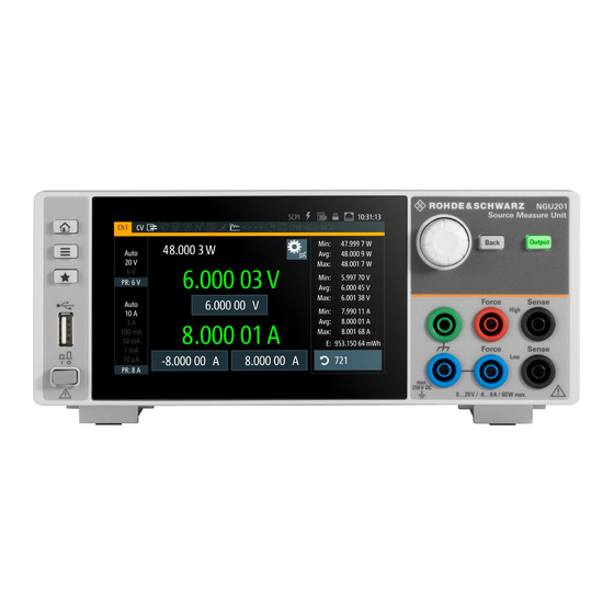
www.allice.de Allice Messtechnik GmbH ® Getting Started R&S Instrument Tour Figure 4-1: Operating positions Positioning of instrument The instrument must be positioned in a manner that allows you to disconnect the unit from the mains at any time and without restrictions. 4.1.4.2 Rack Mounting The instrument can be installed in a 19"... - Page 24 Allice Messtechnik GmbH ® Getting Started R&S Instrument Tour Figure 4-2: Front panel of NGU201 model 1 = Display with touch screen 2 = Menu control keys 3 = Rotary knob and back key 4 = Output key 5 = Output terminals...
-
Page 25: Rear Panel
8 = AC inlet with fuse holder and voltage selector 9 = Channel 1 rear panel connector. For NGU201, the last two pins are labeled as DVM+ and DVM- as an option. For NGU401, the pins are labeled as MOD+ and MOD-. - Page 26 Using both terminals at the same time can cause instrument malfunction. Digital voltmeter (DVM) The DVM+ and DVM- pins on the channel connector are available only with NGU201 model equipped with option R&S NGU-K104 (P/N: 3663.0390.02 ). Modulating signal (MOD) The MOD+ and MOD- pins on the channel connector are available only with NGU401 model.
-
Page 27: Switching On The Instrument
www.allice.de Allice Messtechnik GmbH ® Getting Started R&S Instrument Tour Option IEEE-488 (GPIB) interface (14) An IEEE-488 (GPIB) interface can be ordered with option R&S NGU-B105 (P/N: 3661.0763.02). This interface is not user installable. Digital I/O connector (15) The Digital I/O option, R&S NGU-K103 (P/N: 3662.9335.02) must be installed for this function to be available in the instrument. -
Page 28: Trying Out The Instrument
www.allice.de Allice Messtechnik GmbH ® Getting Started R&S Trying Out the Instrument To change power fuse / mains voltage setting: 1. Peel off the yellow label sticker on the AC inlet. 2. Release the latch of the fuse holder which is located at both side of the socket and pull it out. -
Page 29: Setting The Output Voltage And Current
Trying Out the Instrument Source and sink current The NGU201 is a 2 quadrant source measure unit whereas the NGU401 is a 4 quad- rant source measure unit. Both models are able to source and sink current. When the voltage across the output terminal exceeds the set voltage, current flows into the instrument. -
Page 30: Maintenance And Support
Maintenance and Support CR mode CR mode is available only with NGU201 model. CR mode is a special case of sink mode in which the instrument behaves like a con- stant resistor. Only in this mode, the display font color in the home window turns cyan. -
Page 31: Contacting Customer Support
www.allice.de Allice Messtechnik GmbH ® Getting Started R&S Maintenance and Support Instrument damage caused by cleaning agents Use a dry, lint-free cloth to clean the product. When cleaning, keep in mind that the casing is not waterproof. Do not use any liquids for cleaning. Cleaning agents, solvents (thinners, acetone), acids and bases can damage the front panel labeling, plastic parts and display. -
Page 32: Operating Basics
= Measured output voltage (negative value available only with NGU401 model) = Voltage and current measurement range = Source output resistance/emulated internal impedance = Measured output power = DVM measured value (available only as an option with NGU201 model) User Manual 1179.2531.02 ─ 02... -
Page 33: Status Bar Information
www.allice.de Allice Messtechnik GmbH ® Operating Basics R&S Display Overview 5.1.1 Status Bar Information There are two types of status bar. One shows device status information and the other shows the channel status information. Device status bar Function Description If touch input is disabled, the icon is displayed and Touchscreen highlighted in yellow. - Page 34 CV: Constant voltage mode ● CC: Constant current mode ● CR: Constant resistance mode. Available only with NGU201 model, the R&S NGU goes into this mode when operates in sink mode and the "Constant Resistance" mode is activated. Chapter 5.5, "Operation Modes", on page 42.
-
Page 35: Channel Display Area
= Source output resistance/emulated internal impedance displays in ohms (available only with NGU201 model) = Output power displays in watt = Measurement of DVM value (available only as an option R&S-NGU-K104 with NGU201 model) = "Settings" button opens instrument device/channel menu window. Long-press on the button opens the graphical view window for measurements User Manual 1179.2531.02 ─... -
Page 36: Using The Touchscreen
CC mode Active outputs are operated in a constant current mode. CR mode Available only with NGU201 model. Active outputs are operated in a constant resistance mode. This condition occurs if the set voltage is below the voltage applied externally at the output connectors (sink mode) and constant resistor is switched on in channel menu. -
Page 37: Accessing Functionality In The Home Window
www.allice.de Allice Messtechnik GmbH ® Operating Basics R&S Using the Touchscreen Swipe up and down Swipe up to scroll down, swipe down to scroll up in the menu. 5.2.2 Accessing Functionality in the Home Window The following illustrates various ways of accessing functions in the home window. 5.2.2.1 Settings Button The "Settings"... -
Page 38: Voltage And Current Inputs
www.allice.de Allice Messtechnik GmbH ® Operating Basics R&S Using the Touchscreen Figure 5-4: Navigation on home window > device/channel menu window 5.2.2.2 Voltage and Current Inputs You can directly change the voltage and current level in the respective channel display area. -
Page 39: Input Data
www.allice.de Allice Messtechnik GmbH ® Operating Basics R&S Using the Touchscreen Figure 5-5: Set voltage and current in home window 5.2.3 Input Data The R&S NGU provides an on-screen keypad for you to enter numerical values. Use the back key on the on-screen keypad to cancel input of the numerical entries. -
Page 40: Front Panel Keys
www.allice.de Allice Messtechnik GmbH ® Operating Basics R&S Front Panel Keys Figure 5-7: Alphanumeric input data 5.3 Front Panel Keys For an overview of the front panel keys, see Figure 4-2. 5.3.1 Menu Controls The menu controls keys provide navigation on the available menus in the instrument. 5.3.1.1 Home Key The [Home] key navigates to the instrument home window. - Page 41 "Arb Editor" Programs the waveform of voltage and current settings for the channel output. "Battery Model Editor" Available only as an option R&S NGU-K106 with NGU201 model. Edit new or existing battery model data. "Logging" Data logging on the instrument timestamp, voltage, current and power.
- Page 42 www.allice.de Allice Messtechnik GmbH ® Operating Basics R&S Front Panel Keys Menu Description "Appearance" Configures brightness level for screen display and frontpanel keys. "Sound" Enables or disables beeper for trigger events (e.g. error, fuse tripped, cc-mode continuous). "Licenses" Displays license information and install license options. "Device Information"...
-
Page 43: User Key
Fast data logging on the instrument timestamp, voltage and current. "Ramp" Configures the ramping time applied on the channel output. "Battery Simulator" Available only as an option R&S NGU-K106 with NGU201 model. Activation of the "Battery Simulator" function and edit new bat- tery model data. "Overcurrent Protection (OCP)"... -
Page 44: Navigation Controls
5.3.3 Output and Channel Controls The R&S NGU is a single channel source measure unit which comes in the following 2 quadrant NGU201 model and 4 quadrant NGU401 model. Both models can output source current or sink current. Function keys... -
Page 45: Operation Modes
Allice Messtechnik GmbH ® Operating Basics R&S Operation Modes Figure 5-10: Output performance graph 5.5 Operation Modes CR mode available only with NGU201 model. The R&S NGU operates in the following modes: ● constant voltage (CV) ● constant current (CC) ●... -
Page 46: Voltage And Current Priority Modes
www.allice.de Allice Messtechnik GmbH ® Operating Basics R&S Operation Modes Figure 5-11: Current limit CC mode The current I corresponds to the current setting adjustable in the instrument. If I reaches I , the instrument switches to CC mode, i.e. the output current remains constant and limited to I even if the load increases. - Page 47 www.allice.de Allice Messtechnik GmbH ® Operating Basics R&S Operation Modes Figure 5-12: Voltage priority mode In current priority mode, CPM, the output is controlled by a bipolar current control loop. In CPM, the output voltage can be set to the required positive and negative limits. Figure 5-13: Current priority mode To go into the "CPM"...
-
Page 48: Instrument Functions
6.1 Setting the Channels Voltage and Current The R&S NGU comes with the following instrument models: Model Voltage Current NGU201 0 V to 20.05 V <= 6 V: 8A, > 6 V: 3A NGU401 -20.05 V to 20.05 V <= 6 V: 8A, > 6 V: 3A... -
Page 49: Activating The Channel Output
www.allice.de Allice Messtechnik GmbH ® Instrument Functions R&S Activating the Channel Output For more information on the operation modes, see Chapter 5.5, "Operation Modes", on page 42. Figure 6-1: Voltage and current settings in the instrument 6.2 Activating the Channel Output The outputs can be switched on or off by toggling the [Output] key on the front panel. -
Page 50: Set Constant Resistance
This allows you to perform testing that requires a constant load resistor in your application. Constant resistance (CR) mode is available only with NGU201 model. 1. Press [Settings] key. The R&S NGU displays the device/channel menu window. -
Page 51: Fast Transient Response
www.allice.de Allice Messtechnik GmbH ® Instrument Functions R&S Activating the Channel Output Figure 6-3: Constant resistance dialog 6.2.2 Fast Transient Response With fast transient response, the R&S NGU is able to quickly stabilize the output volt- age upon a step change in the load current. Load transient recovery time can be switched between 30 μs ("Fast Transient Response"... -
Page 52: Output
The R&S NGU displays the "Output" dialog. Figure 6-5: Output delay dialog 6.2.3.1 Impedance Output impedance is available only with NGU201 model. The output impedance function is disabled during voltage ramp time of "Ramp" func- tion. See Chapter 6.10.2, "Ramp", on page 74. -
Page 53: Delay
www.allice.de Allice Messtechnik GmbH ® Instrument Functions R&S Activating the Channel Output 1. Select the "Impedance" menu item to configure the required values. The R&S NGU displays the "Output Impedance" dialog. 2. Set the required value. The R&S NGU displays the onscreen keypad for entry. 3. -
Page 54: Trigger Events
www.allice.de Allice Messtechnik GmbH ® Instrument Functions R&S Activating the Channel Output Figure 6-6: Output delay at the output terminals When the instrument output delay is activated, a "DELAY" red text is displayed at the channel display area. See Figure 6-7. -
Page 55: Output Mode
Sink : The R&S NGU goes to sink mode, current flows into the instrument. On the display, sink mode is in operation if negative current in shown for NGU201. However, if both voltage and current are shown as opposite signs (e.g. nega- tive voltage and positive current), it indicates that NGU401 is operated in the sink mode. -
Page 56: Current Priority Mode
3. Activate the "Current Priority Mode" menu item. The "CPM" is highlight in red at the channel status bar. The R&S NGU switches from voltage priority mode to current priority mode. Figure 6-8: NGU201 model switches from VPM to CPM User Manual 1179.2531.02 ─ 02... -
Page 57: High Capacitance Mode
www.allice.de Allice Messtechnik GmbH ® Instrument Functions R&S High Capacitance Mode Figure 6-9: NGU401 model switches from VPM to CPM 6.4 High Capacitance Mode When the R&S NGU connects to a capacitance DUT with leads, the leads and capaci- tance from the DUT forms a lowpass filter which causes current oscillation at the out- put of the source measure unit. -
Page 58: Ranges / Digital Voltmeter (Dvm)
R&S NGU-K104 (P/N: 3663.0390.02) option is required for Digital Voltmeter measure- ments. Ranges / Digital Voltmeter (DVM) is available only with NGU201 model. Sense connection has to be connected to the load for better performance. User Manual 1179.2531.02 ─ 02... - Page 59 www.allice.de Allice Messtechnik GmbH ® Instrument Functions R&S Ranges / Digital Voltmeter (DVM) Equipped with option R&S NGU-K104, the R&S NGU provides an independent digital voltmeter (DVM) to measure input voltage. See the datasheet for the full range of vol- tages that DVM supported.
- Page 60 www.allice.de Allice Messtechnik GmbH ® Instrument Functions R&S Ranges / Digital Voltmeter (DVM) Note: The "Voltage Autorange" and "Voltage Range" are not available if DVM is enabled. 4. Activate the "Enable DVM Measurement" menu item. The R&S NGU enables the DVM measurement. 5.
-
Page 61: Modulation Input
www.allice.de Allice Messtechnik GmbH ® Instrument Functions R&S Modulation Input 6.6 Modulation Input Available only with NGU401 model. Activation of modulation input disable the feature. The NGU401 model provides waveform amplifying for modulating input source such as a function generator via the MOD+ and MOD- terminal at the rear panel. -
Page 62: Battery Simulator
Battery Simulator 6.7 Battery Simulator Instrument option R&S NGU-K106 (P/N: 3663.0625.02) option is required. Battery Simulator is available only with NGU201 model. If battery simulator is active, the function safety limits cannot be used. Equipped with battery simulator option, the R&S NGU can be used as a battery source in developing products whereby battery is not ready for testing, such as phones and portable devices. - Page 63 www.allice.de Allice Messtechnik GmbH ® Instrument Functions R&S Battery Simulator Table 6-2: Battery simulator parameters Battery simulator parameters Descriptions The battery symbol represents the state of charge. The light blue bar indicates the open circuit voltage and the dark blue bar indicates the terminal voltage. The differences between both bars show the voltage drops on internal resistance.
- Page 64 www.allice.de Allice Messtechnik GmbH ® Instrument Functions R&S Battery Simulator Figure 6-14: Battery simulator dialog 4. Select the "Load from file..." to load the battery model file. The R&S NGU opens a dialog to select the source and file location. 5.
- Page 65 www.allice.de Allice Messtechnik GmbH ® Instrument Functions R&S Battery Simulator Figure 6-15: Battery model editor dialog 1. Configure the "Battery Model Editor" with the required state of charge (SoC), open- circuit voltage (Voc) and internal resistance (ESR). See also Table 6-2.
-
Page 66: Protection
www.allice.de Allice Messtechnik GmbH ® Instrument Functions R&S Protection 6.8 Protection There are various ways in which the R&S NGU protects itself and the connected load from damage due to overvoltage, overcurrent and overpower drawn by the load during testing. 1. -
Page 67: Overvoltage Protection (Ovp)
www.allice.de Allice Messtechnik GmbH ® Instrument Functions R&S Protection 4. Confirm value with the unit key (ms or s). 6.8.2 Overvoltage Protection (OVP) When the output voltage exceeds the limit set for the respective channel, an alert is triggered and the affected channel is turned off according to the settings configured in the OVP dialog. -
Page 68: Safety Limits
www.allice.de Allice Messtechnik GmbH ® Instrument Functions R&S Protection 2. Activate the "Enabled" menu item. The R&S NGU enables the OPP and displays the "Overpower Protection (OPP)" icon on the selected channel status bar information. 3. Set the required levels for OPP. The R&S NGU displays the on-screen keypad to set the value. -
Page 69: Trigger / Digital I/O
www.allice.de Allice Messtechnik GmbH ® Instrument Functions R&S Trigger / Digital I/O Figure 6-17: Safety limits dialog 2. Activate the "Enabled" menu item. The R&S NGU limits the set voltage and current level and displays the "Safety Lim- its" icon on the selected channel status bar information. 3. - Page 70 www.allice.de Allice Messtechnik GmbH ® Instrument Functions R&S Trigger / Digital I/O The trigger system has two latency types: low latency and software latency. While low latency triggers are executed faster, the software latency does not have additional requirements. The low latency actions are highlighted in bold (blue) and required to have same hard- ware channel for trigger source and trigger target.
- Page 71 www.allice.de Allice Messtechnik GmbH ® Instrument Functions R&S Trigger / Digital I/O Trigger-in parameters Source Descriptions CC, CV, CR, Protection, Sink Operation Mode If respective channel operation modes, protection event or sink mode is detected, corresponding trigger-out parameters are triggered. Figure 6-18.
- Page 72 www.allice.de Allice Messtechnik GmbH ® Instrument Functions R&S Trigger / Digital I/O Digital I/O connector The Digital I/O connector is located below the GPIB connector, see Chapter 4.2.1.2, "Rear Panel", on page 22. Figure 4-4 Table 4-2 for the Digital I/O connector and pins layout. 1.
- Page 73 www.allice.de Allice Messtechnik GmbH ® Instrument Functions R&S Trigger / Digital I/O Figure 6-21: Digital Out dialog 7. Depending on your requirements, select the digital output accordingly. The Digital I/O output pins OUT1 can be set directly by the SCPI commands. See on page 158.
-
Page 74: Advanced Features
www.allice.de Allice Messtechnik GmbH ® Instrument Functions R&S Advanced Features 6.10 Advanced Features Arbitrary function If Arbitrary function is enabled, the channel voltage, current setting and safety limit set- tings are disabled. Chapter 6.1, "Setting the Channels Voltage and Current", on page 45. - Page 75 www.allice.de Allice Messtechnik GmbH ® Instrument Functions R&S Advanced Features Alternatively, select "New file" to edit a new arbitrary file. The R&S NGU opens the arbitrary editor dialog to edit the arbitrary file. 7. Select "Load" to load the selected file. The R&S NGU loads the selected arbitrary file.
- Page 76 www.allice.de Allice Messtechnik GmbH ® Instrument Functions R&S Advanced Features Figure 6-23: Arbitrary editor dialog 1. Configure the "Arb Editor" with the required voltage, current and duration. The R&S NGU displays the on-screen keypad for data entry. 2. Confirm values with the unit keys. 3.
-
Page 77: Ramp
Each channel has an independent ramp configuration. See Figure 6-24. Internal resistance Applicable only with NGU201 model. The internal resistance control is only applied after the ramp is processed until the con- figured target value is reached. Chapter 6.2.1, "Set Constant Resistance",... -
Page 78: User Key
www.allice.de Allice Messtechnik GmbH ® Instrument Functions R&S User Key 3. Select "Ramp" from the menu. The R&S NGU displays the "Ramp" dialog. Figure 6-25: Ramp dialog 4. Activate the "Enabled" menu item. The R&S NGU enables the Ramp function and displays the "Ramp" icon on the channel status bar information. -
Page 79: Screenshot
www.allice.de Allice Messtechnik GmbH ® Instrument Functions R&S Screenshot Figure 6-26: User button action 4. Select the "User Button Action" to configure the user action. The R&S NGU displays a dialog to configure the user action. 5. Select the required user action. ●... -
Page 80: Data Logging
4. Select the "Save Location" to configure the screenshot file location. ● "Auto": Target folder is set to default file location: – With USB stick detected: /USB1A/NGU201/screenshot for NGU201 model /USB1A/NGU401/screenshot for NGU401 model – Without USB stick detected: /int/screenshot ●... - Page 81 www.allice.de Allice Messtechnik GmbH ® Instrument Functions R&S Data Logging 4. Select the "Save Location" menu item to select the predefined target folder for data logger. ● "Auto": "Target Folder" is auto-selected. If no USB stick is detected, "Target Folder" is set to internal memory ("int") par- tition.
-
Page 82: Fastlog
www.allice.de Allice Messtechnik GmbH ® Instrument Functions R&S FastLog The R&S NGU activates the logging and disables the settings for file saved loca- tion and logging mode settings. 9. Applicable only with R&S NGU-K103, activate the "Triggered" menu item if data logging is required under triggered conditions. -
Page 83: Csv Settings
www.allice.de Allice Messtechnik GmbH ® Instrument Functions R&S CSV Settings 4. Select "Enabled" to activate the "FastLog" function. The R&S NGU starts the fast logging and displays the "Fast Logging" icon at the device status bar information. 5. Select "Triggered" to "ON" if you want "FastLog" to be enabled by a trigger event. 6. - Page 84 www.allice.de Allice Messtechnik GmbH ® Instrument Functions R&S CSV Settings Figure 6-29: Sample of data logging 1. Select "CSV Settings" from "Device" menu. The R&S NGU displays the "CSV Settings" dialog. Figure 6-30: CSV settings dialog 2. Set the required CSV parameters. The R&S NGU displays the respective dialog to set the CSV parameters.
-
Page 85: Graphical View Window
www.allice.de Allice Messtechnik GmbH ® Instrument Functions R&S Graphical View Window CSV settings Selective fields in the dialog "Error Designator" "IEE Float (NaN)", "Empty" "Line End Marker" "CR/LF", "LF" 6.16 Graphical View Window The graphical view measurement is a time-based measurement that allows you to vis- ualize measurements on available data sources. - Page 86 www.allice.de Allice Messtechnik GmbH ® Instrument Functions R&S Graphical View Window Figure 6-32: Device menu 3. Select any of the configuration slots to configure the measurement parameters. Note: The DVM measurement must be enabled for the measurement to be availa- ble in the configuration dialog.
-
Page 87: File Manager
www.allice.de Allice Messtechnik GmbH ® Instrument Functions R&S File Manager 8. Select "Apply" to confirm the configuration. 9. Select "Close" to exit configuration dialog. 6.17 File Manager The "File Manager" provides file transfer functions between USB stick and internal memory of the instrument. You can copy and delete files in both USB stick and internal memory of the instrument. -
Page 88: Store And Recall
www.allice.de Allice Messtechnik GmbH ® Instrument Functions R&S Store and Recall 4. Select the file that you want to copy or delete. 5. Select the required action in the file manager dialog. Table 6-6. 6. To view the selected file information, long-press on the selected filename in the file manager dialog. - Page 89 www.allice.de Allice Messtechnik GmbH ® Instrument Functions R&S Store and Recall In addition of the auto saved instrument settings, the following instrument settings are stored or recalled in the internal memory: ● Set voltage and current level ● Settings in the Protection Function, Safety Limits ●...
-
Page 90: Interfaces
www.allice.de Allice Messtechnik GmbH ® Instrument Functions R&S Interfaces The R&S NGU displays a popup message. 2. Select "Yes" to overwrite instrument settings to factory default. The R&S NGU resets current instrument settings to factory default. 3. The R&S NGU displays a popup message to show that all settings are reset to fac- tory default. -
Page 91: Network Connection
www.allice.de Allice Messtechnik GmbH ® Instrument Functions R&S Interfaces Figure 6-36: Interfaces dialog 4. Select the connected interface (Network, USB Class GPIB Address) to configure the necessary parameters required. ● Network Connection....................88 ● Connection......................91 ● GPIB Address......................92 6.19.1 Network Connection There are two methods to establish a local area network (LAN) connection with the R&S NGU for remote control operation. -
Page 92: Lan Connection
www.allice.de Allice Messtechnik GmbH ® Instrument Functions R&S Interfaces ● "SCPI Raw Port": A port number used to open a raw TCP/IP connection to send raw SCPI commands to the instrument ● "Hostname": The name assigned to the instrument used to identify it in the net- work When the connection is available, the network icon is highlighted in white on the device status bar information. - Page 93 www.allice.de Allice Messtechnik GmbH ® Instrument Functions R&S Interfaces The R&S NGU displays the "LAN" dialog. Note: The "MAC Address" is fixed. Figure 6-38: Ethernet settings dialog 3. Set the "DHCP & Auto-IP". ● "ON": Enables DHCP for automatic network parameter distribution and shows the values of the IP Address.
-
Page 94: Usb Connection
www.allice.de Allice Messtechnik GmbH ® Instrument Functions R&S Interfaces 8. Select "Apply Configuration" to apply the changes. 6.19.2 USB Connection Change of USB class If a change in "USB Class" is detected (i.e. from "TMC" to "CDC" or vice versa), the rebooting of instrument is necessary to load the correct USB driver. -
Page 95: Gpib Address
www.allice.de Allice Messtechnik GmbH ® Instrument Functions R&S Interfaces 6.19.3 GPIB Address Instrument option R&S NGU-B105 (P/N: 3652.6356.02) option needs to be installed for the remote com- mand of R&S NGU via GPIB interface. The GPIB interface, sometimes called the General Purpose Interface Bus (GPIB), is a general purpose digital interface system that can be used to transfer data between two or more devices. -
Page 96: General Instrument Settings
www.allice.de Allice Messtechnik GmbH ® Instrument Functions R&S General Instrument Settings 6.20 General Instrument Settings The following chapters provide the general instrument information and utilities services in "Device" menu. 1. Press [Settings] key. The R&S NGU displays the device/channel menu window. 2. -
Page 97: Appearance Settings
www.allice.de Allice Messtechnik GmbH ® Instrument Functions R&S General Instrument Settings If the installation is successful, the option is displayed in the "Active" window. To manually enter the key code, proceed as follows: 1. Select "Add" key to invoke the license key on-screen keyboard. Figure 6-42: License key on-screen keyboard 2. -
Page 98: Sound Settings
www.allice.de Allice Messtechnik GmbH ® Instrument Functions R&S General Instrument Settings Figure 6-43: Appearance dialog 6.20.3 Sound Settings 1. Select the "Sound Settings" to set sound settings. The R&S NGU displays the sound settings dialog. Figure 6-44: Sound settings dialog 2. -
Page 99: Date And Time
www.allice.de Allice Messtechnik GmbH ® Instrument Functions R&S General Instrument Settings 6.20.4 Date and Time The time is regarded as UTC. There is no timezone selectable. 1. Select the "Date & Time" to set date and time format. The R&S NGU displays the date and time dialog. Figure 6-45: Date and time setting dialog 2. -
Page 100: Update Device
www.allice.de Allice Messtechnik GmbH ® Instrument Functions R&S General Instrument Settings Figure 6-46: Device information dialog Device information Description Model Model of the instrument. Instrument orderable part number. Serial No. Unique identification number for the instrument. Version Software version that is installed in the instrument. Hardware IDs Unique serial number of the front and mainboard of the instrument. -
Page 101: Device Documentation
www.allice.de Allice Messtechnik GmbH ® Instrument Functions R&S Device Documentation Figure 6-47: Update device dialog 2. Select the source and file location to update instrument firmware. 3. Select "UPDATE" to update the instrument firmware. The R&S NGU updates the instrument firmware accordingly. 6.21 Device Documentation You can retrieve the R&S NGU Open Source Acknowledgment documentation from the instrument documentation folder /int/documentation. -
Page 102: Remote Control Commands
www.allice.de Allice Messtechnik GmbH ® Remote Control Commands R&S Common Setting Commands 7 Remote Control Commands This chapter provides the description of all remote commands available for the R&S NGU series. The commands are sorted according to the menu structure of the instrument. - Page 103 www.allice.de Allice Messtechnik GmbH ® Remote Control Commands R&S Common Setting Commands Parameters: <Value> Range: 0 to 255 *ESR? Event status read Returns the contents of the event status register in decimal form and then sets the reg- ister to zero. Return values: <Contents>...
- Page 104 www.allice.de Allice Messtechnik GmbH ® Remote Control Commands R&S Common Setting Commands *SRE <Contents> Service request enable Sets the service request enable register to the indicated value. This command deter- mines under which conditions a service request is triggered. Parameters: <Contents>...
-
Page 105: System Settings Commands
www.allice.de Allice Messtechnik GmbH ® Remote Control Commands R&S System Settings Commands 7.2 System Settings Commands The SYSTem subsystem contains the commands for general functions, which do not affect signal generation directly................... 102 SYSTem:BEEPer:CURRent:STATe ................102 SYSTem:BEEPer:PROTection:STATe ............... 102 SYSTem:BEEPer:PROTection[:IMMediate] .................... - Page 106 www.allice.de Allice Messtechnik GmbH ® Remote Control Commands R&S System Settings Commands SYSTem:BEEPer:STATe <Mode> SYSTem:BEEPer:STATe? Sets or queries the beeper tone. Parameters: <Mode> Control beeper is activated. Control beeper is deactivated. Example: SYSTem:BEEPer:STATe 1 The front panel control beeper is activated. Example: SYSTem:BEEPer:STATe? Queries the state of the front panel control beeper.
-
Page 107: Display Commands
www.allice.de Allice Messtechnik GmbH ® Remote Control Commands R&S Display Commands Example: SYSTem:KEY:BRIGhtness 1.0 SYSTem:KEY:BRIGhtness? -> 1.0 Returns key brightness value: 1.0. SYSTem:DATE <year>, <month>, <day> SYSTem:DATE? Sets or queries the system date. Parameters: <year> Sets year of the date. <month>... -
Page 108: Trigger Commands
www.allice.de Allice Messtechnik GmbH ® Remote Control Commands R&S Trigger Commands Parameters: <brightness> Displays brightness for the instrument. Range: 0.0 to 1.0 Increment: 0.1 *RST: Example: DISPlay:BRIGhtness 0.5 DISPlay:BRIGhtness? -> 0.5 Returns the display brightness value. DISPlay[:WINDow]:TEXT:CLEar Clears the text message box on the front display. Usage: Setting only DISPlay[:WINDow]:TEXT[:DATA] <string>... - Page 109 www.allice.de Allice Messtechnik GmbH ® Remote Control Commands R&S Trigger Commands TRIGger[:SEQuence][:IMMediate]:SOURce <arg0> TRIGger[:SEQuence][:IMMediate]:SOURce? <arg0> Sets or queries the trigger source. Figure 6-18. Parameters for setting and query: <arg0> OUTPut | OMODe | DIO OUTPut Trigger source is from the output channel. OMODe Trigger source is from the different modes (CC, CR, CV, Sink, OVP, OCP, OPP and OTP) detected from the output channel.
-
Page 110: Configuration Commands
www.allice.de Allice Messtechnik GmbH ® Remote Control Commands R&S Configuration Commands If respective channel operation mode is detected in CV mode, corresponding trigger-out parameters are triggered. If respective channel operation mode is detected in CR mode, corresponding trigger-out parameters are triggered. SINK If respective channel operation mode is detected in sink mode, corresponding trigger-out parameters are triggered. - Page 111 www.allice.de Allice Messtechnik GmbH ® Remote Control Commands R&S Configuration Commands Example: Configuring the output voltage This example contains all commands to configure and query the output voltage. // ************************************************ // Set upper or lower voltage safety limit // ************************************************ //sets the safety limits to enable ALIM 1 //queries the safety limits state...
- Page 112 www.allice.de Allice Messtechnik GmbH ® Remote Control Commands R&S Configuration Commands Parameters for setting and query: <Channel list> <list> Example: ALIM 1, (@1) Activates the safety limit state at channel 1 Example: Example "Configuring the output voltage" on page 112. [SOURce:]VOLTage[:LEVel][:IMMediate]:ALIMit:LOWer <voltage>...
- Page 113 www.allice.de Allice Messtechnik GmbH ® Remote Control Commands R&S Configuration Commands Parameters for setting and query: <Channel list> <list> Example: VOLT:ALIM:UPP? (@1) Queries the upper safety limit for voltage at channel 1. Example: Example "Configuring the output voltage" on page 112. [SOURce:]CURRent[:LEVel][:IMMediate]:ALIMit:LOWer <current>...
-
Page 114: Voltage Setting
www.allice.de Allice Messtechnik GmbH ® Remote Control Commands R&S Configuration Commands *RST: 6.010E+00 Parameters for setting and query: <Channel list> <list> Example: CURR:ALIM:UPP? (@1) Queries the upper safety limit for current at channel 1. Example: Example "Configuring the current output" on page 116. - Page 115 www.allice.de Allice Messtechnik GmbH ® Remote Control Commands R&S Configuration Commands Example: Configuring the output voltage This example contains all commands to configure and query the output voltage. // ************************************************ // Set upper or lower voltage safety limit // ************************************************ //sets the safety limits to enable ALIM 1 //queries the safety limits state...
- Page 116 www.allice.de Allice Messtechnik GmbH ® Remote Control Commands R&S Configuration Commands // queries the voltage step size VOLT:STEP? // response: "4.000" ............113 [SOURce:]VOLTage[:LEVel][:IMMediate][:AMPLitude] ..........113 [SOURce:]VOLTage[:LEVel][:IMMediate]:STEP[:INCRement] ........... 114 SOURce:VOLTage:NEGative[:LEVel][:IMMediate][:AMPLitude] [SOURce:]VOLTage[:LEVel][:IMMediate][:AMPLitude] <voltage> [SOURce:]VOLTage[:LEVel][:IMMediate][:AMPLitude]? [<Channel list>] Sets or queries the voltage value of the selected channel. Parameters: <voltage>...
- Page 117 www.allice.de Allice Messtechnik GmbH ® Remote Control Commands R&S Configuration Commands <numeric value> Step value in V. DEF | DEFault Default value of stepsize. Range: 0.001 to 5.000 Increment: 0.001 *RST: 0.100 Default unit: V Parameters for setting and query: <stepsize>...
-
Page 118: Current Setting
www.allice.de Allice Messtechnik GmbH ® Remote Control Commands R&S Configuration Commands Example: SOUR:VOLT:NEG? (@1) Queries the negarive voltage at channel 1. Example: Example "Configuring the output voltage" on page 112. 7.5.3 Current Setting The SOURce:CURRent subsystem contains the commands for setting the current limit of the output channels. - Page 119 www.allice.de Allice Messtechnik GmbH ® Remote Control Commands R&S Configuration Commands Example: Configuring the current output // ************************************************ // Set upper or lower current safety limit // ************************************************ //sets the safety limits to enable ALIM 1 //queries the safety limits state ALIM? //response: "1"...
- Page 120 www.allice.de Allice Messtechnik GmbH ® Remote Control Commands R&S Configuration Commands ..........117 [SOURce:]CURRent[:LEVel][:IMMediate]:STEP[:INCRement] ............117 [SOURce:]CURRent[:LEVel][:IMMediate][:AMPLitude] ...........118 SOURce:CURRent:NEGative[:LEVel][:IMMediate][:AMPLitude] [SOURce:]CURRent[:LEVel][:IMMediate]:STEP[:INCRement] <stepsize> [SOURce:]CURRent[:LEVel][:IMMediate]:STEP[:INCRement]? [<Optional default step query>] Sets or queries the incremental step size for the command. CURR UP | CURR DOWN Setting parameters: <stepsize>...
- Page 121 www.allice.de Allice Messtechnik GmbH ® Remote Control Commands R&S Configuration Commands Increases current by a defined step size. See [SOURce: ]CURRent[:LEVel][:IMMediate]:STEP[:INCRement] on page 117. DOWN Decreases current by a defined step size. See [SOURce: ]CURRent[:LEVel][:IMMediate]:STEP[:INCRement] on page 117. Parameters for setting and query: <Channel list>...
-
Page 122: Resistance Setting
www.allice.de Allice Messtechnik GmbH ® Remote Control Commands R&S Configuration Commands 7.5.4 Resistance Setting The SOURce:RESistance subsystem contains the commands for setting the resist- ance limit of the output channels. The default unit is ohms. Example: Configuring the resistance limit // ************************************************ // Set the resistance value // ************************************************... -
Page 123: Combined Setting Of Voltage And Current Setting
www.allice.de Allice Messtechnik GmbH ® Remote Control Commands R&S Configuration Commands Increases resistance by a defined step size. DOWN Decreases resistance by a defined step size. Increment: 0.1 ohms Default unit: ohms Parameters for setting and query: <Channel list> <list> Example: RES? (@1) Queries the constant resistance target value at channel 1. -
Page 124: Output Setting
www.allice.de Allice Messtechnik GmbH ® Remote Control Commands R&S Configuration Commands MIN | MINimum Min voltage at 0.000 V. MAX | MAXimum Max value for voltage at 20.050V. DEF | DEFault Default voltage. *RST: 1.000 Default unit: V <current> <numeric value> | MIN | MINimum | MAX | MAXimum | DEFault <numeric value>... -
Page 125: Output:general[:State]
www.allice.de Allice Messtechnik GmbH ® Remote Control Commands R&S Configuration Commands Example: Activating the channels You can activate a selected channel and turn on or off the outputs either individually or all outputs simultaneously. This example lists all ways how you can activate and query the outputs. -
Page 126: Output[:State]
www.allice.de Allice Messtechnik GmbH ® Remote Control Commands R&S Configuration Commands OUTPut[:STATe] <state> OUTPut[:STATe]? [<Channel list>] Sets or queries the output state of the previous selected channels. Parameters: <state> Switches off previous selected channels. Switches on previous selected channels. Parameters for setting and query: <Channel list>... -
Page 127: Output:delay[:State]
www.allice.de Allice Messtechnik GmbH ® Remote Control Commands R&S Configuration Commands OUTPut:DELay[:STATe] <state> OUTPut:DELay[:STATe]? [<Channel list>] Sets or queries the output delay state for the selected channel. Parameters: <state> Deactivates output delay for the selected channel. Activates output delay for the selected channel. Parameters for setting and query: <Channel list>... -
Page 128: Output:impedance:state
www.allice.de Allice Messtechnik GmbH ® Remote Control Commands R&S Configuration Commands MIN | MINimum Minimum value of the impedance at -0.05 ohms. MAX | MAXimum Maximum value of the impedance at 100 ohms. Default value of the impedance at 0 ohms. *RST: Default unit: ohm Parameters for setting and query:... -
Page 129: Output:select
www.allice.de Allice Messtechnik GmbH ® Remote Control Commands R&S Configuration Commands AUTO If operates in auto mode, the R&S NGU goes into sink or source mode depending on the voltage across the output terminal. If voltage across the output terminal exceeds the set voltage, cur- rent flows into the instrument, e.g. -
Page 130: Range/Dvm Setting
OUTPut:TRIG:BEH? (@1) Queries output behavior of trigger event at channel 1. 7.5.7 Range/DVM Setting The DVM and range settings are available only with NGU201 model equipped with R&S NGU-K104 (P/N: 3663.0390.02). The SOUR:VOLT:DVM contains commands for activating the DVM function. - Page 131 www.allice.de Allice Messtechnik GmbH ® Remote Control Commands R&S Configuration Commands ................... 128 [SOURce:]VOLTage:DVM[:STATe] ..................128 SENSe:CURRent:RANGe:AUTO ...................129 SENSe:CURRent:RANGe[:UPPer] ..................129 SENSe:VOLTage:RANGe:AUTO ................... 129 SENSe:VOLTage:RANGe[:UPPer] [SOURce:]VOLTage:DVM[:STATe] <arg0>[, <Channel list>] [SOURce:]VOLTage:DVM[:STATe]? [<Channel list>] Sets or queries digital voltmeter measurements. Parameters: <arg0> Enables digital voltmeter measurement. Disables digital voltmeter measurement.
- Page 132 www.allice.de Allice Messtechnik GmbH ® Remote Control Commands R&S Configuration Commands SENSe:CURRent:RANGe[:UPPer] <arg0>[, <Channel list>] SENSe:CURRent:RANGe[:UPPer]? [<Channel list>] Sets or queries the current range for measurement. There is a selection of 10 A, 1 A, 100 mA and 10 mA range. Parameters: <arg0>...
-
Page 133: Source Priority Mode Setting
www.allice.de Allice Messtechnik GmbH ® Remote Control Commands R&S Configuration Commands Parameters for setting and query: <Channel list> <list> Example: SENS:VOLT:RANG 20 Sets the instrument to the 20 V measurement accuracy. Refers to datasheet for the measurement accuracy in the 20 V range. -
Page 134: Power Line Cycle Setting
www.allice.de Allice Messtechnik GmbH ® Remote Control Commands R&S Configuration Commands MIN | MINimum Minimum value of the modulation gain. MAX | MAXimum Maximum value of the modulation gain Increases gain by a defined step size. DOWN Decreases gain by a defined step size. <arg1>... - Page 135 www.allice.de Allice Messtechnik GmbH ® Remote Control Commands R&S Configuration Commands CURR:PROT? // response: 1 // ************************************************ // Set a delay time for the overcurrent protection. The delay time // takes effect when the channel output is turned on. // ************************************************ // sets 50 ms delay for the overcurrent protection CURR:PROT:DEL 50 // queries the currently set delay time of the overcurrent protection...
- Page 136 www.allice.de Allice Messtechnik GmbH ® Remote Control Commands R&S Configuration Commands CURR:PROT:TRIP? //response: 1 OCP is tripped //response: 0 OCP is not tripped //resets a tripped OCP CURR:PROT:CLEar ................133 [SOURce:]CURRent:PROTection:CLEar ..............133 [SOURce:]CURRent:PROTection:DELay:INITial ................134 [SOURce:]CURRent:PROTection:DELay ..............134 [SOURce:]CURRent:PROTection:TRIPped? .................135 [SOURce:]CURRent:PROTection[:STATe] .......................135 FUSE:DELay:INITial...
- Page 137 www.allice.de Allice Messtechnik GmbH ® Remote Control Commands R&S Configuration Commands Example: CURR:PROT:DEL:INIT? (@1) Queries initial fuse delay time at channel 1. Example: Example "Configuring the overcurrent protection" on page 131. [SOURce:]CURRent:PROTection:DELay <New value for voltage>[, <Channel list>] [SOURce:]CURRent:PROTection:DELay? [<Channel list>] Sets or queries the fuse delay time.
- Page 138 www.allice.de Allice Messtechnik GmbH ® Remote Control Commands R&S Configuration Commands [SOURce:]CURRent:PROTection[:STATe] <arg0>[, <Channel list>] [SOURce:]CURRent:PROTection[:STATe]? [<Channel list>] Sets or queries the OCP state. Parameters: <arg0> Activates the OCP state. deactivates the OCP state. Parameters for setting and query: <Channel list> <list>...
- Page 139 www.allice.de Allice Messtechnik GmbH ® Remote Control Commands R&S Configuration Commands FUSE:DELay[:BLOWing] <delay> FUSE:DELay[:BLOWing]? [<Channel list>] Sets or queries delay time for the fuse to take effect. Parameters: <delay> <numeric value> | MIN | MINimum | MAX | MAXimum | <list> <numeric value>...
-
Page 140: Ovp Setting
www.allice.de Allice Messtechnik GmbH ® Remote Control Commands R&S Configuration Commands Parameters for setting and query: <Channel list> <list> Example: FUSE? (@1) Queries fuse state at channel 1. Example: For alternative command, see Example "Configuring the over- current protection" on page 131 7.5.12 OVP Setting The VOLTage:PROTection subsystem contains the commands for setting the over- voltage protection parameters for the output channels. - Page 141 www.allice.de Allice Messtechnik GmbH ® Remote Control Commands R&S Configuration Commands Example: Configuring the overvoltage protection // ************************************************ // Set the overvoltage protection value // ************************************************ //activates the OVP VOLT:PROT 1 // selects a channel and sets the OVP VOLT:PROT:LEV 5 // queries the output overvoltage value VOLT:PROT:LEV? // response: 5...
- Page 142 www.allice.de Allice Messtechnik GmbH ® Remote Control Commands R&S Configuration Commands [SOURce:]VOLTage:PROTection[:STATe] <state> [SOURce:]VOLTage:PROTection[:STATe]? [<Channel list>] Sets or queries the OVP state of the previous selected channel. Parameters: <state> OPP is deactivated OPP is activated Parameters for setting and query: <Channel list>...
-
Page 143: Opp Setting
www.allice.de Allice Messtechnik GmbH ® Remote Control Commands R&S Configuration Commands Range: 0.001 to 20.05 *RST: 20.05 Default unit: V Parameters for setting and query: <Channel list> <list> Example: VOLT:PROT:LEV? (@1) Queries overvoltage protection value at channel 1. Example: Example "Configuring the overvoltage protection" on page 138. - Page 144 www.allice.de Allice Messtechnik GmbH ® Remote Control Commands R&S Configuration Commands Example: Configuring the overpower protection // ************************************************ // Set the overpower protection value // ************************************************ //activates the OPP POW:PROT 1 // sets the OPP POW:PROT:LEV 5 // queries the output overvoltage value POW:PROT:LEV? // response: 5 // queries the OPP state...
- Page 145 www.allice.de Allice Messtechnik GmbH ® Remote Control Commands R&S Configuration Commands OPP is activated Parameters for setting and query: <Channel list> <list> Example: POW:PROT? (@1) Queries OPP state at channel 1. Example: Example "Configuring the overpower protection" on page 141. [SOURce:]POWer:PROTection:CLEar [<Channel list>] Resets the OPP state of the selected channel.
-
Page 146: Usb Class Setting
www.allice.de Allice Messtechnik GmbH ® Remote Control Commands R&S Measurement Commands Example: POW:PROT:LEV? (@1) Queries OPP value at channel 1. [SOURce:]POWer:PROTection:TRIPped? [<Channel list>] Queries the OPP state of the selected channel. Parameters: <Channel list> <list> Example: POW:PROT:TRIP? Response 1, the OPP is tripped. Response 0, the OPP is not tripped. - Page 147 www.allice.de Allice Messtechnik GmbH ® Remote Control Commands R&S Measurement Commands ................146 MEASure[:SCALar]:CURRent[:DC]? ................. 146 MEASure[:SCALar]:CURRent[:DC]:AVG? ................ 146 MEASure[:SCALar]:CURRent[:DC]:MAX? ................146 MEASure[:SCALar]:CURRent[:DC]:MIN? ..............146 MEASure[:SCALar]:CURRent[:DC]:STATistic? ................... 147 MEASure[:SCALar]:POWer? ..................147 MEASure[:SCALar]:POWer:AVG? ..................147 MEASure[:SCALar][:POWer]:AVG? ................... 147 MEASure[:SCALar]:POWer:MAX? ................. 147 MEASure[:SCALar][:POWer]:MAX? ..................147 MEASure[:SCALar]:POWer:MIN? ..................
- Page 148 www.allice.de Allice Messtechnik GmbH ® Remote Control Commands R&S Measurement Commands Activates the energy counter. Deactivates the energy counter. Parameters for setting and query: <Channel list> <list> Example: MEAS:ENER:STAT ON MEAS:ENER:STAT? MEAS:ENER:STAT? -> 1 Energy counter of Ch1 is enabled. Example: MEAS:ENER:STAT? (@1) Queries the energy counter state at channel 1.
-
Page 149: Measure[:Scalar]:Current[:Dc]
www.allice.de Allice Messtechnik GmbH ® Remote Control Commands R&S Measurement Commands MEASure[:SCALar]:CURRent[:DC]? [<Channel list>] Queries the currently measured current of the selected channel. Parameters: <Channel list> <list> Example: MEAS:CURR? -> 1.000E +00 Example: MEAS:CURR? (@1) Queries the currently measured current at channel 1. Usage: Query only MEASure[:SCALar]:CURRent[:DC]:AVG? [<Channel list>]... -
Page 150: Measure[:Scalar]:Power
www.allice.de Allice Messtechnik GmbH ® Remote Control Commands R&S Measurement Commands Parameters: <Channel list> <list> Example: MEAS:CURR:DC:STAT? Queries the current statistics at channel 1. Example: MEAS:CURR:DC:STAT? (@1) Queries the current statistics at channel 1. Usage: Query only MEASure[:SCALar]:POWer? [<Channel list>] Queries the currently emitted power of the selected channel. -
Page 151: Measure[:Scalar]:Power:statistic
www.allice.de Allice Messtechnik GmbH ® Remote Control Commands R&S Measurement Commands MEASure[:SCALar]:POWer:STATistic? [<Channel list>] Queries the power statistics of the selected channel. Parameters: <Channel list> <list> Example: MEAS:CURR:DC:STAT? Queries the power statistics at channel 1. Example: MEAS:POW:STAT? (@1) Queries the power statistics at channel 1. Usage: Query only MEASure[:SCALar][:VOLTage][:DC]? [<Channel list>]... -
Page 152: Advanced Operating Commands
Queries the voltage statistics at channel 1. Usage: Query only MEASure:VOLTage:DVM? [<Channel list>] Queries the voltmeter measurement (if DVM is enabled). The DVM is available only with NGU201 model equipped with R&S NGU-K104 (P/N: 3663.0390.02). Query parameters: <Channel list> <list>... -
Page 153: Arbitrary
www.allice.de Allice Messtechnik GmbH ® Remote Control Commands R&S Advanced Operating Commands 7.7.1 Arbitrary The ARBitrary subsystem contains the commands for configuring an arbitrary sequence for the output channels. Example: Configuring an arbitrary sequence This programming example generates an arbitrary sequence for a selected channel. The sequence starts at 1 V and 1 A for 1 sec, and both values are incremented each second by 1. - Page 154 www.allice.de Allice Messtechnik GmbH ® Remote Control Commands R&S Advanced Operating Commands .....................153 ARBitrary:REPetitions ......................153 ARBitrary:RESTore ......................153 ARBitrary:SAVE ......................154 ARBitrary:STARt ......................154 ARBitrary:STOP ....................... 154 ARBitrary:TRANsfer ...................154 ARBitrary:TRIGgered:MODE ..................155 ARBitrary:TRIGgered[:STATe] ARBitrary[:STATe] <state> ARBitrary[:STATe]? [<Channel list>] Sets or queries the arbitrary function for the previous selected channel. Parameters: <state>...
- Page 155 www.allice.de Allice Messtechnik GmbH ® Remote Control Commands R&S Advanced Operating Commands ARBitrary:CLEar Clears the current arbitrary table data for the selected channel. Example: Example "Configuring an arbitrary sequence" on page 150. Usage: Event ARBitrary:DATA <data> Sets or queries the arbitrary points for the previous selected channel. Max. 4096 arbi- trary points can be defined.
- Page 156 www.allice.de Allice Messtechnik GmbH ® Remote Control Commands R&S Advanced Operating Commands ARBitrary:LOAD Loads an arbitrary table from a file (filename specified with ARB:FNAM) Example: ARB:DATA 10,1,0.5,0 ARB:REP 10 ARB:FNAM "ARB03.CSV“,INT ARB:SAVE ARB:LOAD Loads an arbitrary data from filename ARB03.CSV. Usage: Event ARBitrary:REPetitions <repetition_rate>...
- Page 157 www.allice.de Allice Messtechnik GmbH ® Remote Control Commands R&S Advanced Operating Commands Usage: Event ARBitrary:STARt Enables arbitrary. Command is same as ARB:STAT 1. Usage: Event Example "Configuring an arbitrary sequence" on page 150. ARBitrary:STOP Disables arbitrary. Command is same as ARB:STAT 0. Usage: Event Example "Configuring an arbitrary sequence"...
-
Page 158: Ramp
www.allice.de Allice Messtechnik GmbH ® Remote Control Commands R&S Advanced Operating Commands ARBitrary:TRIGgered[:STATe] <state> ARBitrary:TRIGgered[:STATe]? Sets or queries the arbitrary trigger mode. Parameters: <state> OFF - Trigger input is deactivated. ON - Trigger input is activated. Example: ARB:TRIG ON ARB:TRIG? -> 1 Activates the Ch1 trigger mode for arbitrary function. -
Page 159: Digital I/O
www.allice.de Allice Messtechnik GmbH ® Remote Control Commands R&S Advanced Operating Commands [SOURce:]VOLTage:RAMP:DURation <duration> [SOURce:]VOLTage:RAMP:DURation? [<Channel list>] Sets or queries the duration of the voltage ramp. Parameters: <duration> <numeric value> | MIN | MINimum | MAX | MAXimum | DEF | DEFault | <list>... - Page 160 www.allice.de Allice Messtechnik GmbH ® Remote Control Commands R&S Advanced Operating Commands Parameters: <arg0> CC | CV | CR | SINK | PROTection | OUTPut If "OUTPut" is selected, the "fault output" will be active if the out- put of the selected channel is off. Example: DIO:FAUL:SOUR PROT Sets the "operation modes"...
- Page 161 www.allice.de Allice Messtechnik GmbH ® Remote Control Commands R&S Advanced Operating Commands TRIGger Selected channel external trigger signal is used as the digital output source. FORCed Selected output is forced to high level and can be switched by on page 158 command. DIO:OUTPut[:STATe] Parameters for setting and query: <arg0>...
-
Page 162: Battery Simulation
® Remote Control Commands R&S Advanced Operating Commands 7.7.4 Battery Simulation Available only with NGU201 model. The BATT subsystem contains the commands for configuring the battery simulator and battery model function for the output channels..................159 BATTery:SIMulator:CAPacity? ................... 159 BATTery:SIMulator:CAPacity:LIMit ..................160... -
Page 163: Battery:simulator:current
www.allice.de Allice Messtechnik GmbH ® Remote Control Commands R&S Advanced Operating Commands Parameters: <arg0> Defines the full battery capacity. Example: BATT:SIM:CAP:LIM 100 Defines 100 % full battery capacity for channel 1 battery simula- tor. BATTery:SIMulator:CURRent? Queries the current (A) of battery simulator. Example: BATT:SIM:CURR? Returns current from channel 1 battery simulator. -
Page 164: Battery:simulator:resistance
www.allice.de Allice Messtechnik GmbH ® Remote Control Commands R&S Advanced Operating Commands Parameters: <arg0> Sets the current limit at regular charge level. Example: BATT:SIM:CURR:LIM:REG? Returns current limit at regular charge level for channel 1. BATTery:SIMulator:RESistance? Queries the battery simulator internal resistance (ESR). Example: BATT:SIMU:RES? Queries channel 1 of battery simulator internal resistance. -
Page 165: Battery:simulator:voc:full
www.allice.de Allice Messtechnik GmbH ® Remote Control Commands R&S Advanced Operating Commands BATTery:SIMulator:VOC:FULL? Queries the open circuit voltage (Voc) for full SoC, i.e SoC = 100 %. Example: BATT:SIM:VOC:FULL? Returns 1 if channel 1 battery simulator is fully charge. Usage: Query only BATTery:SIMulator[:ENABle] <arg0>[, <Channel list>] BATTery:SIMulator[:ENABle]? [<Channel list>]... -
Page 166: Battery:model:current:limit:eod
www.allice.de Allice Messtechnik GmbH ® Remote Control Commands R&S Advanced Operating Commands Example: BATT:MODel:CURR:LIM:EOC? Returns current limit of the battery model at end-of-charge for channel 1. BATTery:MODel:CURRent:LIMit:EOD <arg0> BATTery:MODel:CURRent:LIMit:EOD? Sets or queries the current limit of the battery model at end-of-discharge. Parameters: <arg0>... -
Page 167: Battery:model:fname
www.allice.de Allice Messtechnik GmbH ® Remote Control Commands R&S Advanced Operating Commands Parameters: <arg0> Sets the value for battery state of charge (SoC). <arg1> Sets the value for battery open-circuit voltage (Voc). <arg2> Sets the value for battery internal resistance (ESR). Example: BATT:MOD:DATA 0,0.0,2.0,100,5.0,2.0 Sets the battery model data. -
Page 168: Data And File Management Commands
www.allice.de Allice Messtechnik GmbH ® Remote Control Commands R&S Data and File Management Commands BATTery:MODel:SAVE Saves the current battery model to a file Example: BATT:MOD:SAVE Saves the current battery model to a file. Usage: Event BATTery:MODel:TRANsfer <channel> Transfers the loaded battery model into the channel. Parameters: <channel>... - Page 169 www.allice.de Allice Messtechnik GmbH ® Remote Control Commands R&S Data and File Management Commands Example: Configuring fastlog for scpi target // ************************************************ // Configuring fastlog for scpi target // ************************************************ *RST :FLOG:STATE 0 :STATus:OPERation:ENABle 8192 //EnableSummary = true, bit 13 :STATus:OPERation:PTRansition 8192 // Enable Positive Transition, Summary bit 13 :STATus:OPERation:NTRansition 0 :STATus:OPERation:INST:ENABle 7...
-
Page 170: Data:data
Without activating the logging function in the manual trigger mode, the instrument is not able to save a logging file internally or on the USB stick. Parameters: <filepath> Filepath of the logging file data. Example: DATA:DATA? "/int/logging/log-20201203T095013.965.csv" -> #Device,NGU201 #Calibration Ch1,factory Timestamp,U1[V],I1[A],P1[W] 09:50:14.078,2.0003,0.00007,0.00013 09:50:14.177,2.0003,0.00007,0.00014 09:50:14.278,2.0003,0.00007,0.00014 09:50:14.376,2.0003,0.00008,0.00016 09:50:14.477,2.0003,0.00008,0.00015 09:50:14.575,2.0003,0.00008,0.00017... -
Page 171: Data:list
<filepath> Filepath of the logging file data. Example: DATA:POIN? "/USB1/NGU201/logging/log-20201203T101025.829.csv" -> 5 Returns 5 log files counts from "/USB1/NGU201/logging/ log-20201203T101025.829.csv". Usage: Query only FLOG:DATA? Queries FastLog data as a block. The block is returned in the binary format starting in the sequence of voltage followed by current measurements, i.e. -
Page 172: Flog:srate
www.allice.de Allice Messtechnik GmbH ® Remote Control Commands R&S Data and File Management Commands #<LengthofLength><Length><block_data> Example: #234<block_data> ● <LengthofLength> specifies how many positions the subsequent length specifica- tion occupies ("2" in the example) ● <Length> specifies the number of subsequent bytes ("34" in the example) ●... -
Page 173: Flog:file:tpartition
Selects the external partition to which the data is written into. Parameters: <arg0> Defines the external path partition to which the data is written in the USB stick. Example: FLOG:FILE:TPAR "/USB1A/NGU201" FLOG:TARGet <arg0> Chose the target the data shall be written to. Parameters: <arg0> SCPI | USB SCPI Transfer data to SCPI client. -
Page 174: Hcopy:size:y
www.allice.de Allice Messtechnik GmbH ® Remote Control Commands R&S Data and File Management Commands Usage: Query only HCOPy:SIZE:Y? Returns the vertical dimension of the screenshots. Usage: Query only LOG[:STATe] <state> LOG[:STATe]? Sets or queries the data logging state. Parameters: <state> Data logging function is enabled. -
Page 175: Log:duration
www.allice.de Allice Messtechnik GmbH ® Remote Control Commands R&S Data and File Management Commands LOG:DURation <span> LOG:DURation? [<Return min or max>] Sets or queries the duration of the data logging. Setting parameters: <span> <numeric value> | MIN | MAX <numeric value> Duration of the data logging captured in the range of 0 s to 3.49*10^5 s. -
Page 176: Log:mode
www.allice.de Allice Messtechnik GmbH ® Remote Control Commands R&S Data and File Management Commands Parameters for setting and query: <interval> MIN | MINimum | MAX | MAXimum Returns the measurement interval. Example: LOG:INT 10 LOG:INT? -> 10 LOG:MODE <mode> LOG:MODE? Sets or queries the data logging mode. -
Page 177: Status Reporting Commands
www.allice.de Allice Messtechnik GmbH ® Remote Control Commands R&S Status Reporting Commands LOG:TRIGgered <state> LOG:TRIGgered? Sets or queries the state for manual trigger logging function. Parameters: <state> Manual trigger function is disabled. Manual trigger function is enabled. Example: LOG:TRIG ON LOG:TRIG? ->... - Page 178 www.allice.de Allice Messtechnik GmbH ® Remote Control Commands R&S Status Reporting Commands Suffix: <Channel> 1..n Return values: <Condition> Condition bits in decimal representation. Range: 1 to 65535 Usage: Query only STATus:OPERation:INSTrument:ENABle <arg0> STATus:OPERation:INSTrument:ENABle? STATus:OPERation:INSTrument:ISUMmary<Channel>:ENABle <arg0> STATus:OPERation:INSTrument:ISUMmary<Channel>:ENABle? Controls or queries the ENABle part of the STATus:OPERation register. The ENABle defines which events in the EVENt part of the status register are forwarded to the OPERation summary bit (bit 7) of the status byte.
-
Page 179: Status:questionable Registers
www.allice.de Allice Messtechnik GmbH ® Remote Control Commands R&S Status Reporting Commands Suffix: <Channel> 1..n Parameters: <NegativeTransition> Range: 1 to 65535 Example: STATus:OPERation:INSTrument:ISUMmary1: NTRansition? Query for negative transition. STATus:OPERation:INSTrument:PTRansition <PositiveTransition> STATus:OPERation:INSTrument:PTRansition? STATus:OPERation:INSTrument:ISUMmary<Channel>:PTRansition <arg0> STATus:OPERation:INSTrument:ISUMmary<Channel>:PTRansition? Sets or queries the positive transition filter. Setting a bit in the positive transition filter shall cause a 0 to 1 transition in the corresponding bit of the associated condition regis- ter to cause a 1 to be written in the associated bit of the corresponding event register. - Page 180 www.allice.de Allice Messtechnik GmbH ® Remote Control Commands R&S Status Reporting Commands STATus:QUEStionable:INSTrument:CONDition? STATus:QUEStionable:INSTrument:ISUMmary<Channel>:CONDition? <Condition> Returns the contents of the CONDition part of the status register to check for question- able instrument or measurement states. Reading the CONDition registers does not delete the contents.
- Page 181 www.allice.de Allice Messtechnik GmbH ® Remote Control Commands R&S Status Reporting Commands STATus:QUEStionable:INSTrument:NTRansition <arg0> STATus:QUEStionable:INSTrument:NTRansition? STATus:QUEStionable:INSTrument:ISUMmary<Channel>:NTRansition <NegativeTransition> STATus:QUEStionable:INSTrument:ISUMmary<Channel>:NTRansition? Sets or queries the negative transition filter. Setting a bit in the negative transition filter shall cause a 1 to 0 transition in the corresponding bit of the associated condition regis- ter to cause a 1 to be written in the associated bit of the corresponding event register.
-
Page 182: Annex
www.allice.de Allice Messtechnik GmbH ® Additional Basics on Remote Control R&S Messages and Command Structure Annex A Additional Basics on Remote Control A.1 Messages and Command Structure A.1.1 Messages Instrument messages are employed in the same way for all interfaces, if not indicated otherwise in the description. -
Page 183: Scpi Command Structure
www.allice.de Allice Messtechnik GmbH ® Additional Basics on Remote Control R&S Messages and Command Structure Instrument responses Instrument responses (response messages and service requests) are messages which the instrument sends to the controller after a query. They can contain measurement results, instrument settings and information on the instrument status. - Page 184 www.allice.de Allice Messtechnik GmbH ® Additional Basics on Remote Control R&S Messages and Command Structure Syntax for Device-Specific Commands For demonstration purposes only, assume the existence of the following commands for this section: ● MEASure:CURRent[:DC]? ● MEASure:VOLTage[:DC]? ● FUSE[:STATe] {0 | 1} ●...
- Page 185 www.allice.de Allice Messtechnik GmbH ® Additional Basics on Remote Control R&S Messages and Command Structure Special characters Table A-2: Special characters A vertical stroke in parameter definitions indicates alternative possibilities in the sense of "or". The effect of the command differs, depending on the used parameter. Example: ●...
- Page 186 www.allice.de Allice Messtechnik GmbH ® Additional Basics on Remote Control R&S Messages and Command Structure SCPI Parameters Many commands are supplemented by a parameter or a list of parameters. The parameters must be separated from the header by a whitespace (ASCII code 0 to 9, 11 to 32 decimal, e.g.
-
Page 187: Command Sequence And Synchronization
www.allice.de Allice Messtechnik GmbH ® Additional Basics on Remote Control R&S Command Sequence and Synchronization Example: OUTP:STAT ON OUTP:STAT? Response: 1 Overview of Syntax Elements The following table provides an overview of the syntax elements: Table A-4: Syntax Elements A colon separates the mnemonics of a command. A comma separates several parameters of a command. -
Page 188: Preventing Overlapping Execution
www.allice.de Allice Messtechnik GmbH ® Additional Basics on Remote Control R&S Status Reporting System A.2.1 Preventing Overlapping Execution Table A-5: Synchronization using *OPC, *OPC? and *WAI Command Action Programming the controller ● Setting bit 0 in the ESE *OPC Sets the Operation Complete bit ●... - Page 189 www.allice.de Allice Messtechnik GmbH ® Additional Basics on Remote Control R&S Status Reporting System Depending on the value of the read register, you can draw conclusions on the current status of the device. For example, when the unit operates in constant voltage, the result of the returned ISUM register is a decimal "2"...
- Page 190 www.allice.de Allice Messtechnik GmbH ® Additional Basics on Remote Control R&S Status Reporting System The CONDition register delivers a "1" (first bit set) in constant current mode (CC) and a "2" (second bit set) in constant voltage mode (CV). If the correct channel is selected and the red LED of the channel button lights up (CC mode), the query of the CONDition register must deliver a "1".
- Page 191 www.allice.de Allice Messtechnik GmbH ® Additional Basics on Remote Control R&S Status Reporting System STATus:OPERation Register In the CONDition part, this register contains information on which actions the instru- ment is being executing or, in the EVENt part, information on which actions the instru- ment has executed since the last reading.
- Page 192 www.allice.de Allice Messtechnik GmbH ® Additional Basics on Remote Control R&S Status Reporting System Bit No. Meaning OVP Tripped This bit is set if the over voltage protection has tripped. Fuse Tripped This bit is set if the fuse protection has tripped. Fast Acq.
-
Page 193: List Of Commands
www.allice.de Allice Messtechnik GmbH ® List of commands R&S List of commands [SENSe:]NPLCycles............................131 [SOURce:]ALIMit[:STATe]..........................108 [SOURce:]CURRent:PROTection:CLEar....................... 133 [SOURce:]CURRent:PROTection:DELay...................... 134 [SOURce:]CURRent:PROTection:DELay:INITial................... 133 [SOURce:]CURRent:PROTection:TRIPped?....................134 [SOURce:]CURRent:PROTection[:STATe].....................135 [SOURce:]CURRent[:LEVel][:IMMediate]:ALIMit:LOWer................110 [SOURce:]CURRent[:LEVel][:IMMediate]:ALIMit[:UPPer]................110 [SOURce:]CURRent[:LEVel][:IMMediate]:STEP[:INCRement]..............117 [SOURce:]CURRent[:LEVel][:IMMediate][:AMPLitude]..................117 [SOURce:]MODulation:GAIN......................... 130 [SOURce:]POWer:PROTection:CLEar......................142 [SOURce:]POWer:PROTection:LEVel......................142 [SOURce:]POWer:PROTection:TRIPped?.....................143 [SOURce:]POWer:PROTection[:STATe]......................141 [SOURce:]RESistance:STATe........................120 [SOURce:]RESistance[:LEVel][:IMMediate][:AMPLitude]................119 [SOURce:]VOLTage:DVM[:STATe].........................128 [SOURce:]VOLTage:PROTection:CLEar......................139 [SOURce:]VOLTage:PROTection:LEVel...................... - Page 194 www.allice.de Allice Messtechnik GmbH ® List of commands R&S ARBitrary:REPetitions............................153 ARBitrary:RESTore............................153 ARBitrary:SAVE............................. 153 ARBitrary:STARt............................154 ARBitrary:STOP.............................154 ARBitrary:TRANsfer............................154 ARBitrary:TRIGgered:MODE......................... 154 ARBitrary:TRIGgered[:STATe]........................155 ARBitrary[:STATe]............................151 BATTery:MODel:CAPacity..........................163 BATTery:MODel:CLEar..........................163 BATTery:MODel:CURRent:LIMit:EOC......................162 BATTery:MODel:CURRent:LIMit:EOD......................163 BATTery:MODel:CURRent:LIMit:REGular..................... 163 BATTery:MODel:DATA........................... 163 BATTery:MODel:FNAMe..........................164 BATTery:MODel:ISOC........................... 164 BATTery:MODel:LOAD..........................
- Page 195 www.allice.de Allice Messtechnik GmbH ® List of commands R&S FLOG:FILE:TPARtition...........................170 FLOG:SRATe..............................169 FLOG:TARGet............................... 170 FLOG:TRIGgered............................169 FLOG[:STATe]..............................170 FUSE:DELay:INITial............................135 FUSE:DELay[:BLOWing]..........................136 FUSE:TRIPped?............................136 FUSE[:STATe]..............................136 HCOPy:DATA?...............................170 HCOPy:SIZE:X?............................170 HCOPy:SIZE:Y?............................171 INTerfaces:USB:CLASs..........................143 LOG:COUNt..............................171 LOG:DURation...............................172 LOG:FNAMe?..............................172 LOG:INTerval..............................172 LOG:MODE..............................173 LOG:STIMe..............................173 LOG:TRIGgered.............................174 LOG[:STATe]..............................
- Page 196 www.allice.de Allice Messtechnik GmbH ® List of commands R&S OUTPut:GENeral[:STATe]..........................122 OUTPut:IMPedance............................124 OUTPut:IMPedance:STATe........................... 125 OUTPut:MODE.............................. 125 OUTPut:SELect............................. 126 OUTPut:TRIGgered............................126 OUTPut:TRIGgered:BEHavior........................127 OUTPut:TRIGgered[:STATe]..........................126 OUTPut[:STATe].............................123 READ?................................121 SENSe:CURRent:RANGe:AUTO........................128 SENSe:CURRent:RANGe[:UPPer]........................129 SENSe:VOLTage:RANGe:AUTO........................129 SENSe:VOLTage:RANGe[:UPPer]........................ 129 SOURce:CURRent:NEGative[:LEVel][:IMMediate][:AMPLitude]..............118 SOURce:PRIority............................130 SOURce:VOLTage:NEGative[:LEVel][:IMMediate][:AMPLitude]..............114 STATus:OPERation:INSTrument:CONDition?....................174 STATus:OPERation:INSTrument:ENABle......................175 STATus:OPERation:INSTrument:ISUMmary<Channel>:CONDition?............174 STATus:OPERation:INSTrument:ISUMmary<Channel>:ENABle..............
- Page 197 www.allice.de Allice Messtechnik GmbH ® List of commands R&S TRIGger[:STATe]............................105 User Manual 1179.2531.02 ─ 02...
-
Page 198: Index
www.allice.de Allice Messtechnik GmbH ® Index R&S Index Digital voltmeter ..............55 Measurement ranges ..........57 Activate channel output ............. 46 Display brightness ............. 94 Activating the channel output ..........26 Display overview ............... 29 Advanced features Channel display area ..........32 Arbitrary .............. - Page 199 www.allice.de Allice Messtechnik GmbH ® Index R&S Output mode ............... 52 Trigger events ............. 51 Identification Output and channel controls ..........41 Remote ..............100 Overcurrent protection ............63 Important notes Overpower protection ............64 Ambient conditions ............. 12 Overview of controls Limits ................
- Page 200 www.allice.de Allice Messtechnik GmbH ® Index R&S Setting up the instrument ..........19 Bench operation ............19 Rack mounting ............20 Status bar information Channel status bar ............30 Device status bar ............30 Status byte Remote ............... 99, 101 Status reporting system ..........
Need help?
Do you have a question about the NGU201 and is the answer not in the manual?
Questions and answers