Table of Contents
Advertisement
Quick Links
Advertisement
Chapters
Table of Contents

Subscribe to Our Youtube Channel
Related Manuals for Rohde & Schwarz NRP-Z00


Summary of Contents for Rohde & Schwarz NRP-Z00
- Page 1 ® R&S NRP-Zxx Power Sensors Getting Started (;ÚæF2) 1176882202 Version 04...
- Page 2 This manual gives an introduction to the Rohde & Schwarz NRP-Z sensors. © 2021 Rohde & Schwarz GmbH & Co. KG Mühldorfstr. 15, 81671 München, Germany Phone: +49 89 41 29 - 0 Email: info@rohde-schwarz.com Internet: www.rohde-schwarz.com Subject to change – data without tolerance limits is not binding. R&S ®...
-
Page 3: Table Of Contents
® Contents R&S NRP-Zxx Contents 1 Safety Information..............5 2 Documentation Overview............6 2.1 Getting Started Manual.................6 2.2 User Manuals..................6 2.3 Tutorials....................6 2.4 Instrument Security Procedures............6 2.5 Basic Safety Instructions..............7 2.6 Data Sheets and Brochures..............7 2.7 Release Notes and Open Source Acknowledgment (OSA)....7 2.8 Application Notes, Application Cards, White Papers, etc....7 3 Key Features................ - Page 4 ® Contents R&S NRP-Zxx 6.1 R&S NRP Toolkit................. 24 6.2 R&S NRPV................... 29 6.3 R&S Power Viewer................31 6.4 R&S Power Viewer Mobile..............32 6.5 R&S NRP2....................32 6.6 Compatible Instrument...............34 7 Remote Control..............37 8 Contacting Customer Support........... 38 Index..................39 Getting Started 1176.8822.02 ─ 04...
-
Page 5: Safety Information
® Safety Information R&S NRP-Zxx Safety Information The product documentation helps you use the R&S NRP‑Z power sensor safely and efficiently. Follow the instructions provided here and in the printed "Basic Safety Instructions". Keep the product documentation nearby and offer it to other users. -
Page 6: Documentation Overview
® Documentation Overview R&S NRP-Zxx Instrument Security Procedures Documentation Overview This section provides an overview of the R&S NRP‑Z power sensor user docu- mentation. Unless specified otherwise, you find the documents on the R&S NRP‑Z power sensor product page at: www.rohde-schwarz.com/product/nrpz Getting Started Manual Introduces the R&S NRP‑Z power sensor and describes how to set up and start... -
Page 7: Basic Safety Instructions
® Documentation Overview R&S NRP-Zxx Application Notes, Application Cards, White Papers, etc. Basic Safety Instructions Contains safety instructions, operating conditions and further important informa- tion. The printed document is delivered with the instrument. Data Sheets and Brochures The data sheet contains the technical specifications of the R&S NRP‑Z power sensor. -
Page 8: Key Features
® Key Features R&S NRP-Zxx Key Features Power measurements performed with the R&S NRP‑Z power sensors can be evaluated in various ways. This manual gives a short introduction to the solutions offered by Rohde & Schwarz for viewing your power measurement results. Also, you find a description of how to set up and measure power with your power sen- sor. - Page 9 ® Key Features R&S NRP-Zxx Using the R&S NRP‑Z power sensors with an R&S NRP2 or a compatible Rohde & Schwarz instrument A short overview of the usage of the power sensors with the R&S NRP2 base unit or a compatible Rohde & Schwarz instrument is given in this manual: ●...
- Page 10 ® Key Features R&S NRP-Zxx With an integrated splitter that can split the signal into two parts of equal power. This feature allows you to feed power to a device under test (DUT) and monitor the power at the same time. ●...
-
Page 11: Preparing For Use
® Preparing for Use R&S NRP-Zxx Preparing for Use This section describes the basic steps to be taken when setting up the R&S NRP‑Z power sensors for the first time. Risk of injury due to disregarding safety information Observe the information on appropriate operating conditions provided in the data sheet to prevent personal injury or damage to the power sensor. -
Page 12: Emi Suppression
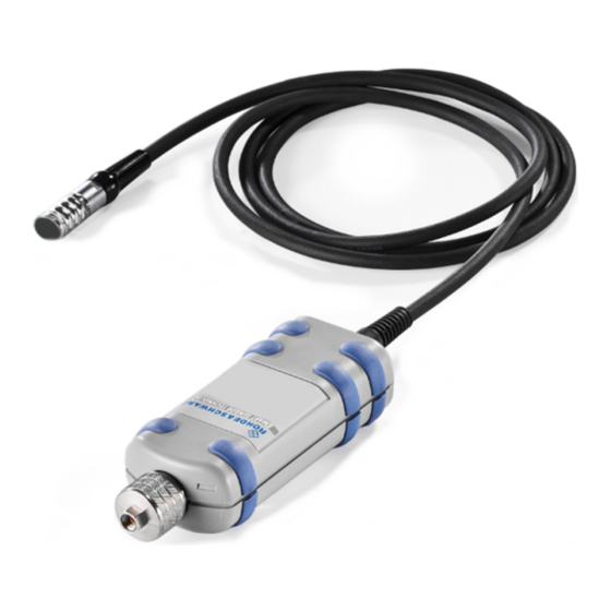
® Preparing for Use R&S NRP-Zxx Connectors of the R&S NRP‑Z Power Sensors EMI Suppression Electromagnetic interference (EMI) can affect the measurement results. To suppress generated electromagnetic interference: ● Use suitable shielded cables of high quality. For example, use double-shielded RF cables. - Page 13 ® Preparing for Use R&S NRP-Zxx Connectors of the R&S NRP‑Z Power Sensors ‑ Z power sensor Figure 4-1: Connectors of an R&S NRP 1 = Host connector 2 = RF connector Host connector See (1) in Figure 4-1. Lemo type host connector. You can plug it: ●...
-
Page 14: Connecting The R&S Nrp-Z Power Sensors
® Preparing for Use R&S NRP-Zxx Connecting the R&S NRP‑Z Power Sensors Used to connect the power sensor to a device under test (DUT) or a signal gener- ator. Caused by their different frequency ranges, the R&S NRP‑Z power sensors have different RF connectors. - Page 15 ® Preparing for Use R&S NRP-Zxx Connecting the R&S NRP‑Z Power Sensors 3. To ensure a maximal measurement accuracy, tighten the RF connector using a torque wrench with the recommended nominal torque (see the operating manual of your power sensor). 4.4.2 Connecting the Host Connector of the R&S NRP‑Z Power Sensors...
-
Page 16: Disconnecting The R&S Nrp-Z Power Sensors
® Preparing for Use R&S NRP-Zxx Disconnecting the R&S NRP‑Z Power Sensors To connect to an Rohde & Schwarz instrument ► Insert the host connector, red marking upwards, into the SENSOR connector of your instrument. Disconnecting the R&S NRP‑Z Power Sensors Additional requirements must be fulfilled when disconnecting the R&S NRP- Z27/-Z28/-Z37/-Z98 sensors. -
Page 17: Powering The R&S Nrp-Z Power Sensors
® Preparing for Use R&S NRP-Zxx Powering the R&S NRP‑Z Power Sensors To disconnect from an Rohde & Schwarz instrument or an R&S NRP‑Z5 sen- sor hub ► At the same time, press down the ring of the built-in plug (1) and pull off the cable sleeve (2). -
Page 18: Connecting To A Pc
® Connecting to a PC R&S NRP-Zxx Using a Passive USB Adapter Connecting to a PC There are different possibilities for connecting a power sensor to a PC, which can differ depending on the type of power sensor and available accessories. The following chapter gives an overview of the possible setups and what equip- ment is needed for each of them. -
Page 19: Using An Active Usb Adapter
® Connecting to a PC R&S NRP-Zxx Using an Active USB Adapter Incorrectly connecting/disconnecting the R&S NRP‑Z power sensors may damage the power sensors or lead to erroneous results. Ensure that you connect/disconnect your power sensors as described in Chapter 4.4, "Connecting the R&S NRP‑Z Power Sensors", on page 14 and Chapter 4.5, "Disconnecting the R&S NRP‑Z Power... - Page 20 ® Connecting to a PC R&S NRP-Zxx Using an Active USB Adapter Setup Figure 5-2: Setup with an active USB adapter 1 = Signal source 2 = R&S NRP‑Z power sensor 3 = R&S NRP‑Z3 4 = USB connector 5 = PC with a USB interface 6 = Trigger source (optional) 7 = BNC cable (optional, not supplied) 8 = Plug-in power supply (optional, supplied)
-
Page 21: Using An R&S Nrp-Z5 Sensor Hub
® Connecting to a PC R&S NRP-Zxx Using an R&S NRP‑Z5 Sensor Hub e) Connect the delivered plug-in power supply to the R&S NRP‑Z3 and to an AC supply connector (optional). 2. On the PC, start a software application to view the measurement results. See Chapter 6, "Operating Concepts", on page 24. - Page 22 ® Connecting to a PC R&S NRP-Zxx Using an R&S NRP‑Z5 Sensor Hub Setup ‑ Z5 sensor hub Figure 5-3: Setup with an R&S NRP = R&S NRP‑Z5 sensor hub = External power supply unit (supplied) = Power cable (supplied) = AC power supply = USB cable (supplied) = PC with USB host interface...
- Page 23 ® Connecting to a PC R&S NRP-Zxx Using an R&S NRP‑Z5 Sensor Hub = Triggered device (optional) 11-14 = R&S NRP‑Z power sensor = Signal source Incorrectly connecting/disconnecting the R&S NRP‑Z power sensors may damage the power sensors or lead to erroneous results. Ensure that you connect/disconnect your power sensors as described in Chapter 4.4, "Connecting the R&S NRP‑Z Power Sensors",...
-
Page 24: Operating Concepts
® Operating Concepts R&S NRP-Zxx R&S NRP Toolkit Operating Concepts For operating the power sensor, you can choose from various possibilities. Alternative to the methods of access described in this chapter, you can use remote control. For details, see: ● Chapter 7, "Remote Control", on page 37... - Page 25 ® Operating Concepts R&S NRP-Zxx R&S NRP Toolkit ● R&S NRP‑Z3 or R&S NRP‑Z4 USB adapter or R&S NRP‑Z5 sensor hub Supported operating systems: ● Microsoft Windows Vista 32/64-bit ● Microsoft Windows 7 32/64-bit ● Microsoft Windows 8 32/64-bit ● Microsoft Windows 10 32/64-bit ●...
- Page 26 ® Operating Concepts R&S NRP-Zxx R&S NRP Toolkit 2. In the "Choose Components" dialog, select the components you want to install and accept the license terms to continue with the installation 3. Click "Next" and complete the installation process. 6.1.3 Linux-Based Systems The R&S NRP Toolkit for a certain Linux distribution comes as a series of Debian (*.deb) or RPM (*.rpm) files.
- Page 27 ® Operating Concepts R&S NRP-Zxx R&S NRP Toolkit To install the R&S NRP Toolkit 1. In the Mac OS X Finder, double-click the provided .dmg disk image to mount 2. Double-click the NrpToolkit.mpkg installer to start the installation. The R&S NRP Toolkit installer opens. The welcome message gives an over- view of the packages that are part of the installer and indicates their default installation location.
- Page 28 ® Operating Concepts R&S NRP-Zxx R&S NRP Toolkit a) R&S NRP-Z Driver Framework (obligatory). b) Enable the "Power Viewer Plus application" (optional). c) Enable "Application Development" (optional). You can use these examples as starting points for your own implementations. 5. Click "Continue" and complete the installation process. After a successful installation, you can start the applications provided with the R&S NRP Toolkit from the Rohde-Schwarz folder that was created in the Mac OS X application directory.
-
Page 29: R&S Nrpv
® Operating Concepts R&S NRP-Zxx R&S NRPV 6.1.5 Performing a Firmware Update Use the firmware update program (PureFW) to load new firmware for the power sensors. It is part of the R&S NRP Toolkit that is supplied on a CD-ROM together with the power sensors. - Page 30 ® Operating Concepts R&S NRP-Zxx R&S NRPV 1 = Signal source 2 = R&S NRP‑Z power sensor 3 = R&S NRP‑Z4 4 = USB connector 5 = PC with installed R&S NRPV Incorrectly connecting/disconnecting the R&S NRP‑Z power sensors may damage the power sensors or lead to erroneous results.
-
Page 31: R&S Power Viewer
® Operating Concepts R&S NRP-Zxx R&S Power Viewer e) Confirm with "OK" to return to the "Licensing NRP-Z Power Sensors for NRPV" dialog. The dialog indicates all currently connected sensors. Note: If you want to evaluate the R&S NRPV before buying a license for your power sensor, you can activate a sensor for temporary use. -
Page 32: R&S Power Viewer Mobile
® Operating Concepts R&S NRP-Zxx R&S NRP2 For details on installing and operating the R&S Power Viewer, refer to its operat- ing manual. The manual is provided on the documentation CD-ROM and is instal- led automatically during the installation of the R&S Power Viewer. If you want to use an android device like a tablet or a smartphone, use the R&S Power Viewer Mobile. - Page 33 ® Operating Concepts R&S NRP-Zxx R&S NRP2 Setup Figure 6-2: Setup with an R&S NRP2 base unit 1 = Signal source 2 = R&S NRP‑Z power sensor 3 = SENSOR connector of the R&S NRP2 4 = R&S NRP2 base unit Incorrectly connecting/disconnecting the R&S NRP‑Z power sensors may damage the power sensors or lead to erroneous results.
-
Page 34: Compatible Instrument
® Operating Concepts R&S NRP-Zxx Compatible Instrument 5. If necessary, perform further settings. For a detailed description of how to measure in this setup, refer to the operating manual of your R&S NRP2. Compatible Instrument Many Rohde & Schwarz instruments allow power measurements using the R&S NRP‑Z power sensors. - Page 35 ® Operating Concepts R&S NRP-Zxx Compatible Instrument Setup Figure 6-3: Setup with an R&S SMF 1 = R&S SMF 2 = Device under test (DUT) 3 = R&S NRP‑Z icon 4 = [SENSOR] connector 5 = R&S NRP‑Z Power Sensors 6 = RF output of the DUT 7 = [RF OUT] connector of the R&S SMF 8 = RF input of the DUT...
- Page 36 ® Operating Concepts R&S NRP-Zxx Compatible Instrument The dialog shows the result (in dBm) and some additional parameters. 3. If necessary, perform further settings. For a detailed description of how to measure in this setup, refer to the operating manual your compatible Rohde & Schwarz instrument. Getting Started 1176.8822.02 ─...
-
Page 37: Remote Control
® Remote Control R&S NRP-Zxx Remote Control Use remote control to integrate the R&S NRP‑Z power sensors into custom auto- matic test equipment (ATE) systems. The latest version of the available instru- ment drivers is part of the R&S NRP Toolkit SDK under Windows. For a detailed description on how to perform different remote measurements, refer to various sample programs installed with the R&S NRP Toolkit SDK, or the ®... -
Page 38: Contacting Customer Support
® Contacting Customer Support R&S NRP-Zxx Contacting Customer Support Technical support – where and when you need it For quick, expert help with any Rohde & Schwarz product, contact our customer support center. A team of highly qualified engineers provides support and works with you to find a solution to your query on any aspect of the operation, program- ming or applications of Rohde &... -
Page 39: Index
® Index R&S NRP-Zxx Index Interface Overview ..........12 Android device Introduction ..........8 R&S Power Viewer Mobile ....32 Application cards ........7 Application notes ........7 Mobile measurements ......32 Brochures ..........7 Open source acknowledgment (OSA) ..7 Operating concepts ......... 24 App for Android devices ......32 Checking the delivery ...... - Page 40 ® Index R&S NRP-Zxx Security procedures ........6 Tutorials ............. 6 Unpacking the delivery ......12 USB connection .........18, 19 USB sensor hub ........21 User manual ..........6 White papers ..........7 Getting Started 1176.8822.02 ─ 04...
Need help?
Do you have a question about the NRP-Z00 and is the answer not in the manual?
Questions and answers