Table of Contents
Advertisement
Quick Links
Advertisement
Chapters
Table of Contents

Related Manuals for Rohde & Schwarz NRPM OTA Power Measurement Solution


Summary of Contents for Rohde & Schwarz NRPM OTA Power Measurement Solution
- Page 1 ® R&S NRPM OTA Power Measurement Solution Mannual (>IäÍ2) 1425866302 Version 08...
- Page 2 ® This document describes the R&S NRPM OTA Power Measurement Solution, including the following components: ● R&S ® NRPM3N Three-channel sensor module LAN, 1425.8592.02 ● R&S ® NRPM3 Three-channel sensor module, 1425.8563.02 ● R&S ® NRPM-A90 Single-polarized antenna module, 1426.7760.02/.03/.04/.05 ●...
-
Page 3: Table Of Contents
1.3 Warning messages in the documentation........11 2 Welcome to the R&S NRPM OTA power measurement sol- ution..................12 2.1 Key features..................12 2.2 About the R&S NRPM OTA power measurement solution....13 3 Documentation overview............ 15 3.1 User manual..................15 3.2 Tutorials....................15 3.3 Instrument security procedures............ - Page 4 ® Contents R&S NRPM 4.6 Installing the software application and drivers........23 4.6.1 VISA driver installation................24 4.6.2 R&S NRP Toolkit installation..............24 4.6.3 R&S Power Viewer installation..............27 5 R&S NRPM tour..............29 5.1 R&S NRPM3(N) sensor modules............29 5.2 R&S NRPM-A90 and R&S NRPM-A90D antenna modules....32 5.3 R&S NRPM-ZD3 feedthrough module..........
- Page 5 ® Contents R&S NRPM 8.1 Hardware and software requirements..........83 8.2 Updating the firmware................ 83 8.2.1 Using the firmware update for R&S NRP family program..... 84 8.2.2 Using the web browser-based user interface........86 8.2.3 Using remote control................87 9 Network and remote operation...........89 9.1 Remote control interfaces and protocols.........89 9.1.1 USB interface..................90 9.1.2 Ethernet interface..................91...
- Page 6 10.11.4 Controlling the ENABle part..............182 10.11.5 Controlling the negative transition part..........183 10.11.6 Controlling the positive transition part..........184 10.12 Testing the R&S NRPM OTA Power Measurement Solution..184 10.13 Calibrating/zeroing the R&S NRPM3(N) sensor module....185 11 Programming examples............ 187 11.1 Performing a simple measurement..........
- Page 7 ® Contents R&S NRPM 11.2 Performing measurements in continuous average mode.....187 11.3 Performing measurements in list mode......... 192 11.4 Performing measurements in trace mode........199 12 Troubleshooting..............203 12.1 Displaying status information............203 12.2 Performing a selftest................ 203 12.3 Problems during a firmware update..........204 12.4 Cannot establish a LAN connection..........
- Page 8 ® Contents R&S NRPM Mannual 1425.8663.02 ─ 08...
-
Page 9: Safety And Regulatory Information
The target audience is developers and technicians. The required skills and expe- rience in power measurements depend on the used operating concept. The R&S NRPM OTA power measurement solution is designed for use in anechoic environments as RF shielded boxes or benchtop applications in RF test chambers. -
Page 10: Labels On The Product
® Safety and regulatory information R&S NRPM Labels on the product the instructions provided here and in the product documentation. Keep the prod- uct documentation nearby and offer it to other users. Use the product only for its intended use and within its performance limits. Inten- ded use and limits are described in the product documentation such as the data sheet, manuals and the printed "Safety Instructions". -
Page 11: Warning Messages In The Documentation
® Safety and regulatory information R&S NRPM Warning messages in the documentation ● Identification of the product Chapter 6.3.5.1, "Using hostnames", on page 55. ● Sensitive components Table 1-2 Table 1-1: Labels regarding environment safety Labeling in line with EN 50419 for disposal of electrical and electronic equipment after the product has come to the end of its service life. -
Page 12: Welcome To The R&S Nrpm Ota Power Measurement Solution
Introduces the R&S NRPM OTA power measurement solution. Key features The R&S NRPM OTA power measurement solution is designed to calibrate the transmit antenna output power and test the beamforming function over the air. Applications are in high frequency bands, used in modern high performance wire- less system standards, e.g. -
Page 13: About The R&S Nrpm Ota Power Measurement Solution
® Welcome to the R&S NRPM OTA power measurement solution R&S NRPM About the R&S NRPM OTA power measurement solution About the R&S NRPM OTA power measurement solution The power measurement solution consists of antenna modules, a three-channel sensor module, and interface modules for connecting the antenna modules to the sensor module. - Page 14 ® Welcome to the R&S NRPM OTA power measurement solution R&S NRPM About the R&S NRPM OTA power measurement solution For communication over the USB with the standardized protocol USBTMC, the drivers and APIs are provided for the operating systems Linux, Mac OS X, MS Windows.
-
Page 15: Documentation Overview
® Documentation overview R&S NRPM Basic safety instructions Documentation overview This section provides an overview of the R&S NRPM user documentation. Unless specified otherwise, you find the latest versions of the documents on the product page at: www.rohde-schwarz.com/manual/nrpm. User manual Introduces the R&S NRPM and describes how to set up and start working with the product. -
Page 16: Data Sheets And Brochures
® Documentation overview R&S NRPM Release notes and open source acknowledgment (OSA) Data sheets and brochures The data sheet contains the technical specifications of the R&S NRPM OTA power measurement solution. It also lists the options and their order numbers and optional accessories. -
Page 17: Preparing For Use
® Preparing for use R&S NRPM Choosing the operating site Preparing for use Here, you can find basic information about setting up the product for the first time. ● Unpacking and checking................. 17 ● Choosing the operating site................17 ● Considerations for test setup................ -
Page 18: Considerations For Test Setup
Considerations for test setup Give particular attention to the following aspects when handling the components of the R&S NRPM OTA power measurement solution. For information on the options for connecting the sensor modules and test setups for the measurements, see Chapter 6, "Setting up a... - Page 19 ® Preparing for use R&S NRPM Considerations for test setup EMI impact on measurement results Electromagnetic interference (EMI) can affect the measurement results. To suppress electromagnetic radiation during operation: ● Use high-quality shielded cables, for example, double-shielded RF and inter- face cables.
-
Page 20: Powering The R&S Nrpm3(N) Sensor Module
® Preparing for use R&S NRPM Hardware and software requirements Powering the R&S NRPM3(N) sensor module The electrical power for a R&S NRPM3(N) sensor module is supplied over one of the following interfaces: ● Host interface "Host interface connector (3)" on page 30. -
Page 21: Mandatory Software
® Preparing for use R&S NRPM Hardware and software requirements – R&S NRPM-A90D: occupies two channels of the sensor module. You can split the antenna module cables of one R&S NRPM-A90D antenna module on two interface or feedthrough modules. ● One of the following: –... -
Page 22: Optional Software
® Preparing for use R&S NRPM Hardware and software requirements R&S VISA allows fast communication with the sensor module. It includes a trace tool for communication analysis, a testing tool for connection check, and a configuration tool for the definition of resources. ●... -
Page 23: Installing The Software Application And Drivers
® Preparing for use R&S NRPM Installing the software application and drivers Table 4-2, which shows where you can get the packages for the corre- sponding OS. Table 4-2: Information to GUI application R&S Power Viewer and programming examples R&S Power Viewer Programming examples MS Windows Available on the Internet, see... -
Page 24: Visa Driver Installation
® Preparing for use R&S NRPM Installing the software application and drivers 4.6.1 VISA driver installation To install the R&S VISA standardized software library on MS Windows: ► Consult the Rohde & Schwarz www.rohde-schwarz.com/rsvisa web site, that provides the software and the necessary information. If you are using VISA from another supplier, refer to the corresponding docu- mentation on how to install the driver on your system. - Page 25 ® Preparing for use R&S NRPM Installing the software application and drivers A dialog similar to the following appears. 3. In the main dialog: a) Select the R&S NRP Toolkit 64-bit option if your MS Windows PC has 64- bit architecture. The 32-bit version is always installed. b) To include the programming examples, select "NRP-Toolkit SDK".
- Page 26 ® Preparing for use R&S NRPM Installing the software application and drivers To install the R&S NRP Toolkit on Linux R&S NRP Toolkit versions for Linux distributions are available on request. Rohde & Schwarz provides installation packages for many popular distributions like Debian, CentOS, Ubuntu, OpenSuse, Raspbian, and others, in various ver- sions.
-
Page 27: R&S Power Viewer Installation
® Preparing for use R&S NRPM Installing the software application and drivers To install the R&S NRP Toolkit on macOS Rohde & Schwarz provides a macOS NRP-Toolkit installer. The macOS version differs from the Linux and Windows NRP-Toolkit in the way that it includes a ver- sion of the R&S Power Viewer application. - Page 28 ® Preparing for use R&S NRPM Installing the software application and drivers To install the R&S Power Viewer on Linux The R&S Power Viewer for Linux comes as a self-extracting installation package (*.run file). Follow these steps to install the application in your Linux system: 1.
-
Page 29: S Nrpm Tour
R&S NRPM3(N) sensor modules R&S NRPM tour The following chapters introduce the main hardware components of the R&S NRPM OTA power measurement solution. R&S NRPM3(N) sensor modules The R&S NRPM3(N) three-channel sensor module processes the measured val- ues from up to three antenna modules in three separate channels. - Page 30 ® R&S NRPM tour R&S NRPM R&S NRPM3(N) sensor modules Antenna connector (1) Multipole antenna connector for connecting the ● R&S NRPM3(N) to the interface module R&S NRPM-Z3. ● R&S NRPM3(N) to the filtered cable feedthrough module R&S NRPM-ZD3 with the interface cable R&S NRPM-ZKD3. Note: Measurements with R&S NRPM3N LAN sensor modules require that you use the latest version of the R&S NRPM-ZKD3 interface cable (1436.2984.02).
- Page 31 ® R&S NRPM tour R&S NRPM R&S NRPM3(N) sensor modules For information on how to assign the signals to the ports, see Chapter 10.10, "Configuring the trigger", on page 172. Trigger I/O connector (4) The trigger I/O is a connector of SMB type. You can use this interface as an input for an external trigger signal.
-
Page 32: R&S Nrpm-A90 And R&S Nrpm-A90D Antenna Modules
® R&S NRPM tour R&S NRPM R&S NRPM-A90 and R&S NRPM-A90D antenna modules Indication State Green The interface provides PoE. The sensor module is powered. Not illuminated PoE power is not applied. R&S NRPM-A90 and R&S NRPM-A90D antenna modules This section introduces the antenna modules of the R&S NRPM OTA power mea- surement solution. - Page 33 ® R&S NRPM tour R&S NRPM R&S NRPM-A90 and R&S NRPM-A90D antenna modules R&S NRPM-A90D Dual polarized antenna module with integrated diode detectors 1 = PCBs (printed circuit boards) To distinguish the feeds, the carrier of the R&S NRPM-A90D antenna module is labeled 2 = Interface cables on the back with the corresponding letters "1"...
-
Page 34: R&S Nrpm-Zd3 Feedthrough Module
® R&S NRPM tour R&S NRPM R&S NRPM-ZD3 feedthrough module Signaling LED (3) LED for signaling purposes. You can use the LED for mapping between the antenna module location and the sensor module channel, or for own signaling purposes. To turn on the LED, use the SCPI command SYSTem:LED: on page 130. - Page 35 ® R&S NRPM tour R&S NRPM R&S NRPM-ZD3 feedthrough module Figure 5-2: The R&S NRPM-ZD3 feedthrough module 1 = Antenna module cable connectors 2 = Cable feedthrough module 3 = Sensor module cable connector Antenna module cable connectors (1) Micro miniature connectors (10 pin) for connecting up to three antenna module cables.
-
Page 36: R&S Nrpm-Z3 Interface Module
® R&S NRPM tour R&S NRPM R&S NRPM-Z3 interface module R&S NRPM-Z3 interface module For direct connection inside an EM controlled environment, you can use the R&S NRPM-Z3 interface module. Plugged directly to the R&S NRPM3(N) three channel sensor module, the R&S NRPM-Z3 interface module can host up to three antenna modules without additional cables required. -
Page 37: R&S Nrpm-Z3 Connected To The R&S Nrpm3
® R&S NRPM tour R&S NRPM R&S NRPM-Z3 connected to the R&S NRPM3 R&S NRPM-Z3 connected to the R&S NRPM3 Figure 5-4: R&S NRPM-Z3 connected to R&S NRPM3 1 = R&S NRP-ZKU 2 = R&S NRPM3 3 = R&S NRPM-Z3 4 = Strain relieve 5 = Antenna module cables Strain relieve (4) -
Page 38: Setting Up A Measurement
® Setting up a measurement R&S NRPM Test setup examples Setting up a measurement This section points out important aspects to consider when setting up an R&S NRPM OTA power measurement. It shows some test setup examples and brief instructions on how to connect the components. You can also find referen- ces to the product page and the user manual of the RF shielded box R&S CMQ200 or an RF test chamber. - Page 39 ® Setting up a measurement R&S NRPM Test setup examples Test setups with R&S NRPM3N LAN sensor modules and the R&S NRPM- ZKD3 interface cables for connection to a RF shielded box, require that you use the latest version of the interface cable (1436.2984.02). Single antenna module solution The base configuration with one antenna module measures the power of the inci- dent wave from the DUT to the antenna module, e.g.
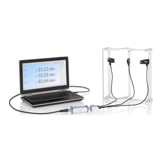
- Page 40 ® Setting up a measurement R&S NRPM Test setup examples Example: Setup with multiple single polarized R&S NRPM-A90 antenna modules in an RF shielded box (feedthrough modules): Figure 6-2: Multiple R&S NRPM-A90 in an RF shielded box 1 = Controller PC 2 = Sensor modules 3 = RF shielded box Mannual 1425.8663.02 ─...
- Page 41 ® Setting up a measurement R&S NRPM Test setup examples Example: Setup with multiple single polarized R&S NRPM-A90 antenna modules in an RF test chamber (interface modules): Figure 6-3: Multiple R&S NRPM-A90 in an RF test chamber 1 = Controller PC 2 = Sensor modules 3 = RF test chamber Mannual 1425.8663.02 ─...
-
Page 42: R&S Cmq200 Shielding Cube
® Setting up a measurement R&S NRPM R&S CMQ200 shielding cube Example: Setup with dual polarized R&S NRPM-A90D antenna modules in an RF shielded box with feedthrough modules: Figure 6-4: Setup with multiple R&S NRPM-A90D in an RF shielded box 1 = Controller PC 2 = Sensor modules 3 = RF shielded box... -
Page 43: Connecting An R&S Nrpm Ota Power Measurement
® Setting up a measurement R&S NRPM Connecting an R&S NRPM OTA power measurement As the R&S CMQ200 is a stand-alone product of Rohde & Schwarz, this section does not describe the box and measurement setups in detail. If you perform an OTA measurement with the box, you find the necessary information at: ●... -
Page 44: Connecting The Rf Frontend
® Setting up a measurement R&S NRPM Connecting an R&S NRPM OTA power measurement 6.3.1 Connecting the RF frontend The following steps describe how to connect the antenna modules and a sensor module in both, an RF shielded box or an RF test chamber. 6.3.1.1 Connecting the RF frontend in an RF shielded box When you are working with the dual-polarized antenna modules... - Page 45 ® Setting up a measurement R&S NRPM Connecting an R&S NRPM OTA power measurement Connect each antenna module cable to the antenna module cable connectors of the feedthrough module R&S NRPM-ZD3 (2). 4. Outside the RF shielded box, make sure that the sensor module is powered off, i.e.
-
Page 46: Connecting To The Controller Pc
Take care not to tilt it. 6.3.2 Connecting to the controller PC The controlling host of the R&S NRPM OTA power measurement solution is a computer, using a supported software for controlling the R&S NRPM3(N) sensor modules, see Chapter 4.5, "Hardware and software... -
Page 47: Using The Usb Connection
® Setting up a measurement R&S NRPM Connecting an R&S NRPM OTA power measurement You can connect the sensor module using the LAN interface, when working with the R&S NRPM3N. To connect the R&S NRPM3, use the USB host interface. To connect the sensor module to the controller PC, see: ●... - Page 48 ® Setting up a measurement R&S NRPM Connecting an R&S NRPM OTA power measurement 1 = Controller PC 2 = R&S NRP-ZKU 3 = USB host interface connector 4 = R&S NRPM3 sensor module 5 = Antenna connector 6 = Antenna module(s) To connect the R&S NRPM3 sensor module and the controller PC Setup as shown in Figure...
- Page 49 ® Setting up a measurement R&S NRPM Connecting an R&S NRPM OTA power measurement Setup ‑ Z5 sensor hub Figure 6-6: Setup with an R&S NRP 1 = Controller PC 2 = USB cable 3 = R&S NRP‑Z5 sensor hub 4 = NRP-ZK6 cables 5 = USB host interface connector 6 = R&S NRPM3 sensor module...
-
Page 50: Using The Lan Connection
® Setting up a measurement R&S NRPM Connecting an R&S NRPM OTA power measurement 7. On the computer, start a software application to execute the measurement, Chapter 7, "Performing measurements", on page 58. 6.3.4 Using the LAN connection Requires the R&S NRPM3N LAN sensor module with networking capabili- ties. - Page 51 ® Setting up a measurement R&S NRPM Connecting an R&S NRPM OTA power measurement = Controller PC 2, 4 = RJ-45 Ethernet cables = Ethernet switch = LAN connector (RJ-45 Ethernet PoE interface) = R&S NRPM3N LAN sensor module = Antenna connector = Antenna module(s) To connect the R&S NRPM3N to the controller PC with the PoE Ethernet switch...
- Page 52 ® Setting up a measurement R&S NRPM Connecting an R&S NRPM OTA power measurement Setup Figure 6-8: Setup with a PoE injector and a non-PoE Ethernet switch = Controller PC 2,4,6 = RJ-45 Ethernet cables = Non-PoE Ethernet switch = PoE injector = LAN connector (RJ-45 Ethernet PoE interface) = R&S NRPM3N LAN sensor module = Antenna connector...
- Page 53 ® Setting up a measurement R&S NRPM Connecting an R&S NRPM OTA power measurement To avoid any impact, use at least category 6 STP cables for the LAN connec- tion, see Chapter 4.5.1, "Hardware", on page 20. ● 1 PoE injector ●...
-
Page 54: Connecting To The Network
® Setting up a measurement R&S NRPM Connecting an R&S NRPM OTA power measurement 6.3.5 Connecting to the network There are two methods to establish a network connection: ● The R&S NRPM3N LAN sensor module and controlling host are connected to a common network (infrastructure network). - Page 55 ® Setting up a measurement R&S NRPM Connecting an R&S NRPM OTA power measurement nrpm3n-101441 nrpm3n-101441.local 6.3.5.1 Using hostnames In a LAN that uses a domain name system (DNS) server, each connected com- puter or instrument can be accessed via an unambiguous hostname instead of an IP address.
- Page 56 ® Setting up a measurement R&S NRPM Connecting an R&S NRPM OTA power measurement For establishing a connection to the sensor module, try the default hostname and the hostname extended with .local as shown in the example below. All commu- nication for resolving names in the top-level-domain (TLD) .local are defined to be executed using dedicated local services and ports if no other DNS (domain name server) is available.
-
Page 57: Starting The Measurement
® Setting up a measurement R&S NRPM Starting the measurement Starting the measurement To start the measurement To start an R&S NRPM OTA power measurement, it is assumed that all compo- nents of the test setup are connected. An easy way for configuring the measurement and displaying results is given by the R&S Power Viewer software: ►... -
Page 58: Performing Measurements
® Performing measurements R&S NRPM Measurement applications Performing measurements Sensor module readings The antenna modules R&S NRPM-A90 and R&S NRPM-A90D have an integra- ted diode detector each that converts the RF signal and transmits it directly to the sensor module. You can measure the power of the incident electromagnetic wave towards the antenna module in various quantities: ●... -
Page 59: Using R&S Power Viewer
® Performing measurements R&S NRPM Measurement applications The following sections introduce the power measurement with the R&S Power Viewer and the WebGUI (web browser-based user interface). Section Chapter 11, "Programming examples", on page 187 describes the corresponding programming examples for working in remote control mode. See the R&S Power Viewer manual for more information on how to use the various func- tions of the application. - Page 60 ® Performing measurements R&S NRPM Measurement applications Outlined are: ● To start the application. ● To configure an OTA single sensor ContAV measurement, for using the R&S NRPM3(N) with up to three antenna modules. ● To configure an OTA multi sensor ContAV measurement, for using of up to four sensor modules with up to three antenna modules each.
- Page 61 ® Performing measurements R&S NRPM Measurement applications 2. In the lower border toolbar, select the sensor module. 3. Execute zeroing: Note: Turn off all measurement power signals before zeroing. An active mea- surement during zeroing causes an error. a) Turn off the measurement signal. b) Select "Sensor >...
- Page 62 ® Performing measurements R&S NRPM Measurement applications The measurement results window displays measured power in the sensor module channels. To configure an OTA multi sensor ContAV measurement In the toolbar, select the "OTA Multi Sensor" button to open the panel for the OTA measurements with several sensor modules.
- Page 63 ® Performing measurements R&S NRPM Measurement applications 2. In the lower border toolbar, select the sensor module. 3. In the panel on the right, select the channel. 4. Enable the antenna modules of the selected channel. 5. If necessary, set the parameters provided for the measurement mode. 6.
- Page 64 ® Performing measurements R&S NRPM Measurement applications The measurement results window displays the results of the multi channel measurement. To configure an OTA single sensor trace power measurement In the toolbar, select the button to open the panel for trace measurements. Mannual 1425.8663.02 ─...
- Page 65 ® Performing measurements R&S NRPM Measurement applications The R&S Power Viewer displays the trace measurement results windows, and the setting parameters in the panel on the right. 2. In the lower border toolbar, select the sensor module. 3. In the panel on the right, select the antenna modules for the measurement. 4.
-
Page 66: Using The Web Browser-Based User Interface
® Performing measurements R&S NRPM Measurement applications The results window displays the trace measurement results of the three antenna modules. 7.2.2 Using the web browser-based user interface Requires a sensor module with networking capabilities, a R&S NRPM3N sensor module. The web browser-based user interface is an alternative way to operate an R&S NRPM3N LAN sensor module. - Page 67 ® Performing measurements R&S NRPM Measurement applications ● Safari 5.1 or later You can use the web browser-based user interface with all devices and operating systems, including tablets and smart phones that are connected to the same net- work. Starting a measurement 1.
-
Page 68: Main Dialog Of The Web Browser-Based User Interface
® Performing measurements R&S NRPM Measurement applications The following chapters describe the functions and parameters of the web browser-based user interface in detail. ● Main dialog of the web browser-based user interface........68 ● Setting the unit....................69 ● Common settings.................... 70 ●... -
Page 69: Setting The Unit
® Performing measurements R&S NRPM Measurement applications The parameters pane provides the setting parameters for the corresponding func- tion selected in the navigation pane. The result pane displays the measurement readings either numerically or graphi- cally, depending on the selected measurement mode. 7.2.2.2 Setting the unit You can set the unit for the different parameters by typing the corresponding letter... -
Page 70: Common Settings
® Performing measurements R&S NRPM Measurement applications Unit multiples Keyboard key micro nano Example: To set the unit to 1 GHz, enter 1g. For certain units, you can select a different representation, depending on the requirements. For example, for the representation of the "Trigger Level", you can choose Watt, dBm or dBµV. - Page 71 ® Performing measurements R&S NRPM Measurement applications System Status.......................71 Measurement......................71 Frequency......................71 Offset........................71 └ <State>...................... 71 └ <Value>......................71 S-Parameter......................72 Averaging......................72 System Status Displayed in the title bar. Confirms that there is a connection between the sensor and the remote computer and that the sensor is recognized by the software. The presentation of this symbolic LED mirrors the physical LED of the sensor, see "Status LED (2)"...
-
Page 72: Measurement Modes
® Performing measurements R&S NRPM Measurement applications S-Parameter Note: S-parameter compensation is not supported by the R&S NRPM3 sensor modules. Averaging Chapter 10.8.1, "Configuring averaging", on page 165. 7.2.2.4 Measurement modes Provides the parameters for the supported measurement modes. ● Continuous Average mode................72 ●... - Page 73 ® Performing measurements R&S NRPM Measurement applications Duty Cycle Sets the duty cycle, the percentage of one period during which the signal is active, for pulse modulated signals. If activated, the sensor calculates the signal pulse power from its value and the average power. Remote command: on page 169 [SENSe<Sensor>:]CORRection:DCYCle:STATe...
-
Page 74: Settings
® Performing measurements R&S NRPM Measurement applications Trace Offset Time Sets the relative position of the trigger event in relation to the beginning of the trace measurement sequence. Used to specify the start of recording for the trace mode. Remote command: on page 163 [SENSe<Sensor>:]TRACe:OFFSet:TIME Trace Points... - Page 75 ® Performing measurements R&S NRPM Measurement applications The remote commands required to define the sensor settings are described ● Chapter 10.4.2, "Handling of available antenna modules", on page 134 ● Chapter 10.8.3, "Configuring corrections", on page 168 ● Chapter 10.13, "Calibrating/zeroing the R&S NRPM3(N) sensor module", on page 185 ●...
- Page 76 ® Performing measurements R&S NRPM Measurement applications Averaging settings Describes the parameters for automatic averaging. Access: ► In the settings navigation pane of the web browser-based user interface, select "Averaging". The remote commands required to define the averaging settings are descri- bed in Chapter 10.8.1, "Configuring averaging",...
- Page 77 ® Performing measurements R&S NRPM Measurement applications Averaging Mode Indicates that the R&S NRPM3N works in manual averaging mode and enables you to set the average count, also considered as averaging factor. Chapter 10.8.1, "Configuring averaging", on page 165. <Mode> ← Averaging Mode Displays the averaging mode.
- Page 78 ® Performing measurements R&S NRPM Measurement applications Access: ► In the settings navigation pane of the web browser-based user interface, select "Trigger". The remote commands required to define the trigger settings are described in: ● Chapter 10.10, "Configuring the trigger", on page 172 ●...
-
Page 79: System Settings
® Performing measurements R&S NRPM Measurement applications Trigger Level Sets the trigger threshold for internal triggering derived from the test signal. Remote command: on page 176 TRIGger:LEVel on page 177 TRIGger:LEVel:UNIT Trigger Delay Sets the delay between the trigger event and the actual start of the measurement. Remote command: on page 174 TRIGger:DELay... - Page 80 ® Performing measurements R&S NRPM Measurement applications Access: ► In the settings navigation pane of the web browser-based user interface, select "System". The remote commands required to define the system settings are described in Chapter 10.4.1, "Configuring the system", on page 120. Address......................
- Page 81 ® Performing measurements R&S NRPM Measurement applications DHCP Selects the mode for assigning the IP address. "Auto" Assigns the IP address automatically, provided the network sup- ports DHCP (dynamic host configuration protocol). "Static" Enables you to assign the IP address manually. Remote command: on page 122 SYSTem:COMMunicate:NETWork:IPADdress:MODE...
- Page 82 ® Performing measurements R&S NRPM Measurement applications When completed, the web browser-based user interface displays a report with the test results. Remote command: on page 184 TEST:SENSor? Mannual 1425.8663.02 ─ 08...
-
Page 83: Firmware Update
® Firmware update R&S NRPM Updating the firmware Firmware update ● Hardware and software requirements............. 83 ● Updating the firmware..................83 Hardware and software requirements To perform a firmware update, you need: ● Connectors and cables for establishing a connection to the PC, see Chap- ter 6.3.2, "Connecting to the controller PC",... - Page 84 ® Firmware update R&S NRPM Updating the firmware ● Using the firmware update for R&S NRP family program....... 84 ● Using the web browser-based user interface..........86 ● Using remote control..................87 8.2.1 Using the firmware update for R&S NRP family program The Firmware update for R&S NRP family program is part of the R&S NRP Tool- kit, see Chapter 4.6.2, "R&S NRP Toolkit...
- Page 85 ® Firmware update R&S NRPM Updating the firmware 3. If the sensor module you want to update is not listed, perform one of the fol- lowing actions: a) Make sure the sensor module is physically connected. b) Select "Rescan". This function starts a new search for sensor modules. c) Check whether all necessary drivers are installed on the computer.
- Page 86 ® Firmware update R&S NRPM Updating the firmware Troubleshooting R&S NRPM3N LAN sensor module not detected You do not find the sensor module in the list of sensor modules provided by firm- ware update for R&S NRP family. The driver assigned to the sensor module is the legacy driver. ►...
- Page 87 ® Firmware update R&S NRPM Updating the firmware 3. In the navigation pane, select "System". 4. Select "Firmware Update". 5. In the "Firmware Update" dialog, select "Select RSU file". 6. In the file browser, select the *.rsu file for upload. The dialog displays the selected file with file size and status.
- Page 88 ® Firmware update R&S NRPM Updating the firmware The size of the file is 10242884. This number has 8 digits. Thus, the <block_data> consist of the following: ● # ● 8 How many digits follow to specify the file size. ●...
- Page 89 ® Network and remote operation R&S NRPM Remote control interfaces and protocols Network and remote operation In addition to controlling an R&S NRPM3(N) sensor module on a PC application, you can operate and control it with an application that supports direct remote con- trol from a remote PC.
- Page 90 ® Network and remote operation R&S NRPM Remote control interfaces and protocols Table 9-1: Remote control interfaces and protocols Interface Supported by Protocols, VISA address string and library R&S NRPM3 USBTMC R&S NRPM3N USB::<vendor ID>::<product ID>:: <serial number>[::INSTR] VISA ● Ethernet R&S NRPM3N VXI-11...
- Page 91 ® Network and remote operation R&S NRPM Remote control interfaces and protocols The syntax of the used USB resource string is: USB::<vendor ID>::<product ID>::<serial number>[::INSTR] Where: ● <vendor ID> is the vendor ID for Rohde & Schwarz (0x0AAD). ● <product ID> is the product ID for the Rohde & Schwarz sensor module. ●...
- Page 92 ® Network and remote operation R&S NRPM Remote control interfaces and protocols unique identifier, composed of the specific IP address of the sensor module and some network and VISA-specific keywords. TCPIP::<IP address or hostname>[::<LAN device name>][::INSTR] ● TCPIP designates the network protocol used ●...
- Page 93 ® Network and remote operation R&S NRPM Remote control interfaces and protocols Socket communication TCPIP::<IP address or hostname>::port::SOCKET ● port determines the used port number ● SOCKET indicates the raw network socket resource class Socket communication requires the specification of the port (commonly referred to as port number) and of "SOCKET"...
- Page 94 ® Network and remote operation R&S NRPM Remote control interfaces and protocols uses two TCP sockets for a single connection - the first for fast data transfer, the second one for non-sequential control commands (e.g. Device Clear or SRQ). HiSLIP has the following characteristics: ●...
- Page 95 ® Network and remote operation R&S NRPM Status reporting system Status reporting system The status reporting system stores all information on the current operating state of the sensor module, and on errors which have occurred. This information is stored in the status registers and in the error queue. You can query both with the commands of the STATus subsystem.
- Page 96 ® Network and remote operation R&S NRPM Status reporting system Device Sensor Error Summary Status Sensor Error Sensor Error Sensor Error Sensor Error Legacy Locked Reference-PLL Locked Questionable Output-Queue Status Power Summary Calibration Summary POST Failure Error-/Event-Queue Standard Operation Complete Event Query Error Status...
- Page 97 ® Network and remote operation R&S NRPM Status reporting system The highest level is formed by the status byte register (STB) and the associated service request enable (SRE) register. The STB receives its information from the standard event status register (ESR) and the associated Standard Event Status Enable (ESE) Register, as well as from the SCPI-defined operation status register, and the questionable status register, which contain detailed information on the device, and from the device status reg-...
- Page 98 ® Network and remote operation R&S NRPM Status reporting system part can only be read, but not written into or cleared. Its contents are not affected by reading. PTRansition / NTRansition status register part The two transition register parts define which state transition of the CONDition part (none, 0 to 1, 1 to 0 or both) is stored in the EVENt part.
- Page 99 ® Network and remote operation R&S NRPM Status reporting system ENABle bit = 1: if the associated EVENt bit is "1", the sum bit is set to "1" as well. This part can be written into and read by the user as required. Its contents are not affected by reading.
- Page 100 ® Network and remote operation R&S NRPM Status reporting system Bit No. Meaning Error queue not empty The bit is set if the error queue has an entry. If this bit is enabled by the SRE, each entry of the error queue generates a service request. An error can thus be recognized and specified in detail by querying the error queue.
- Page 101 ® Network and remote operation R&S NRPM Status reporting system PPE; bit 6 is also used - in contrast to the SRE. The IST flag is obtained by ORing all results together. The PPE can be set by the *PRE command and read by the *PRE? query. 9.2.5 Device status register Contains information on the state of the static errors.
- Page 102 ® Network and remote operation R&S NRPM Status reporting system Bit No. Meaning Reference PLL locked state This bit signals whether the PLL for the clock reference is synchronized. The bit is useful when selecting an external clock source. The following states are possible: ●...
- Page 103 ® Network and remote operation R&S NRPM Status reporting system Table 9-5: Meaning of bits used in the questionable status register Bit No. Meaning 0 to 2 Not used Questionable power status register summary bit Corresponds to the summary bit of the questionable power status register. Chapter 9.2.6.1, "Questionable power status register", on page 103.
- Page 104 ® Network and remote operation R&S NRPM Status reporting system 9.2.6.2 Questionable calibration status register The EVENt register and the CONDition register contain information whether the zero offset of a sensor module is still valid. Querying the register: ● STATus:QUEStionable:CALibration:CONDition? ●...
- Page 105 ® Network and remote operation R&S NRPM Status reporting system Bit No. Meaning Execution error This bit is set if the syntax of a received command is correct but the command cannot be executed due to various marginal conditions. An error message with a number between -200 and -300 denoting the error in greater detail is entered in the error queue.
- Page 106 ® Network and remote operation R&S NRPM Status reporting system Bit No. Meaning 7 to 9 Not used Sense status register summary bit This bit is set if a sensor module is initialized. Chapter 9.2.8.4, "Operation sense status register", on page 109. Lower limit fail status register This bit is set if a displayed value has dropped below a lower limit value.
- Page 107 ® Network and remote operation R&S NRPM Status reporting system Mannual 1425.8663.02 ─ 08...
- Page 108 ® Network and remote operation R&S NRPM Status reporting system 9.2.8.1 Operation calibrating status register The CONDition register contains information about whether a sensor module is currently being calibrated and, depending on the configuration of the transition register. The EVENt register indicates whether a calibration was started or com- pleted since the last readout of this register.
- Page 109 ® Network and remote operation R&S NRPM Status reporting system 9.2.8.3 Operation trigger status register The CONDition register contains information about whether a sensor module is currently in the waiting for trigger state, i.e. expecting a trigger event and, depending on the configuration of the transition register. The EVENt register indi- cates whether the waiting for trigger state was entered or quit by a sensor module since the last readout of the register.
- Page 110 ® Network and remote operation R&S NRPM Status reporting system Table 9-13: Meaning of bits used in the operation sense status register Bit No. Meaning Not used sensor module initializing The sensor module is being initialized. 5 to 15 Not used 9.2.8.5 Operation lower limit fail status register The CONDition register contains information about whether a displayed value is...
- Page 111 ® Network and remote operation R&S NRPM Status reporting system Table 9-15: Meaning of bits used in the operation lower limit fail status register Bit No. Meaning Not used Upper limit fail The measured value exceeds the upper limit value. 5 to 15 Not used Mannual 1425.8663.02 ─...
- Page 112 ® Remote control commands R&S NRPM Conventions used in SCPI command descriptions Remote control commands In the following sections, all commands implemented in the sensor are listed according to the command system and then described in detail. Mostly, the nota- tion used complies with SCPI specifications.
- Page 113 ® Remote control commands R&S NRPM Notations Table 10-1: Units Basic Also noted as unit Frequency Seconds Watts degrees Angle Percent dBuV DBUV 10.2 Notations For a detailed description of SCPI notations, see Remote control via SCPI. Numeric suffixes <n> If a command can be applied to multiple instances of an object, e.g.
- Page 114 ® Remote control commands R&S NRPM Common commands Example: Command [SENSe<Sensor>:][POWer:][AVG:]SMOothing:STATe 1 can be written as: SENSe1:POWer:AVG:SMOothing:STATe 1 SENS:POW:AVG:SMO:STAT 1 SENSe:POWer:SMOothing:STATe 1 SENSe:SMOothing:STATe 1 SMOothing:STATe 1 SMO:STAT 1 Parameters Parameters must be separated from the header by a "white space". If several parameters are specified in a command, they are separated by a comma (,).
-
Page 115: Cls
® Remote control commands R&S NRPM Common commands Remote Commands: ........................115 *CLS ........................115 *ESE ........................116 *ESR? ........................116 *IDN? ........................116 *IST? ........................116 *OPC ........................117 *OPT? ........................117 *PRE ........................117 *RCL ........................118 *RST ........................118 *SAV ........................118 *SRE ........................ -
Page 116: Esr
® Remote control commands R&S NRPM Common commands Parameters: <register> Range: 0 to 255 *RST: *ESR? Event Status Read query Returns the contents of the event status register in decimal form (0 to 255) and subsequently sets the register to zero. Usage: Query only *IDN? -
Page 117: Opt
® Remote control commands R&S NRPM Common commands Since *OPC? waits until all previous commands are executed, "1" is returned in all cases. *OPC? basically functions like the command, but does not return a *WAI *WAI response. *OPC? is preferred to because with *OPC?, the execution of commands can *WAI be queried from a controller program before new commands are sent. -
Page 118: Rst
® Remote control commands R&S NRPM Common commands *RST Reset Sets the instrument to a defined default status. The default settings are indicated in the description of commands. The command corresponds to the command. SYSTem:PRESet Usage: Event *SAV <number> SAVe Stores the current device state under the specified number. -
Page 119: Trg
® Remote control commands R&S NRPM Common commands *TRG TRiGger Triggers a measurement. This command is only valid if the power sensor is in the waiting for trigger state and the trigger source is set to BUS SeeTRIGger:SOURce > BUS BUS. - Page 120 ® Remote control commands R&S NRPM Configuring the general functions 10.4 Configuring the general functions 10.4.1 Configuring the system The SYSTem subsystem contains a series of commands for general functions that do not directly affect the measurement. Remote commands: ............121 SYSTem:COMMunicate:NETWork:IPADdress ..........
-
Page 121: System:communicate:network:ipaddress
® Remote control commands R&S NRPM Configuring the general functions ....................131 SYSTem:PRESet ....................132 SYSTem:REBoot ....................132 SYSTem:RESTart ................. 132 SYSTem:SERRor:LIST:ALL? ................132 SYSTem:SERRor:LIST[:NEXT]? ....................133 SYSTem:SERRor? ....................133 SYSTem:TLEVels? ................133 SYSTem:TRANsaction:BEGin .................. 133 SYSTem:TRANsaction:END ....................133 SYSTem:VERSion? ..................134 SYSTem[:SENSor]:NAME SYSTem:COMMunicate:NETWork:IPADdress <ipaddress> R&S NRPM3N LAN sensor modules only STATic, you can SYSTem:COMMunicate:NETWork:IPADdress:MODE set the address manually. -
Page 122: System:communicate:network:ipaddress:info
® Remote control commands R&S NRPM Configuring the general functions Manual operation: "Gateway" on page 80 SYSTem:COMMunicate:NETWork:IPADdress:INFO? R&S NRPM3N LAN sensor modules only Queries the network status information. Example: SYSTem:COMMumicate:NETWork:IPADdress:INFO? Usage: Query only SYSTem:COMMunicate:NETWork:IPADdress:MODE <mode> R&S NRPM3N LAN sensor modules only Sets whether the IP address is assigned automatically or manually. -
Page 123: System:communicate:network:reset
® Remote control commands R&S NRPM Configuring the general functions Parameters: <netmask> Example: SYSTem:COMMunicate:NETWork:IPADdress: SUBNet:MASK '255.255.255.0' Sets 255.255.255.0 as subnet mask. Manual operation: "Subnet Mask" on page 80 SYSTem:COMMunicate:NETWork:RESet R&S NRPM3N LAN sensor modules only Resets the LAN network settings to the default values. Example: SYSTem:COMMunicate:NETWork:RESet Usage:... -
Page 124: System:communicate:network[:Common]:Domain
® Remote control commands R&S NRPM Configuring the general functions SYSTem:COMMunicate:NETWork[:COMMon]:DOMain <domain> R&S NRPM3N LAN sensor modules only Determines the primary suffix of the network domain. Parameters: <domain> Example: SYSTem:COMMunicate:NETWork:COMMon:DOMain "abcd.net" SYSTem:COMMunicate:NETWork[:COMMon]:HOSTname <hostname> R&S NRPM3N LAN sensor modules only Sets an individual hostname for the sensor module. Note: To avoid problems with the network connection, we recommend that you do not change the hostname. -
Page 125: System:error:code:all
® Remote control commands R&S NRPM Configuring the general functions Positive error numbers are instrument-dependent. Negative error numbers are reserved by the SCPI standard. Example: SYSTem:ERRor:ALL? Response: 0,"No Error" Usage: Query only SYSTem:ERRor:CODE:ALL? Queries all unread entries in the error/event queue and removes them from the queue. -
Page 126: System:error[:Next]
® Remote control commands R&S NRPM Configuring the general functions SYSTem:ERRor[:NEXT]? Queries the error/event queue for the oldest item and removes it from the queue. The query returns an error number and a short description of the error. Positive error numbers are instrument-dependent. Negative error numbers are reserved by the SCPI standard. -
Page 127: System:fwupdate:status
® Remote control commands R&S NRPM Configuring the general functions Lets assume that this file has a size of 10242884 bytes. To send the file to the sensor module for updating the firmware to the new one, your application must assemble a memory block. -
Page 128: System:help:headers
® Remote control commands R&S NRPM Configuring the general functions The result of the query is a readable string. SYSTem:FWUPdate:STATus? Example: Response: "Success" Usage: Query only Manual operation: "Update" on page 81 SYSTem:HELP:HEADers? [<Item>] Returns a list of all SCPI commands supported by the sensor. Query parameters: <Item>... -
Page 129: System:initialize
® Remote control commands R&S NRPM Configuring the general functions <string_value> can query the information to the following system parameters: ● ● ● Manufacturer Resolution Antenna 2 Type ● ● ● Type Cal. Misc. Antenna 2 Stock num- ● ● Stock Number Cal. -
Page 130: System:led:channel
® Remote control commands R&S NRPM Configuring the general functions SYSTem:LED:CHANnel<Channel>:COLor <color> Sets the color of the antenna module LED. The suffix <channel> selects the corresponding antenna module, and the suffix <color> selects LED on/off. Suffix: <Channel> 1...3 Parameters: <color> The LED is off.:Color -
Page 131: System:led:mode
® Remote control commands R&S NRPM Configuring the general functions SYSTem:LED:MODE <mode> Selects whether the color of the system status LED is controlled by the firmware of the sensor internally or by the user settings. For more information, see SYSTem:LED:COLor. Parameters: <mode>... -
Page 132: System:reboot
® Remote control commands R&S NRPM Configuring the general functions SYSTem:REBoot Reboots the power sensor. Usage: Event SYSTem:RESTart Restarts the sensor module. Usage: Event SYSTem:SERRor:LIST:ALL? Returns a list of all static errors that have occurred but have already been resolved. For example, an overload of a short duration. Example: SYSTem:SERRor:LIST:ALL? Response: 0,"reported at uptime:2942;... -
Page 133: System:serror
® Remote control commands R&S NRPM Configuring the general functions SYSTem:SERRor? Returns the next static error (if any). Static errors are more severe than normal error conditions, which can be queried with SYSTem:ERRor[:NEXT]?. While normal errors result from, e.g. unknown commands or syntax errors and generally affect a single parameter or setting, the static errors, usually prevent the execu- tion of normal measurements. -
Page 134: System[:Sensor]:Name
® Remote control commands R&S NRPM Configuring the general functions SYSTem[:SENSor]:NAME <sensorname> Queries the sensor name, or assigns an arbitrary alias name to the sensor. If not specified, it defaults to the hostname of the sensor module. Parameters: <sensorname> Example: SYSTem[:SENSor]:NAME "SensorModuleInput_A90D"... - Page 135 ® Remote control commands R&S NRPM Configuring the general functions Suffix: <Channel> 1...3 Parameters: <state> *RST: Manual operation: "Antenna" on page 75 10.4.3 Selecting the reference source The ROSCillator subsystem contains commands for configuring the reference source. [SENSe<Sensor>:]ROSCillator:SOURce <source> Selects the source of the reference frequency. Parameters: <source>...
- Page 136 ® Remote control commands R&S NRPM Configuring the general functions 10.4.5 Setting the result format The FORMat subsystem sets the format of numeric data (measured values) that is exchanged between the remote control computer and the sensor modules if high-level measurement commands are used. Remote commands: ....................136 FORMat:BORDer...
- Page 137 ® Remote control commands R&S NRPM Controlling the measurement FORMat[:DATA] [<data,length>, <length>] Specifies whether block data is transferred in plain text or binary format. Parameters: <data,length> ASCii | REAL ASCii Transmits data as character strings in plain text. REAL Transmits data in binary blocks with 32 bit or 64 bit length. *RST: ASCii <length>...
- Page 138 ® Remote control commands R&S NRPM Controlling the measurement ded, or in certain time intervals. For these cases, you can define a trigger for the measurement. Trigger states The sensor module has trigger states to define the exact start and stop times of a measurement and the sequence of a measurement cycle.
- Page 139 ® Remote control commands R&S NRPM Controlling the measurement Trigger sources The possible trigger conditions and the execution of a trigger depend on the selected trigger source. If the signal power exceeds or falls below a reference level set by the trigger level, the measurement starts after the defined delay time.
- Page 140 ® Remote control commands R&S NRPM Controlling the measurement Figure 10-1: Significance of the drop-out time parameter 1 = Dropout time 2 = Trigger hysteresis 3 = Trigger level The RF power between the slots is below the threshold defined by the trigger level and the trigger hysteresis.
- Page 141 ® Remote control commands R&S NRPM Controlling the measurement 1 = Hold-off time 2 = Trigger hysteresis 3 = Trigger level 10.5.2 Controlling the measurement results The R&S NRPM3(N) sensor module can cope with the wide range of measure- ment scenarios with the help of the so-called "termination control". Depending on how fast your measurement results change, you can define, how to retrieve the measurement results.
- Page 142 ® Remote control commands R&S NRPM Controlling the measurement Moving termination control Returns intermediate values to facilitate early detection of changes in the mea- sured quantity. For each partial measurement, the sensor module returns a new average value as an intermediate measurement result. Thus, the individual result is a moving average of the last partial measurements.
- Page 143 ® Remote control commands R&S NRPM Controlling the measurement Example: Repeating termination control Further settings for this example: ● [SENSe<Sensor>:]AVERage:TCONtrol REPeat The measurement is started by the trigger event. Due to the chopper phases, one measurement lasts twice the defined aperture time. As defined by the average count, after 4 measurements, the result is averaged and available.
- Page 144 ® Remote control commands R&S NRPM Controlling the measurement Example: Moving termination control Further settings for this example: ● [SENSe<Sensor>:]AVERage:TCONtrol MOVing ● TRIGger:COUNt 16 Every measurement is started by a trigger event. Due to the chopper phases, one measurement lasts twice the defined aperture time. During each measurement, the trigger synchronization is high (TRIGger:SYNC:STATe ON ).
- Page 145 ® Remote control commands R&S NRPM Controlling the measurement Example: Average count = 1 [SENSe<Sensor>:]AVERage:COUNt 1 For average count 1, the setting of the termination control has no impact. In both cases, the measurement runs for the duration of one aperture time. Then, settled data are available, and the sensor module returns to the idle state.
- Page 146 ® Remote control commands R&S NRPM Controlling the measurement Example: Repeating termination control Further settings for this example: ● (termination con- [SENSe<Sensor>:]TRACe:AVERage:TCONtrol REPeat trol REPeat is mandatory in trace mode) Every chopper phase is started by a trigger event and lasts the defined trace time.
- Page 147 ® Remote control commands R&S NRPM Controlling the measurement Example: Moving termination control Further settings for this example: ● [SENSe<Sensor>:]TRACe:AVERage:TCONtrol MOVing Every chopper phase is started by a trigger event and lasts the defined trace time. During a chopper phase, the trigger synchronization is high (TRIGger: ON).
- Page 148 ® Remote control commands R&S NRPM Selecting a measurement mode and retrieving results Example: Average count = 1 [SENSe<Sensor>:]TRACe:AVERage:COUNt 1 For average count 1, the setting of the termination control has no impact. In both cases, the measurement runs for the duration of one trace time. Then, settled trace data are available, and the sensor module returns to the idle state.
- Page 149 ® Remote control commands R&S NRPM Selecting a measurement mode and retrieving results Example: Selecting a measurement mode *RST // Select continuous average mode SENSe:FUNCtion "POWer:AVG" INITiate FETCh? Remote commands: ................. 149 [SENSe<Sensor>:]FUNCtion ............150 FETCh<Channel>[:SCALar][:POWer][:AVG]? .............150 FETCh<Sensor>:ALL[:SCALar][:POWer][:AVG]? ....................150 CALCulate:FEED ................
- Page 150 ® Remote control commands R&S NRPM Selecting a measurement mode and retrieving results FETCh<Channel>[:SCALar][:POWer][:AVG]? Queries the measurement results of a particular channel of the sensor module. Suffix: <Channel> 1...3 Usage: Query only FETCh<Sensor>:ALL[:SCALar][:POWer][:AVG]? Queries the measurement results of all channels of a sensor module. The sensor module returns the results in a string, separated by commas.
- Page 151 ® Remote control commands R&S NRPM Selecting a measurement mode and retrieving results Example: The following sequence of commands configures a peak trace measurement: SENSe:FUNCtion "XTIMe:POWer" SENSe:FREQuency 1.0e9 SENSe:TRACe:POINts 500 SENS:TRAC:TIME 20e-3 TRIGger:SOURce INTernal TRIGger:SLOPe POSitive TRIGger:DTIMe 0.001 TRIGger:HYSTeresis 0.1 TRIGger:LEVel 30e-6 SENSe:TRACe:AVERage:COUNt 8 SENSe:TRACe:AVERage:STATe ON...
- Page 152 ® Remote control commands R&S NRPM Selecting a measurement mode and retrieving results Parameters: <mode> *RST: "PISotropic" Example: CALC:MATH "PDEN" Selects power density in W/m as the equivalent resulting unit. CALCulate:MATH[:EXPRession]:CATalog? Lists all supported calculation functions. The result is a list of strings, separated by comma. Example: CALC:MATH:CAT? Response: "PISotropic","PDENsitiy",...
- Page 153 ® Remote control commands R&S NRPM Configuring the measurement modes 10.7 Configuring the measurement modes The following chapter describes the settings needed for configuring a measure- ment mode. 10.7.1 Configuring a continuous average measurement The "Continuous Average" mode measures the signal average power asynchro- nously within definable time intervals (sampling windows).
-
Page 154: [Sense
® Remote control commands R&S NRPM Configuring the measurement modes can have a considerable influence, even if the sampling window is much larger than the modulation period. Calculating the measurement time The measurement time is calculated as follows: μ s MT = 2 * AC * APER + (2 * AC - 1) * 100 with: MT: overall measurement time...:][Power:][Avg:]Aperture -
Page 155: [Sense
® Remote control commands R&S NRPM Configuring the measurement modes Example: [SENSe1:][POWer:][AVG:]BUFFer:CLEar Usage: Event [SENSe<Sensor>:][POWer:][AVG:]BUFFer:COUNt? Available in continuous average mode. Queries the number of results that are currently saved in the result buffer. Example: [SENSe1:][POWer:][AVG:]BUFFer:COUNt? Usage: Query only [SENSe<Sensor>:][POWer:][AVG:]BUFFer:DATA? Queries the data of the continuous average result buffer and returns them even if the buffer is not full.:][Power:][Avg:]Buffer:count -
Page 156: [Sense
® Remote control commands R&S NRPM Configuring the measurement modes Parameters: <count> Range: 1 to 8192 *RST: Example: [SENSe<Sensor>:][POWer:][AVG:]BUFFer:SIZE [SENSe<Sensor>:][POWer:][AVG:]BUFFer:STATe <state> Enables or disables the buffered continuous average mode. If the buffer mode is enabled, all results generated by trigger events are collected in the sensor mod- ule until the buffer is filled.:][Power:][Avg:]Buffer:state - Page 157 ® Remote control commands R&S NRPM Configuring the measurement modes ..............157 [SENSe<Sensor>:]LIST:FREQuency ............157 [SENSe<Sensor>:]LIST:FREQuency:POINts? ..............157 CONTrol<Sensor>:FREQuency:MODE [SENSe<Sensor>:]LIST:FREQuency <frequency>... Sets the frequency values for list processing mode. Parameters: <frequency> Range: 0 to 110e9 *RST: 10e9 Default unit: Frequency Example: [SENSe1:]LIST:FREQuency 40e09,45e09,58e09,75e09 [SENSe<Sensor>:]LIST:FREQuency:POINts?
- Page 158 ® Remote control commands R&S NRPM Configuring the measurement modes surement time and measurement points. The entire result is called a "trace". Each trace must be triggered separately. Remote commands: ............158 [SENSe<Sensor>:]TRACe:AVERage:COUNt ............158 [SENSe<Sensor>:]TRACe:AVERage:TCONtrol ............159 [SENSe<Sensor>:]TRACe:AVERage[:STATe] ................159 [SENSe<Sensor>:]TRACe:DATA? ..............163 [SENSe<Sensor>:]TRACe:MPWidth? ...............
- Page 159 ® Remote control commands R&S NRPM Configuring the measurement modes MOVing Returns each new average trace as a measurement result, even if the FIR filter is not yet filled completely with mea- sured traces. This mode is suitable for measurements, where tendencies in the result have to be recognized during the measure- ment procedure.
- Page 160 ® Remote control commands R&S NRPM Configuring the measurement modes A trace measurement with the R&S NRPM can therefore be configured to return up to three measurands on each channel/antenna module. As a consequence, the resulting data which is provided by a [SENSe<Sensor>:]TRACe:DATA query can contain between 1 and 9 blocks of measurement data.
- Page 161 ® Remote control commands R&S NRPM Configuring the measurement modes User-data-content In the further description, the term "user data content" is used for the totality of the contained measurement results. In the user data content, there are similar mechanisms as with arbitrary block response data.
- Page 162 ® Remote control commands R&S NRPM Configuring the measurement modes Example: C1Af3260xxxxyyyy Channel 1 The letter ‘A’ to denote the Average-Trace The letter ‘f’ to denote float format 3 bytes for length of the number of points that follows 260 float values (4 bytes each) xxxxyyyy...
- Page 163 ® Remote control commands R&S NRPM Configuring the measurement modes Usage: Query only [SENSe<Sensor>:]TRACe:MPWidth? Queries the attainable time resolution of the trace mode. The result is the small- est possible distance between two pixels, i.e. it is the smallest time interval that can be assigned to a pixel.
- Page 164 ® Remote control commands R&S NRPM Configuring the measurement modes If disabled, each measurement from the sensor module is averaged. If enabled, only one sampling sequence per measurement is recorded, thus increasing the measurement speed. With a higher measurement speed, the measured values of an individual measurement are immediately delivered.
- Page 165 ® Remote control commands R&S NRPM Configuring basic measurement parameters SINC Returns the trace data as the result of a SINC interpolation of the acquired samples. This setting is only reasonable if the selected number of trace points is higher than the num- ber of samples which results from the internal sample rate in the selected trace time.
- Page 166 ® Remote control commands R&S NRPM Configuring basic measurement parameters ..............166 [SENSe<Sensor>:]AVERage:COUNt ...............166 [SENSe<Sensor>:]AVERage:RESet ..............167 [SENSe<Sensor>:]AVERage:TCONtrol ..............167 [SENSe<Sensor>:]AVERage[:STATe] [SENSe<Sensor>:]AVERage:COUNt <count> Sets the number of readings that are averaged for one measured value. The higher the count, the lower the noise, and the longer it takes to obtain a measured value.
- Page 167 ® Remote control commands R&S NRPM Configuring basic measurement parameters In this case, previous measurement results still contained in the averaging filter strongly affect the settling of the display. As a result, the advantage of detecting trends in the measurement result while the measurement is still in progress, is lost.
- Page 168 ® Remote control commands R&S NRPM Configuring basic measurement parameters Parameters: <state> *RST: Manual operation: "<Mode>" on page 77 10.8.2 Setting the frequency The frequency of the signal to be measured is not automatically determined. For achieving better accuracy, the carrier frequency of the applied signal must be set................168 [SENSe<Sensor>:]FREQuency [SENSe<Sensor>:]FREQuency <frequency>...
- Page 169 ® Remote control commands R&S NRPM Configuring basic measurement parameters 10.8.3.1 Duty cycle corrections The duty cycle is the percentage of one period in which the signal is active, when pulse-modulated signals are corrected. The duty cycle is only evaluated in the Continuous Average mode.
- Page 170 ® Remote control commands R&S NRPM Starting and ending a measurement The attenuation of an attenuator located ahead of the sensor module (or the cou- pling attenuation of a directional coupler) is considered with a positive offset, i.e. the sensor module calculates the power at the input of the attenuator or the direc- tional coupler.
- Page 171 ® Remote control commands R&S NRPM Starting and ending a measurement ABORt Immediately interrupts the current measurement. Depending on the selected measurement mode, the trigger system of the sensor module exits the measuring state and switches to: ● Idle state If a single measurement was previously initiated with command INITiate[: IMMediate], or INITiate:ALL.
- Page 172 ® Remote control commands R&S NRPM Configuring the trigger INITiate:CONTinuous <state> Activates the continuous measurement mode. In continuous measurement mode, the sensor module does not change to idle state after a measurement cycle has been completed, but enters the wait for trigger state. When a trigger event occurs, it starts the next measurement cycle.
- Page 173 ® Remote control commands R&S NRPM Configuring the trigger ....................176 TRIGger:IMMediate ..................... 176 TRIGger:LEVel .....................177 TRIGger:LEVel:UNIT ..................177 TRIGger:SENDer:PORT ..................178 TRIGger:SENDer:STATe ....................178 TRIGger:SLOPe ....................178 TRIGger:SOURce ...................180 TRIGger:SYNC:PORT ..................180 TRIGger:SYNC:STATe TRIGger:BURSt:DELay <delay> List processing mode only Sets the initial delay after the start burst until the first measurement starts. Parameters: <delay>...
- Page 174 ® Remote control commands R&S NRPM Configuring the trigger TRIGger:ATRigger[:STATe] <state> Activates the artificial trigger. An artificial trigger is generated if the time set with TRIGger:ATRigger:DELay has elapsed after the start of measurement and no trigger event has occurred. Parameters: <state>...
- Page 175 ® Remote control commands R&S NRPM Configuring the trigger TRIGger:DELay:AUTO <state> Activates the automatic setting of the delay time. If activated, the measurement starts only after the R&S NRPM input is settled. The function determines the delay value automatically. It is ignored if the set time is longer than the automatically determined value.
- Page 176 ® Remote control commands R&S NRPM Configuring the trigger TRIGger:HOLDoff <holdoff> Sets the hold off time, see "Hold-off time" on page 140. Parameters: <holdoff> Range: 0.00 to 10.00 *RST: 0.00 Default unit: s Manual operation: "Holdoff" on page 79 TRIGger:HYSTeresis <hysteresis> Sets the hysteresis thresholds.
- Page 177 ® Remote control commands R&S NRPM Configuring the trigger Parameters: <level> Range: 1.0e-7 to 200.0e-3 *RST: 1.0e-3 Default unit: W Manual operation: "Trigger Level" on page 79 TRIGger:LEVel:UNIT <unit> Sets the unit of the trigger level if this value is entered without a unit. See TRIGger:LEVel.
- Page 178 ® Remote control commands R&S NRPM Configuring the trigger Parameters: <sender_port> EXT1 | EXTernal1 | EXT2 | EXTernal2 *RST: EXT1 TRIGger:SENDer:STATe <state> Activates the trigger sender mode of the sensor module. In this state, the sensor module can output a digital trigger signal in synchronization with its own trigger event.
- Page 179 ® Remote control commands R&S NRPM Configuring the trigger Chapter 10.5.1, "Triggering", on page 137. Parameters: <source> HOLD | IMMediate | INTernal | INT1 | INT2 | INT3 | INTernal1 | INTernal2 | INTernal3 | BUS | EXTernal | EXT1 | EXTernal1 | EXT2 | EXT3 | EXTernal2 | EXTernal3 | BURSt1 | BURS1 | BURSt2 | BURS2 | BURSt3 | BURS3 Triggers the measurement with the commands...
- Page 180 ® Remote control commands R&S NRPM Using the status register Manual operation: "<Source>" on page 78 TRIGger:SYNC:PORT <sync_port> Selects the external connection for the sensor module's sync output, see also TRIGger:SYNC:STATe. Parameters: <sync_port> EXT1 | EXTernal1 | EXT2 | EXTernal2 *RST: EXT1 TRIGger:SYNC:STATe <state>...
- Page 181 ® Remote control commands R&S NRPM Using the status register ● Controlling the ENABle part................182 ● Controlling the negative transition part............183 ● Controlling the positive transition part............184 10.11.1 General status register commands Remote commands: ....................181 STATus:PRESet ..................181 STATus:QUEue[:NEXT]? STATus:PRESet Resets the edge detectors and ENABle parts of all registers to a defined value.
- Page 182 ® Remote control commands R&S NRPM Using the status register STATus:QUEStionable:CALibration:CONDition? STATus:QUEStionable:CONDition? STATus:QUEStionable:POWer:CONDition? These commands read out the CONDition section of the status register. The commands do not delete the contents of the CONDition section. Usage: Query only 10.11.3 Reading out the EVENt part For more information on the EVENt part see Chapter 9.2.2, "Structure of an SCPI status...
- Page 183 ® Remote control commands R&S NRPM Using the status register STATus:OPERation:SENSe:ENABle <value> STATus:OPERation:TRIGger:ENABle <value> STATus:OPERation:ULFail:ENABle <value> STATus:QUEStionable:CALibration:ENABle <value> STATus:QUEStionable:ENABle <value> STATus:QUEStionable:POWer:ENABle <value> These commands control the ENABle part of a register. The ENABle part allows true conditions in the EVENt part of the status register to be reported in the summary bit.
- Page 184 ® Remote control commands R&S NRPM Testing the R&S NRPM OTA Power Measurement Solution 10.11.6 Controlling the positive transition part For more information on the positive transition part see Chapter 9.2.2, "Structure of an SCPI status register", on page 97.
- Page 185 ® Remote control commands R&S NRPM Calibrating/zeroing the R&S NRPM3(N) sensor module Query parameters: <Item> String Usage: Query only Manual operation: "Selftest" on page 81 10.13 Calibrating/zeroing the R&S NRPM3(N) sensor module Zeroing removes offset voltages from the analog circuitry of the sensor modules, so that there are only low powers displayed when there is no power applied.
- Page 186 ® Remote control commands R&S NRPM Calibrating/zeroing the R&S NRPM3(N) sensor module CALibration<1...4>:DATA:LENGth? Queries the length in bytes of the calibration data set currently stored in the flash memory. Programs that read out the calibration data set can use this information to determine the capacity of the buffer memory required.
- Page 187 ® Programming examples R&S NRPM Performing measurements in continuous average mode Programming examples This section provides programming examples for R&S NRPM OTA power mea- surement tasks. It includes examples for continuous average and trace power measurements in the common SCPI syntax. In addition, Rohde &...
- Page 188 ® Programming examples R&S NRPM Performing measurements in continuous average mode Example: SCPI sequence for measuring the power of three antenna mod- ules The command sequence measures the continuous average power of the three channels of an R&S NRPM. // Query the resource identifier and reset the sensor module to default *IDN? // Response: ROHDE&SCHWARZ,NRPM3,100001,16.09.20.01 *RST...
- Page 189 ® Programming examples R&S NRPM Performing measurements in continuous average mode Example: Pseudo code for measuring the power of two antenna modules This example, written in pseudo code, shows a reduced set of basic steps to set up and execute a continuous average measurement. // resource = "NRPM3-100001"...
- Page 190 ® Programming examples R&S NRPM Performing measurements in continuous average mode Example: Python (VISA) source code This sequence shows the Python source code, based on the pseudo code exam- ple above. ################################################################### ## Name: contAv-M3.py ## Purpose: Measuring RF power with the R&S NRPM3 OTA sensor module ## Description: This example demonstrates the use of an R&S NRPM3 sensor module measuring continuously average power on up to 3 channels...
- Page 191 ® Programming examples R&S NRPM Performing measurements in continuous average mode cmd = "SENS:CHAN{}:PRES?".format( antenna + 1 ) res = sensor.ask(cmd) if int(res) == 1: cmd = "SENS:CHAN{}:ENAB ON".format( antenna + 1 ) else: cmd = "SENS:CHAN{}:ENAB OFF".format( antenna + 1 ) sensor.write(cmd) print "SYST:ERR? -->...
- Page 192 This section briefly introduces the list mode operation, and describes a program- ming example for measuring average power sequentially at predefined RF fre- quency points with the R&S NRPM OTA Power Measurement Solution in list mode. The example represents the execution of a R&S NRPM OTA power sensor measurement under VISA environment in pseudo code.
- Page 193 ® Programming examples R&S NRPM Performing measurements in list mode ● Measurement period = time from the beginning until the end of a step at one frequency point ● n = number of frequency points in the list ● X = actual time for a single measurement, calculated according to the formula: X = 2 * AverageCount * (ApertureTime + 100µs) ●...
- Page 194 ® Programming examples R&S NRPM Performing measurements in list mode Example: Pseudo code for measuring the power in list mode This example, written in pseudo code, shows how to set up and execute a power measurement in list mode. =================================== Description of Receiver List Mode =================================== The execution of a configured frequency list shall start with an RF pulse...
- Page 195 ® Programming examples R&S NRPM Performing measurements in list mode double dMeasurementPeriod = 2.0e-3; 2 ms double arFreqList[] = { 24.0e9, 24.5e9, 25.0e9, 25.5e9, 26.0e9, 26.5e9, 27.0e9, 27.5e9, 28.0e9 }; session = OpenfirstNRPM3onUSBorNetwork(); //=================================================================== // *RST and *IDN? WriteCmd(session, "*RST"); printf( Query(session, "*IDN?");...
- Page 196 ® Programming examples R&S NRPM Performing measurements in list mode WriteCmd(session, "STAT:OPER:ENAB 16"); //=================================================================== // Setup the Measurement... // Configure Averaging strCmd = "SENS:AVER:COUNT " + str(uiAvgCount); WriteCmd(session, strCmd); WriteCmd(session, "SENS:AVER:STAT ON"); // Aperture time strCmd = "SENS:POW:AVG:APER " + str(dAperture); WriteCmd(session, strCmd);...
- Page 197 ® Programming examples R&S NRPM Performing measurements in list mode // After the initial start pulse a continuous sequence of // measurements are executed. The number of measurements is // selected by the length of the frequency list -- see entries // in 'arFreqList[]' above (here 9) // There very first measurement starts after a short initial delay // (= 'trigger burst delay') to give the DUT time to setup/prepare...
- Page 198 ® Programming examples R&S NRPM Performing measurements in list mode print(Query(session, "SYST:ERR?"); // Check for static errors print(Query(session, "SYST:SERR?"); //=================================================================== // Execute the list mode measurement // resetting the event information by an initial readout Query(session, "STAT:OPER:MEAS:EVEN?"); Query(session, "STAT:OPER:EVEN?"); // Start a measurement WriteCmd(session, "INIT:IMM");...
- Page 199 Performing measurements in trace mode This section describes programming examples for measuring power over time with the R&S NRPM OTA Power Measurement Solution. The examples demon- strate the sequences in SCPI syntax, pseudo code, and also show the source codes for using VISA protocol.
- Page 200 ® Programming examples R&S NRPM Performing measurements in trace mode Example: SCPI sequence for measuring the power of three antenna mod- ules The command sequence measures the envelope power over time in the three channels of the R&S NRPM antenna module. // Query the resource identifier and // reset the sensor module to default *IDN?
- Page 201 ® Programming examples R&S NRPM Performing measurements in trace mode SYSTem:SERRor? // Stop the continuous measurement. INITiate:CONTinuous OFF Example: Pseudo code for measuring the power of two antenna modules This example, written in pseudo code, shows how to set up and execute a trace power measurement.
- Page 202 ® Programming examples R&S NRPM Performing measurements in trace mode Example: C/C++ (VISA) source code This sequence shows the VISA source code, based on the pseudo code example above. // Determine the resource identifier, e.g. // resource = "NRPM3-100001" // resource identifier = USB0::0x0aad::0x0195::100001 // Open the device viOpen( defaultRM, “USB0::0x0aad::0x0195::100001”, VI_NULL, VI_NULL,&session );...
-
Page 203: Displaying Status Information
® Troubleshooting R&S NRPM Performing a selftest Troubleshooting ● Displaying status information................ 203 ● Performing a selftest..................203 ● Problems during a firmware update.............. 204 ● Cannot establish a LAN connection.............. 205 ● Replacing antenna cables................206 ● Contacting customer support................ 210 12.1 Displaying status information Status information is available in several ways. -
Page 204: Troubleshooting
® Troubleshooting R&S NRPM Problems during a firmware update Do not apply a signal to the sensor module while the selftest is running. Executing the self-test with an active signal assigned, can erroneously result in error messages at the test steps Offset Voltages and/or Noise Voltages. To execute the selftest over remote control ►... -
Page 205: Cannot Establish A Lan Connection
® Troubleshooting R&S NRPM Cannot establish a LAN connection Firmware update was aborted If there is not enough free memory space, the firmware update aborts. An error message is displayed, and the status LED of the sensor module starts flashing red. -
Page 206: Replacing Antenna Cables
® Troubleshooting R&S NRPM Replacing antenna cables Firmware update You can use the firmware update for R&S NRP family program to load new firm- ware for the sensor modules, see Chapter 8.2.1, "Using the firmware update for R&S NRP family program", on page 84. - Page 207 ® Troubleshooting R&S NRPM Replacing antenna cables The recommended tools are listed in the table that follows: Tool Description, part no. Screwdriver, flat tip Commercial off the shelf Blade width 3 mm max. Example: WERA Werk Hermann Werner GmbH & Co. KG 160 i VDE insulated screwdriver for slotted screws Part no.
- Page 208 ® Troubleshooting R&S NRPM Replacing antenna cables Figure 12-1: Removing cable tie 2. Hold the locking lug down to unlock the cable. Use the flat tip screwdriver (part no. 05006100001 or equivalent). Figure 12-2: Unlocking cable 3. NOTICE! Remove the cable in a linear movement to prevent damage. While you hold down the locking lug, remove the cable.
- Page 209 ® Troubleshooting R&S NRPM Replacing antenna cables Figure 12-4: Connect new cable 6. NOTICE! Monitor the position of the cable tie head. Place the cable tie. Use the notch to place the cable tie correctly. Figure 12-5: Placing a cable tie 7.
-
Page 210: Contacting Customer Support
® Troubleshooting R&S NRPM Contacting customer support 9. NOTICE! We recommend that you execute a selftest after replacing the cables and reassembling the system. Execute a selftest with the command: on page 184 TEST:SENSor? 10. Check the selftest for passed or failed, using the command: TEST:SENSor?? 12.6 Contacting customer support... - Page 211 ® Transporting R&S NRPM Transporting Packing Use the original packaging material. It consists of antistatic wrap for electrostatic protection and packing material designed for the product. If you do not have the original packaging, use similar materials that provide the same level of protection.
- Page 212 ® Maintenance, storage and disposal R&S NRPM Storage Maintenance, storage and disposal The product does not require regular maintenance. It only requires occasional cleaning. It is however advisable to check the nominal data from time to time. 14.1 Cleaning To clean the R&S NRPM3(N) sensor module 1.
- Page 213 ® Maintenance, storage and disposal R&S NRPM Disposal Always store the antenna modules in the original package to avoid mechanical damage. 14.3 Disposal Rohde & Schwarz is committed to making careful, ecologically sound use of natu- ral resources and minimizing the environmental footprint of our products. Help us by disposing of waste in a way that causes minimum environmental impact.
- Page 214 ® Glossary: List of used terms and abbreviations R&S NRPM Glossary: List of used terms and abbrevia- tions anechoic chamber: Non-reflective, non-echoing box (RF shielded box) or cham- (RF test chamber) that absorbs reflections of radio frequencies, used to test antennas, radars or electromagnetic interference.
- Page 215 ® Glossary: List of used terms and abbreviations R&S NRPM Glossary: List of the often used terms and abbreviations GUI: Graphical User Interface Hostname: Computer name LAN: Local Area Network. A network that connects computers and electical devi- ces within a small area. OS: Operating System OTA: Over The Air PC: Personal Computer, desktop or laptop PC...
- Page 216 ® Glossary: List of used terms and abbreviations R&S NRPM RF shielded box: Anechoic test box with very low reflectivity. Provides a shielded test environment for OTA measurements of radio frequencies. RF test chamber: Larger anechoic RF test chamber up to RF test room sizes with very low reflectivity.
- Page 217 ® Glossary: List of used terms and abbreviations R&S NRPM Anechoic chamber with very low reflectivity. Provides a shielded test environment for OTA measurements of radio frequencies. Mannual 1425.8663.02 ─ 08...
- Page 218 ® List of commands R&S NRPM List of commands [SENSe<Sensor>:][POWer:][AVG:]APERture................154 [SENSe<Sensor>:][POWer:][AVG:]BUFFer:CLEar..............154 [SENSe<Sensor>:][POWer:][AVG:]BUFFer:COUNt?..............155 [SENSe<Sensor>:][POWer:][AVG:]BUFFer:DATA?..............155 [SENSe<Sensor>:][POWer:][AVG:]BUFFer:INFO?..............155 [SENSe<Sensor>:][POWer:][AVG:]BUFFer:SIZE..............155 [SENSe<Sensor>:][POWer:][AVG:]BUFFer:STATe..............156 [SENSe<Sensor>:][POWer:][AVG:]SMOothing:STATe...............156 [SENSe<Sensor>:]AUXiliary...................... 152 [SENSe<Sensor>:]AVERage:COUNt..................166 [SENSe<Sensor>:]AVERage:RESet..................166 [SENSe<Sensor>:]AVERage:TCONtrol..................167 [SENSe<Sensor>:]AVERage[:STATe]..................167 [SENSe<Sensor>:]CHANnel<Channel>:PRESence?..............134 [SENSe<Sensor>:]CHANnel<Channel>[:ENABle]..............134 [SENSe<Sensor>:]CORRection:DCYCle...................169 [SENSe<Sensor>:]CORRection:DCYCle:STATe................169 [SENSe<Sensor>:]CORRection:OFFSet................... 170 [SENSe<Sensor>:]CORRection:OFFSet:STATe................ 170 [SENSe<Sensor>:]FREQuency....................
- Page 219 ® List of commands R&S NRPM *IST?............................116 *OPC............................116 *OPT?............................117 *PRE............................117 *RCL............................117 *RST............................118 *SAV............................118 *SRE............................118 *STB?............................118 *TRG............................119 *TST?............................119 *WAI............................119 ABORt............................171 CALCulate:FEED........................150 CALCulate:MATH[:EXPRession]....................151 CALCulate:MATH[:EXPRession]:CATalog?................152 CALibration<1...4>:DATA......................185 CALibration<1...4>:DATA:LENGth?....................186 CALibration<Channel>:ZERO:AUTO..................186 CONTrol<Sensor>:FREQuency:MODE..................157 FETCh<Channel>[:SCALar][:POWer][:AVG]?................150 FETCh<Sensor>:ALL[:SCALar][:POWer][:AVG]?..............150 FORMat:BORDer........................136 FORMat:SREGister........................136 FORMat[:DATA]..........................137 INITiate:ALL..........................171...
- Page 220 ® List of commands R&S NRPM STATus:OPERation:LLFail:ENABle....................182 STATus:OPERation:LLFail:NTRansition..................183 STATus:OPERation:LLFail:PTRansition..................184 STATus:OPERation:LLFail[:SUMMary][:EVENt]?...............182 STATus:OPERation:MEASuring:CONDition?................181 STATus:OPERation:MEASuring:ENABle................... 182 STATus:OPERation:MEASuring:NTRansition................183 STATus:OPERation:MEASuring:PTRansition................184 STATus:OPERation:MEASuring[:SUMMary][:EVENt]?.............. 182 STATus:OPERation:NTRansition....................183 STATus:OPERation:PTRansition....................184 STATus:OPERation:SENSe:CONDition?................... 181 STATus:OPERation:SENSe:ENABle..................183 STATus:OPERation:SENSe:NTRansition...................183 STATus:OPERation:SENSe:PTRansition...................184 STATus:OPERation:SENSe[:SUMMary][:EVENt]?..............182 STATus:OPERation:TRIGger:CONDition?................. 181 STATus:OPERation:TRIGger:ENABle..................183 STATus:OPERation:TRIGger:NTRansition.................183 STATus:OPERation:TRIGger:PTRansition.................184 STATus:OPERation:TRIGger[:SUMMary][:EVENt]?..............182 STATus:OPERation:ULFail:CONDition?..................181 STATus:OPERation:ULFail:ENABle................... 183 STATus:OPERation:ULFail:NTRansition..................183 STATus:OPERation:ULFail:PTRansition..................184 STATus:OPERation:ULFail[:SUMMary][:EVENt]?..............
- Page 221 ® List of commands R&S NRPM STATus:QUEStionable:PTRansition...................184 STATus:QUEStionable[:EVENt]?....................182 STATus:QUEue[:NEXT]?......................181 SYSTem:COMMunicate:NETWork:IPADdress................121 SYSTem:COMMunicate:NETWork:IPADdress:GATeway............121 SYSTem:COMMunicate:NETWork:IPADdress:INFO?............... 122 SYSTem:COMMunicate:NETWork:IPADdress:MODE............... 122 SYSTem:COMMunicate:NETWork:IPADdress:SUBNet:MASK..........122 SYSTem:COMMunicate:NETWork:RESet..................123 SYSTem:COMMunicate:NETWork:RESTart................123 SYSTem:COMMunicate:NETWork:STATus?................123 SYSTem:COMMunicate:NETWork[:COMMon]:DOMain............124 SYSTem:COMMunicate:NETWork[:COMMon]:HOSTname............124 SYSTem:DFPRint<Channel>?....................124 SYSTem:ERRor:ALL?........................ 124 SYSTem:ERRor:CODE:ALL?.....................125 SYSTem:ERRor:CODE[:NEXT]?....................125 SYSTem:ERRor:COUNt?......................125 SYSTem:ERRor[:NEXT]?......................126 SYSTem:FWUPdate........................126 SYSTem:FWUPdate:STATus?....................127 SYSTem:HELP:HEADers?......................128 SYSTem:HELP:SYNTax:ALL?....................128 SYSTem:HELP:SYNTax?......................128 SYSTem:INFO?..........................128 SYSTem:INITialize........................129 SYSTem:LANGuage........................129...
- Page 222 ® List of commands R&S NRPM SYSTem:TRANsaction:END.......................133 SYSTem:VERSion?........................133 SYSTem[:SENSor]:NAME......................134 TEST:SENSor?...........................184 TRIGger:ATRigger:DELay......................173 TRIGger:ATRigger:EXECuted?....................173 TRIGger:ATRigger[:STATe]......................174 TRIGger:BURSt:DELay......................173 TRIGger:COUNt......................... 174 TRIGger:DELay..........................174 TRIGger:DELay:AUTO....................... 175 TRIGger:DTIMe..........................175 TRIGger:EXTernal<2...2>:IMPedance..................175 TRIGger:HOLDoff........................176 TRIGger:HYSTeresis........................176 TRIGger:IMMediate........................176 TRIGger:LEVel........................... 176 TRIGger:LEVel:UNIT........................177 TRIGger:SENDer:PORT......................177 TRIGger:SENDer:STATe......................178 TRIGger:SLOPe......................... 178 TRIGger:SOURce........................178 TRIGger:SYNC:PORT........................180 TRIGger:SYNC:STATe....................... 180 UNIT:POWer..........................135 Mannual 1425.8663.02 ─...
- Page 223 ® Index R&S NRPM Index Connecting the R&S NRPM3(N) RF frontend ......... 43 About ............12 Connecting the sensor module Antenna connector ........30 Host interface ........48 Antenna module Connecting the sensor module and PC Dual polarized ........32 USB ............ 48 Instrument tour ........32 Connection LED .............
- Page 224 ® Index R&S NRPM HiSLIP Protocol ..........93 Electromagnetic interference (EMI) ..19 Resource string ........92 Electrostatic discharge (ESD) ....18 Hold-off time ENABle ............ 98 Trigger ..........140 Ethernet (LAN) interface Host interface Remote control ........91 How to: connect the cable ....48 EVENt ............98 How to: disconnect the cable ....
- Page 225 ® Index R&S NRPM How to disconnect ......46 Measurement setup Strain relieve ........37 Connection ..........43 Interface module connected NRPM ..........38 Instrument tour ........37 Overview ..........38 IP address ..........56 RF shielded box ........42 Measurement tasks NRPM ..........
- Page 226 ® Index R&S NRPM NRPM-ZD3 Power viewer ........21, 22 Cable connector ........35 Installation ........23, 27 Feedthrough module ......35 Measurements ........59 Instrument tour ........34 Start ............ 60 NRPM3 Useful links ......... 23 Firmware update ......... 83 Preparing for use ........17 Instrument tour ........29 Hardware requirements ......
- Page 227 ® Index R&S NRPM Protocol Results HiSLIP ..........93 Remote control commands ....148 VXI-11 ..........93 RF frontend Pseudo code Connecting the R&S NRPM3(N) ..43 Programming examples ContAv (two RF shielded box antenna modules) ......189 Measurement setup ......42 Programming examples list mode ..
- Page 228 ® Index R&S NRPM Socket Trigger Communication ........94 Dropout time ........139 Resource string ........93 Hold-off time ........140 Software requirements Trigger I/O connector .......31 Firmware update ......... 83 Trigger1 ........... 30 Mandatory ........... 21 Troubleshooting ........203 NRP toolkit .......... 21 Firmware update .......
- Page 229 ® Index R&S NRPM Welcome Key features ........12 OTA power measurement solution ..12 White papers ........... 16 Zero configuration networking ....54 Mannual 1425.8663.02 ─ 08...
Need help?
Do you have a question about the NRPM OTA Power Measurement Solution and is the answer not in the manual?
Questions and answers