Table of Contents
Advertisement
Quick Links
Advertisement
Table of Contents

Related Manuals for Rohde & Schwarz NRT2


Summary of Contents for Rohde & Schwarz NRT2
- Page 1 ® R&S NRT2 Power Reflection Meter User Manual (;ÜÅÀ2) 1178555002 Version 04...
- Page 2 ® This manual describes the R&S NRT2 (1430.0509K02) with firmware version FW 02.31 and later. In addition to the base unit, the following options are described: ● ® R&S NRT2-B8 (1430.0105K02) © 2021 Rohde & Schwarz GmbH & Co. KG Mühldorfstr.
-
Page 3: Table Of Contents
® Contents R&S NRT2 Contents 1 Safety and regulatory information............9 Safety Instructions......................9 Labels on the product....................11 Warning messages in the documentation..............12 Korea Certification Class B..................12 2 Welcome....................13 Documentation Overview................... 13 2.1.1 Getting Started Manual....................13 2.1.2 User Manual........................13 2.1.3... - Page 4 ® Contents R&S NRT2 3.2.1 Front Panel Tour......................22 3.2.1.1 NRT Sensor........................22 3.2.1.2 Touchscreen........................22 3.2.1.3 Keys..........................23 3.2.1.4 USB Host Interface....................... 24 3.2.1.5 On/Standby Key......................25 3.2.2 Rear Panel Tour......................25 3.2.2.1 Trig In / Out 2 and Out 1 / Trig Out Connectors............25 3.2.2.2...
- Page 5 ® Contents R&S NRT2 5.5.2 Trigger Sources......................46 5.5.3 Trigger Settings......................47 Measurement Representation..................47 6 Sensor Configuration................51 Mode Settings......................51 Correction Settings.....................53 Sensor Frequency.......................55 Filter Settings......................56 7 Saving and Recalling Settings............58 8 Zeroing Sensors...................60 9 System Settings................... 62 Connections........................ 62 9.1.1...
- Page 6 ® Contents R&S NRT2 10.2.3 Updating the Application Firmware................92 11 Remote Control..................93 11.1 Notation for SCPI Commands..................93 11.2 Status Reporting System................... 94 11.2.1 Hierarchy of the Status Registers................. 94 11.2.2 Structure of a SCPI Status Register................95 11.2.3 Status Byte (STB) and Service Request Enable Register (SRE)........97 11.2.4...
- Page 7 ® Contents R&S NRT2 12.2.1.3 License Key Notifications.................... 192 12.2.1.4 Queue Handling Notifications..................192 12.3 Performing Tests....................... 192 12.4 Collecting Information for Technical Support............193 12.5 Contacting Customer Support.................193 13 Transporting..................194 14 Maintenance, Storage and Disposal..........195 14.1 Cleaning........................195 14.2 Storage........................195...
- Page 8 ® Contents R&S NRT2 User Manual 1178.5550.02 ─ 04...
-
Page 9: Safety And Regulatory Information
Intended use Combined with a supported R&S NRT‑Zxx directional power sensor, the R&S NRT2 base unit is intended for power and reflection measurements in development and for monitoring and maintenance purposes. The supported R&S NRT‑Zxx directional power sensors are listed in the data sheet. - Page 10 ® Safety and regulatory information R&S NRT2 Safety Instructions Using the product requires specialists or specially trained personnel. These users also need sound knowledge of at least one of the languages in which the user interfaces and the product documentation are available.
-
Page 11: Labels On The Product
® Safety and regulatory information R&S NRT2 Labels on the product Take the following measures for your safety: ● Before switching on the product, ensure that the voltage and frequency indicated on the product match the available power source. If the power adapter does not adjust automatically, set the correct value and check the rating of the fuse. -
Page 12: Warning Messages In The Documentation
® Safety and regulatory information R&S NRT2 Korea Certification Class B ● Environment safety, see Table 1-1 ● Identification of the product, see Chapter 3.2.2.7, "Name Plate", on page 27. Table 1-1: Labels regarding environment safety Labeling in line with EN 50419 for disposal of electrical and electronic equipment after the prod- uct has come to the end of its service life. -
Page 13: Welcome
R&S NRT2 product page at: www.rohde-schwarz.com/manual/NRT2 2.1.1 Getting Started Manual Introduces the R&S NRT2 and describes how to set up and start working with the prod- uct. A printed version is delivered with the instrument. 2.1.2 User Manual Contains the description of all instrument modes and functions. -
Page 14: Release Notes And Open Source Acknowledgment (Osa)
Directional power measurements, measuring forward and reverse power under operat- ing conditions, are required when installing, servicing and monitoring transmitters, antennas and RF generators. The compact R&S NRT2 power reflection meter sup- ports all the measurement functions of the R&S NRT‑Zxx directional power sensors. -
Page 15: Getting Started
3.1.1 Lifting and Carrying "Lifting and carrying the product" on page 10. The R&S NRT2 weighs below 3 kg, details are provided in the data sheet. Due to the low weight, you can move the R&S NRT2 easily. 3.1.2 Unpacking and Checking 1. -
Page 16: Setting Up The Product
3.1.4.1 Placing the Product on a Bench Top The R&S NRT2 is a small and lightweight product. You can stack the R&S NRT2 with other products, but place the R&S NRT2 on top. In the following procedure, the weight indication for stacking refers to the most common design of larger Rohde & Schwarz instruments. -
Page 17: Mounting The Product In A Rack
® Getting Started R&S NRT2 Preparing for Use – 25 kg when stacking smaller products on top (middle figure). Left = Stacked correctly, same dimensions Middle = Stacked correctly, different dimensions Right = Stacked incorrectly, too many products 4. NOTICE! Overheating can damage the product. -
Page 18: Considerations For Test Setup
Use a conductive floor mat and heel strap combination. 3.1.6 Connecting to Power The R&S NRT2 can be used with different AC power voltages and adapts itself auto- matically to them. Adjusting the R&S NRT2 to a particular AC supply voltage is there- fore not required. -
Page 19: Connecting To Lan
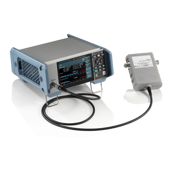
63. 3.1.8 Connecting Power Sensors The R&S NRT2 supports the R&S NRT‑Zxx directional power sensors listed in the data sheet. You have two choices for connecting the power sensors, but only one measure- ment at a time is possible. -
Page 20: Usb 2.0 Host Interfaces
1. Connect the R&S NRT‑Z5 USB interface adapter to the R&S NRT‑Zxx power sen- sor. 2. Connect the USB connector of the adapter to the R&S NRT2. 3. Connect the R&S NRT‑Zxx power sensor between source and load. See Chap- ter 3.1.8.1, "NRT Sensor... -
Page 21: Switching On Or Off
® Getting Started R&S NRT2 Preparing for Use 3.1.10 Switching On or Off Table 3-1: Overview of power states Status Position of power switch Standby orange Ready green To switch on the product The product is off but connected to power. -
Page 22: Instrument Tour
24. 3.2.1.1 NRT Sensor See (1) in Figure 3-2. To the left of the display, the R&S NRT2 provides the sensor interface. For supported power sensors, see the product brochure. Further information: ● Chapter 3.1.8, "Connecting Power Sensors", on page 19 3.2.1.2... -
Page 23: Keys
R&S NRT2 Instrument Tour The R&S NRT2 displays results in panes. Depending on the measurement mode, val- ues are displayed digitally or graphically. False triggers can occur If an object (e.g. a human finger) that is charged with static electricity is brought near the touch panel, false triggers can occur. -
Page 24: Usb Host Interface
58. If you press [Preset] again, the preset function starts. "Preset" on page 59. If you press the [Preset] key during booting, the R&S NRT2 starts with the factory default state. [Zero] Pressing [Zero] opens the "Zeroing Sensors" dialog. -
Page 25: On/Standby Key
21 3.2.2 Rear Panel Tour Figure 3-3: Rear panel of the R&S NRT2 1 = Trig In / Out 2 and Out 1 / Trig Out connectors, see Chapter 3.2.2.1, "Trig In / Out 2 and Out 1 / Trig Out Connectors",... -
Page 26: Ethernet Interface
"Connecting to power" on page 10. When the R&S NRT2 is connected to the AC supply, it automatically sets itself to the correct range for the applied voltage. The range is printed on the casing. There is no need to set the voltage manually. -
Page 27: Name Plate
NRT2 Instrument Tour IEC bus (IEEE 488) interface for remote control of the R&S NRT2. Used to connect a controller to remote control the R&S NRT2. Use a shielded cable for the connection. Characteristics of the IEC bus (IEEE 488) interface: ●... -
Page 28: Operating Concepts
● Remote Control....................... 35 4.1 Manual Operation Using the graphical user interface of the R&S NRT2 and the keys on the front panel, you can easily configure the settings and measure in the provided measurement modes. Using the touchscreen A touchscreen allows you to interact with the software using various finger gestures on the screen. -
Page 29: Measurement Pane
® Operating Concepts R&S NRT2 Manual Operation Figure 4-1: Start dialog 1 = Measurement pane, see Chapter 4.1.1.1, "Measurement Pane", on page 29. 2 = Connected sensor 3 = Title 4 = Measurement type 5 = Notification center status, see Chapter 4.1.3, "Notification... -
Page 30: Status Information
® Operating Concepts R&S NRT2 Manual Operation Figure 4-2: Layout of the measurement pane 1 = Displayed measurement value or graph 2 = Displayed settings 3 = Displayed limit values ► Tap the displayed settings, (1) in Figure 4-2, to access the sensor settings. -
Page 31: Notification Center
R&S NRT2 is in remote control. Manual operation is disabled. Identification and initialization of a connected power sensor is in progress. 4.1.3 Notification Center The notification center collects all information during the operation of the R&S NRT2: ● Notices ● Warning messages ●... - Page 32 ® Operating Concepts R&S NRT2 Manual Operation Symbol Description At least one warning message is present. Yellow is the assigned color. At least one error message is present. Red is the assigned color. To display the messages ► Tap the notification symbol in the upper left corner.
-
Page 33: Editing Parameters
® Operating Concepts R&S NRT2 Manual Operation 4.1.4 Editing Parameters 1. Tap a parameter to change its value. Depending on the selected parameter, a numeric or an alphanumeric editor is dis- played. 2. Tap to display the value range of the parameter ("Min", "Max"). -
Page 34: Remote Operation
R&S NRT2 simultaneously. By default, VNC access is enabled. Any user in the network who knows the password and IP address of the R&S NRT2 can access the R&S NRT2. To prevent access, dis- able the VNC server service under "VNC"... -
Page 35: Remote Control
Ctrl + E [Zero] Ctrl + N 4.3 Remote Control The R&S NRT2 is equipped with various interfaces for connecting it to a controller for remote control: ● IEC/IEEE bus interface (standard equipment) in line with the standards IEC 60625.1 (IEEE 488.1) and IEC 60625.2 (IEEE 488.2) ●... -
Page 36: Switching To Remote Control (Remote)
4.3.2 Returning to Manual Operation (LOCAL) If the R&S NRT2 is in remote control, you can display settings using the front-panel keys and the touchscreen, but you cannot change settings. To do that, you have to return to manual operation. -
Page 37: Measurement And Display Configuration
NRT2 Main Measurement Dialog 5 Measurement and Display Configuration The R&S NRT2 performs power reflection measurements with the R&S NRT‑Zxx direc- tional power sensor. The R&S NRT‑Zxx directional power sensor measures the forward and reverse power. The forward power is the power flux from the source to the load. -
Page 38: Forward
® Measurement and Display Configuration R&S NRT2 Main Measurement Dialog The R&S NRT2 displays the forward and reverse power simultaneously. One scalar value for the selected Forward measurement, and one scalar value for the Reflection measurement. Forward......................... 38 └ Average......................39 └... -
Page 39: Average
® Measurement and Display Configuration R&S NRT2 Main Measurement Dialog Average ← Forward Average power Remote command: CALCulate<Measurement>[:CHANnel<Channel>]:FEED "POWer:FORWard:AVERage" CCDF ← Forward Complementary cumulative distribution function. Probability that the envelope power is higher than the threshold set under "CCDF Threshold"... -
Page 40: (Pep)
Remote command: CALCulate<Measurement>[:CHANnel<Channel>]:FEED "POWer:ABSorption:PEP" Burst Average ← Forward Average power within a burst. The R&S NRT2 determines the average burst power by multiplying the average power with the ratio of burst period to burst width: Burst period Average Burst average =... -
Page 41: Standing Wave Ratio (Swr)
® Measurement and Display Configuration R&S NRT2 Main Measurement Dialog Standing Wave Ratio (SWR) ← Reflection 1 + Reflection coefficient Standing wave ratio = 1 - Reflection coefficient See also "Reflection Coefficient" on page 41. Remote command: CALCulate<Measurement>[:CHANnel<Channel>]:FEED "POWer:SWRatio" UNIT<Measurement>:POWer:REFLection Return Loss ←... -
Page 42: Forward Reference Value, Reflection Reference Value
® Measurement and Display Configuration R&S NRT2 Main Measurement Dialog Forward Reference Value, Reflection Reference Value ← Rel Available if Forward Relative State, Reflection Relative State is set to "On" or "Set". Sets the reference value. Remote command: CALCulate<Measurement>:RELative<DirectionalChannel>:CCDF CALCulate<Measurement>:RELative<DirectionalChannel>:POWer CALCulate<Measurement>:RELative<DirectionalChannel>:RATio:... -
Page 43: Measurement Overview
® Measurement and Display Configuration R&S NRT2 Measurement Overview CALCulate<Measurement>:METer<DirectionalChannel>:LOWer[:DATA]: RATio[:VALue] CALCulate<Measurement>:METer<DirectionalChannel>:LOWer[:DATA][: POWer] Forward Scale Upper Limit, Reflection Scale Upper Limit ← Scale Defines the upper limit of the bargraph display. Remote command: CALCulate<Measurement>:METer<DirectionalChannel>:UPPer[:DATA]: CCDF CALCulate<Measurement>:METer<DirectionalChannel>:UPPer[:DATA]: RATio:RCOefficient CALCulate<Measurement>:METer<DirectionalChannel>:UPPer[:DATA]: RATio:RFRatio CALCulate<Measurement>:METer<DirectionalChannel>:UPPer[:DATA]: RATio:RLOSs CALCulate<Measurement>:METer<DirectionalChannel>:UPPer[:DATA]:... -
Page 44: Measurement Main Configuration Dialog
® Measurement and Display Configuration R&S NRT2 Measurement Main Configuration Dialog The "Measurement Overview" dialog offers access to all measurement- and sensor- related settings. Further information: ● Chapter 5.3, "Measurement Main Configuration Dialog", on page 44 ● Chapter 5.6, "Measurement Representation",... -
Page 45: Controlling The Measurement
® Measurement and Display Configuration R&S NRT2 Controlling the Measurement Figure 5-2: Measurement Main Configuration dialog Channel Sensor Assigns the power sensor to the measurement. Trigger Mode "Trigger Mode" on page 47. Trigger Source "Trigger Source" on page 47. Forward "Forward"... -
Page 46: Triggering
® Measurement and Display Configuration R&S NRT2 Triggering ● Do you want to output each new average value as a measurement result or do you want to bundle more measured values into one result? Further information: ● Chapter 5.5, "Triggering", on page 46 5.5 Triggering... -
Page 47: Trigger Settings
® Measurement and Display Configuration R&S NRT2 Measurement Representation 5.5.3 Trigger Settings Access:"Measurement Overview" > "Measurement" > "Measurement Main Configura- tion". Chapter 5.3, "Measurement Main Configuration Dialog", on page 44. Trigger Mode......................... 47 Trigger Source.......................47 Trigger Mode Controls the trigger execution depending on the settings under "Trigger Source"... -
Page 48: Resolution
® Measurement and Display Configuration R&S NRT2 Measurement Representation Configures the measurement representation on the display. Resolution........................48 Forward Unit........................48 Display Format......................48 Max Hold Function......................49 Hold........................49 Limit Monitor........................49 └ Forward Lower Limit State, Reflection Lower Limit State....... 49 └... -
Page 49: Max Hold Function
111 CALCulate<Measurement>:DMODe Max Hold Function For all measurement functions, the R&S NRT2 stores the maximum and minimum val- ues and the calculated differences between these values. The selected setting applies to both power and reflection indication. You can change at any time. -
Page 50: Forward Upper Limit State, Reflection Upper Limit State
® Measurement and Display Configuration R&S NRT2 Measurement Representation CALCulate<Measurement>:LIMit<DirectionalChannel>:LOWer[:DATA]: RATio:SWR CALCulate<Measurement>:LIMit<DirectionalChannel>:LOWer[:DATA]: RATio[:VALue] Forward Upper Limit State, Reflection Upper Limit State ← Limit Monitor Enables or disables the monitoring function for the upper limit. Remote command: CALCulate<Measurement>:LIMit<DirectionalChannel>:UPPer:STATe Forward Upper Limit, Reflection Upper Limit ← Limit Monitor Defines an upper limit. -
Page 51: Sensor Configuration
® Sensor Configuration R&S NRT2 Mode Settings 6 Sensor Configuration The "Channel Configuration" dialog offers access to all sensor-related settings. Access: "Measurement Overview" > "Channel Sensor Configuration" An R&S NRT‑Zxx directional power sensor has two measurement channels, one chan- nel for forward power and one channel for reverse power. - Page 52 Bandwidth. "User" Define the duty cycle by: ● Burst Period ● Burst Width The R&S NRT2 calculates the average burst power from these val- ues. Remote command: CALCulate<Measurement>[:CHANnel<Channel>]:NRT:BURSt:MODE Burst Period Available if "User" is set under "Burst Mode" on page 52.
-
Page 53: Correction Settings
® Sensor Configuration R&S NRT2 Correction Settings Sets the burst width. Remote command: CALCulate<Measurement>[:CHANnel<Channel>]:NRT:BURSt:WIDTh Direction Defines how the forward power is determined. "Auto" Determines the power flow direction automatically. The greater value of two measured values is automatically assigned as forward power. - Page 54 ® Sensor Configuration R&S NRT2 Correction Settings Offset Reference Plane....................54 Offset..........................54 Modulation........................54 WCDMA Chip Rate....................... 55 Offset Reference Plane Selects the power sensor port to which the measurement results are referred to. "Source" Source connector of the R&S NRT‑Zxx power sensor "Load"...
-
Page 55: Sensor Frequency
® Sensor Configuration R&S NRT2 Sensor Frequency "IS95" IS- 95 CDMA standard for base stations. "WCDMA" WCDMA standard for base stations. "DVBT" DVB-T standard for terrestrial DVB TV transmitters. "DAB" DAB standard for radio transmitters. Remote command: CALCulate<Measurement>[:CHANnel<Channel>]:NRT:DMODulation[: VALue] [SENSe<Sensor>:]DM:STATe [SENSe<Sensor>:]DM:STANdard... -
Page 56: Filter Settings
® Sensor Configuration R&S NRT2 Filter Settings Remote command: on page 152 [SENSe<Sensor>:]FREQuency[:CW] 6.4 Filter Settings Access: "Measurement Overview" > "Channel Sensor Configuration" > "Filter" Video Bandwidth......................56 Integration Time Mode....................56 Integration Time......................57 Averaging Mode......................57 Averaging Count......................57... - Page 57 ® Sensor Configuration R&S NRT2 Filter Settings Remote command: CALCulate<Measurement>[:CHANnel<Channel>]:NRT:APERture:MODE Integration Time Available if Integration Time Mode is set to "User". Defines the integration time for a single measurement. Remote command: CALCulate<Measurement>[:CHANnel<Channel>]:NRT:APERture[:VALue] Averaging Mode Sets the averaging mode. "User" Define the value under Averaging Count.
-
Page 58: Saving And Recalling Settings
NRT2 7 Saving and Recalling Settings When shutting down, the R&S NRT2 saves the measurement settings. When booting the next time, the R&S NRT2 uses the settings from the last session. See also Chap- ter 3.1.10, "Switching On or Off", on page 21. - Page 59 Recall..........................59 Preset Sets the R&S NRT2 and the connected R&S power sensors to a defined initial state. Thus, you can change parameter values from a well defined starting point. For details on sensor settings, see the user manual of the R&S power sensor.
-
Page 60: Zeroing Sensors
® Zeroing Sensors R&S NRT2 8 Zeroing Sensors Zeroing removes offset voltages from the analog circuitry of the sensors, so that there are only low powers displayed when there is no power applied. Zeroing is recommended if: ● The temperature has varied by more than 5 K. - Page 61 ® Zeroing Sensors R&S NRT2 Remote command: ● CALibration<Sensor>:ZERO User Manual 1178.5550.02 ─ 04...
-
Page 62: System Settings
® System Settings R&S NRT2 Connections 9 System Settings The system settings do not affect the measurements directly. Access: [System] Figure 9-1: System Overview dialog The "System Overview" dialog is divided into the following tabs: ● Connections......................62 ● Instrument Info...................... -
Page 63: Network Settings
9.1.1 Network Settings Access: [System] > "Connections" > "Network" Contains the settings for integrating the R&S NRT2 in a network. There are two meth- ods to establish a network connection between R&S NRT2 and computer: ► Connect both to a common network (infrastructure network). - Page 64 During this time, you cannot address the R&S NRT2. After the restart, you can only address the R&S NRT2 using the newly set hostname. Note: It is recommended that you do not change the default hostname to avoid prob- lems with the network connection.
- Page 65 SYSTem:COMMunicate:NETWork[:IPADdress]:MODE SYSTem:COMMunicate:INET[:SELF]:MODE DNS Suffix ← IPv4 tab Sets the primary DNS suffix, that means the domain name. DNS uses the suffix for registration and name resolution to identify the R&S NRT2 uniquely in the entire net- work. Remote command: SYSTem:COMMunicate:NETWork[:COMMon]:DOMain SYSTem:COMMunicate:INET[:SELF]:DNS:SUFFix User Manual 1178.5550.02 ─...
-
Page 66: Remote Settings
R&S NRT2 Connections IPv4 Address ← IPv4 tab Available if "Static" is set under Address Mode. Sets the IP address of the R&S NRT2. Remote command: SYSTem:COMMunicate:NETWork[:IPADdress][:ADDRess] SYSTem:COMMunicate:INET[:SELF]:ADDRess Subnet Mask ← IPv4 tab Available if "Static" is set under Address Mode. -
Page 67: Visa Resource Tab
In a LAN, the VISA resource string is required to establish a communication session between the controller and the R&S NRT2. The resource string is a unique identifier, composed of the specific IP address of the instrument and some network and VISA- specific keywords. -
Page 68: Gpib Address
Emulations tab Language ← Emulations tab Fixed value. "SCPI" Native remote command set of the R&S NRT2, based on the stan- dard commands for programmable instruments (SCPI-99). Customization of *IDN? ← Emulations tab Sets which identification string is used. "Off"... -
Page 69: Input/Output Settings (I/O)
└ Fail Voltage..................... 71 I/O 1, I/O 2 tabs Configures the two multifunctional BNC connectors at the rear of the R&S NRT2, see Chapter 3.2.2.1, "Trig In / Out 2 and Out 1 / Trig Out Connectors", on page 25. - Page 70 ® System Settings R&S NRT2 Connections Figure 9-2: Example Mode ← I/O 1, I/O 2 tabs Sets the functionality of the Out 1 / Trig Out and Trig In / Out 2 connectors. "Off" Disables the connector. "Forw Analog Out", "Refl Analog Out"...
-
Page 71: Sensor Manager
® System Settings R&S NRT2 Connections Remote command: OUTPut:RECorder<output>:LIMit:LOWer:CCDF OUTPut:RECorder<output>:LIMit:LOWer[:POWer] OUTPut:RECorder<output>:LIMit:LOWer:RATio:RCOefficient OUTPut:RECorder<output>:LIMit:LOWer:RATio:RFRatio OUTPut:RECorder<output>:LIMit:LOWer:RATio:RLOSs OUTPut:RECorder<output>:LIMit:LOWer:RATio:SWR OUTPut:RECorder<output>:LIMit:LOWer:RATio[:VALue] 2.5 V Equivalent ← I/O 1, I/O 2 tabs Available if Mode is set to: ● "Forw Analog Out" ● "Refl Analog Out" Enter the measurement value that corresponds to 2.5 V output voltage. - Page 72 ® System Settings R&S NRT2 Connections The R&S NRT2 displays the recognized power sensors. Symbol Description Info icon Tap to open the "Sensor Info" dialog, see "Sensor Info" on page 72. The sensor manager gives access to: Sensor Info........................72 └...
- Page 73 ® System Settings R&S NRT2 Connections Remote command: [SENSe<Sensor>:]INFormation? Sensor Test ← Sensor Info Tap "Start Test" to start a selftest of the connected power sensor. The selftest provides detailed information that you can use for troubleshooting. "Test Verdict" Shows the status of the selftest.
-
Page 74: Instrument Info
® System Settings R&S NRT2 Instrument Info 9.2 Instrument Info Access: [System] > "Instrument Info" For displaying information on a connected power sensor, see "Sensor Info" on page 72. On this tab, you display and configure the following settings: ●... - Page 75 Date and Time Settings....................76 └ Date........................ 76 └ Time........................ 76 └ Time Zone Region..................76 └ Time Zone.......................76 System Info Displays the information on the R&S NRT2: ● "Manufacturer" ● "Type" ● "Stock Number" Chapter 3.2.2.7, "Name Plate", on page 27. ●...
- Page 76 Instrument identification string: <manufacturer>,NRT2,<serial number>,<firmware version> ● "*OPT?" Option identification string; lists the installed options: <option 1>, <option 2>, ..● "Uptime" Operating time of the R&S NRT2 Remote command: SYSTem:INFO[:INFO]? SYSTem:DID? SYSTem:DEVice:ID? Date and Time Settings Opens the "Date and Time" dialog.
-
Page 77: Security Settings
® System Settings R&S NRT2 Instrument Info Remote command: SYSTem:TIME:DSTime:RULE SYSTem:TIME:DSTime:RULE:CATalog? 9.2.2 Security Settings Access: [System] > "Instrument Info" > "Security" Contains the settings for access rights, LAN security and passwords. The "Security" dialog is divided into the following tabs: General tab........................ -
Page 78: Security Password To Unlock Settings
Volatile Mode ← General tab If enabled, the R&S NRT2 does not save changed settings in the non-volatile memory. After a reboot, the R&S NRT2 has the same configuration as at the time when you enabled the volatile mode. Use the volatile mode if you want to reboot with a defined configuration for a measure- ment setup, regardless off any settings made manually or by remote control. -
Page 79: Lan Services
Enables or disables the LAN services in general. If enabled, it provides remote access via all unlocked services. SCPI over LAN ← LAN Settings tab Enables or disables the access over LAN to control the R&S NRT2 remotely by using SCPI (standard commands for programmable instruments) commands. Web Server ← LAN Settings tab Fixed value. -
Page 80: Option Settings
Currently used security password. The preconfigured password is 123456. Note: We recommend that you change the preconfigured password before connecting the R&S NRT2 to a network. The security password is required for changing security settings in the "Security" dia- log. - Page 81 ® System Settings R&S NRT2 Instrument Info Remote command: on page 106 *OPT? Details tab Displays the installed hardware options. If you want to see more information on a specific option, tap User Manual 1178.5550.02 ─ 04...
-
Page 82: Open Source Licenses
9.2.4 Open Source Licenses Access: [System] > "Instrument Info" > "Open Source Licenses" Displays the license texts of open source software packages used in the R&S NRT2 software. Under "Component", select the open source software package you want to display the license text of. -
Page 83: Test
System Settings R&S NRT2 Test Lists the hardware details of the R&S NRT2 assemblies. This tab can be useful for looking up the revision of hardware, for example when troubleshooting. 9.4 Test Access: [System] > "Test" On this tab, you can test whether the user interfaces are in working order and create information useful for troubleshooting. -
Page 84: Global Settings
® System Settings R&S NRT2 Global Settings Testing the user interfaces 1. Tap the test you want to perform. A dialog with detailed test instructions is displayed. 2. Read and follow the instructions. 3. Exit the test. Note: "Exit with PASS" only becomes available when the test is finished success- fully. - Page 85 ® System Settings R&S NRT2 Global Settings On this tab, you configure the following settings: Visualize Non-Preset State................... 85 Tabs Position.........................85 Visualize Non-Preset State If enabled, a setting that differs from the preset value is indicated by a pencil symbol.
-
Page 86: Firmware Update
This chapter contains information on installing/updating the firmware on the R&S NRT2 via PC and USB or Ethernet connection. Use the Firmware Update program (PureFW) to load new firmware for the R&S NRT2. It is part of the R&S NRP Toolkit. -
Page 87: Preparing An Update
1. Make sure a recent VISA software is installed. Firmware update with PureFW can only be performed with the device recognized as a VISA device. 2. Connect the R&S NRT2 to the PC using a USB cable. If the instrument is off, switch it on. -
Page 88: Updating The Application Firmware
® Firmware Update R&S NRT2 Firmware Update via PC and USB or Ethernet Connection 3. Register the instrument as a VISA device. Refer to documentation of your VISA software for details. 10.1.3 Updating the Application Firmware To perform a firmware update: 1. - Page 89 ® Firmware Update R&S NRT2 Firmware Update via PC and USB or Ethernet Connection b) If the instrument is connected to the network, enter the hostname or the IP address of the instrument in the field "Manually add a Raw SCPI Device" and then press "Check and Add"...
- Page 90 4. In the "Firmware" field enter the full path and file name of the update file or press the ellipsis button to browse the file system for it. New firmware for the R&S NRT2 generally has an *.rsu (Rohde & Schwarz Update) extension.
-
Page 91: Firmware Update Via A Usb Flash Memory Stick
This chapter contains information on installing/updating the firmware on the R&S NRT2 via a USB flash memory stick. The R&S NRT2 supports this update method from version 02.xx of the installed firm- ware. With version 01.xx installed, perform an update to version 02.xx or later with the method described in section Chapter 10.1, "Firmware Update via PC and USB or... -
Page 92: Updating The Application Firmware
® Firmware Update R&S NRT2 Firmware Update via a USB Flash Memory Stick 2. Disconnect the USB flash memory stick from the PC or mobile device. If the instru- ment is off, switch it on. 10.2.3 Updating the Application Firmware To perform a firmware update: 1. -
Page 93: Remote Control
® Remote Control R&S NRT2 Notation for SCPI Commands 11 Remote Control For information on remote basics, see the Rohde & Schwarz website at www.rohde- schwarz.com/rc-via-scpi 11.1 Notation for SCPI Commands In the following sections, all commands implemented in the device are listed according to the command system and then described in detail. -
Page 94: Status Reporting System
® Remote Control R&S NRT2 Status Reporting System Example: Definition: OUTPut:AUDiobits <audiobits> Command: OUTP:AUD 24 Special characters | and { } A vertical bar in parameter definitions indicates alternative possibilities in the sense of "or". The effect of the command differs, depending on which parameter is used. -
Page 95: Structure Of A Scpi Status Register
® Remote Control R&S NRT2 Status Reporting System Output queue Error/event queue Service request enable Status byte & & & & Questionable status & & Standard event status RQS/MSS Operation status & Service request to controller at transition from 0 to 1 Figure 11-1: Status registers overview Chapter 11.2.3, "Status Byte (STB) and Service Request Enable Register... - Page 96 ® Remote Control R&S NRT2 Status Reporting System significant bit, is set to 0 in all registers, thus preventing problems some controllers have with the processing of unsigned integers. Figure 11-2: Standard SCPI status register CONDition status register part The five parts of a SCPI register have different properties and functions: The CONDition part is written into directly by the hardware or the sum bit of the next lower register.
-
Page 97: Status Byte (Stb) And Service Request Enable Register (Sre)
® Remote Control R&S NRT2 Status Reporting System EVENt status register part The EVENt part indicates whether an event has occurred since the last reading, it is the "memory" of the condition part. It only indicates events passed on by the transition filters. -
Page 98: Ist Flag And Parallel Poll Enable Register (Ppe)
® Remote Control R&S NRT2 Status Reporting System Table 11-1: Used status byte bits and their meaning Short description Bit is set if Error queue not empty The error queue has an entry. If this bit is enabled by the ser- vice request enable register, each entry of the error queue generates a service request. -
Page 99: Standard Event Status And Enable Register (Esr, Ese)
The measured values for power or matching exceed the limit values. ● The central supply voltage for power sensor and R&S NRT2 exceeds or falls below the allowed limits. NRT SERRRor Static error of the R&S NRT‑Zxx power sensor occurred. Warning 11.2.6 Standard Event Status and Enable Register (ESR, ESE) -
Page 100: Operation Status Register
® Remote Control R&S NRT2 Status Reporting System Operation Complete Query Error Device-Dependent Error Execution Error Command Error User Request Power On Figure 11-4: Standard event status register (ESR) Table 11-3: Used standard event status bits and their meaning Bit no. -
Page 101: Common Commands
Table 11-4: Used operation status bits and their meaning Bit no. Short description Bit is set if NRT MEASuring R&S NRT2 is measuring. NRT TRIGger R&S NRT2 is waiting for trigger event. NRT CALCulation R&S NRT2 performs a limit check. 11.3 Common Commands ........................... 102 &ABO ........................... 102 &DFC... - Page 102 ® Remote Control R&S NRT2 Common Commands ..........................104 *DMC ..........................104 *EMC ..........................104 *ESE ...........................104 *ESR? .......................... 104 *GCLS ..........................105 *GMC? ........................105 *GOPC? .......................... 105 *GWAI ..........................105 *IDN? ..........................105 *IST? .......................... 105 *LMC? ..........................106 *OPC ...........................106 *OPT? ..........................106 *PMC ..........................
- Page 103 ® Remote Control R&S NRT2 Common Commands >L Goto local Usage: Event >M Goto local with remote state. Usage: Event >R Goto remote Usage: Event &HFC Hardware flow control Usage: Event &LLO Local lockout Usage: Event &NREN Not remote enabled (goto local)
-
Page 104: Dmc
® Remote Control R&S NRT2 Common Commands *DEV [<instrument_no>] This command returns the selected "instrument" of the device. The command can be used to select between different "instruments" in a multichannel device. Parameters: <instrument_no> The assigned instrument. *DMC <Label>, <Macro>... -
Page 105: Gmc
® Remote Control R&S NRT2 Common Commands *GMC? <Label> Get macro content. Query parameters: <Label> Return values: <Macro> <dblock> Usage: Query only *GOPC? Analogon of *OPC? for all instruments in multichannel device. Return values: <gopc> "1" is return if all pending operations in all internal "instruments"... -
Page 106: Opc
® Remote Control R&S NRT2 Common Commands Usage: Query only *OPC OPeration Complete Sets bit 0 in the event status register when all preceding commands have been execu- ted. This bit can be used to initiate a service request. *OPC must be sent at the end of a program message. -
Page 107: Psc
® Remote Control R&S NRT2 Common Commands *PSC <psc> Writes/reads the power on status clear flag (PSC). Parameters: <psc> Power on status clear flag. *RCL <number> ReCaLl Calls the device state which has been stored with the command under the speci- *SAV fied number. -
Page 108: Sre
® Remote Control R&S NRT2 Common Commands Manual operation: "Save" on page 59 *SRE <register> Service Request Enable Sets the service request enable register to the specified value. This command deter- mines under which conditions a service request is triggered. -
Page 109: Wai
® Remote Control R&S NRT2 Common Commands Example: *TST? Query Response: Passed Example: *TST? Query Response: Failed Usage: Query only *WAI WAIt to continue Prevents the execution of the subsequent commands until all preceding commands have been executed and all signals have settled. -
Page 110: Calculate
® Remote Control R&S NRT2 CALCulate *XSRE <xsre> The service request enable register. This command can be used to enable service requests. Parameters: <xsre> <expr> Service request enable register (SRE). *XSTB? Reads the status byte. Return values: <xstb> <expr> Status byte (STB). - Page 111 ® Remote Control R&S NRT2 CALCulate ..120 CALCulate<Measurement>:METer<DirectionalChannel>:UPPer[:DATA]:RATio:RFRatio ..120 CALCulate<Measurement>:METer<DirectionalChannel>:UPPer[:DATA]:RATio:RLOSs .... 121 CALCulate<Measurement>:METer<DirectionalChannel>:UPPer[:DATA]:RATio:SWR ..121 CALCulate<Measurement>:METer<DirectionalChannel>:UPPer[:DATA]:RATio[:VALue] ....121 CALCulate<Measurement>:METer<DirectionalChannel>:UPPer[:DATA][:POWer] ........122 CALCulate<Measurement>:RELative<DirectionalChannel>:CCDF ........122 CALCulate<Measurement>:RELative<DirectionalChannel>:POWer ....122 CALCulate<Measurement>:RELative<DirectionalChannel>:RATio:RCOefficient ......123 CALCulate<Measurement>:RELative<DirectionalChannel>:RATio:RFRatio ......123 CALCulate<Measurement>:RELative<DirectionalChannel>:RATio:RLOSs ......123 CALCulate<Measurement>:RELative<DirectionalChannel>:RATio:SWR ......124 CALCulate<Measurement>:RELative<DirectionalChannel>:RATio[:VALue] ........124...
- Page 112 ® Remote Control R&S NRT2 CALCulate Suffix: <Measurement> 1...100 Parameters: <function> MAX | MIN | DIFFerence *RST: Manual operation: "Max Hold Function" on page 49 CALCulate<Measurement>:HOLD[:STATe] <state> Enables or disables the MaxHold function or reset the currently hold values. Suffix: <Measurement>...
- Page 113 ® Remote Control R&S NRT2 CALCulate CALCulate<Measurement>:LIMit<DirectionalChannel>:LOWer[:DATA]:RATio: RCOefficient <value> Lower limit value for reflection coefficient. Suffix: <Measurement> 1...100 <DirectionalChannel> 1..2 Parameters: <value> Range: -1e18 to 1e18 *RST: Default unit: - Manual operation: "Forward Lower Limit, Reflection Lower Limit" on page 49 CALCulate<Measurement>:LIMit<DirectionalChannel>:LOWer[:DATA]:RATio:...
- Page 114 ® Remote Control R&S NRT2 CALCulate CALCulate<Measurement>:LIMit<DirectionalChannel>:LOWer[:DATA]:RATio: SWR <value> Lower limit value for SWR. Suffix: <Measurement> 1...100 <DirectionalChannel> 1..2 Parameters: <value> Range: 0.0 to 1e18 *RST: Default unit: - Manual operation: "Forward Lower Limit, Reflection Lower Limit" on page 49 CALCulate<Measurement>:LIMit<DirectionalChannel>:LOWer[:DATA]:RATio[:...
- Page 115 ® Remote Control R&S NRT2 CALCulate Suffix: <Measurement> 1...100 <DirectionalChannel> 1..2 Parameters: <state> *RST: Manual operation: "Forward Upper Limit State, Reflection Upper Limit State" on page 50 CALCulate<Measurement>:LIMit<DirectionalChannel>:UPPer[:DATA]:CCDF <value> Upper limit value for CCDF. Suffix: <Measurement> 1...100 <DirectionalChannel> 1..2 Parameters: <value>...
- Page 116 ® Remote Control R&S NRT2 CALCulate Parameters: <value> Range: 0.0 to 100.0 *RST: 100.0 Default unit: pct Manual operation: "Forward Upper Limit, Reflection Upper Limit" on page 50 CALCulate<Measurement>:LIMit<DirectionalChannel>:UPPer[:DATA]:RATio: RLOSs <value> Upper limit value for return loss. Suffix: <Measurement> 1...100 <DirectionalChannel>...
- Page 117 ® Remote Control R&S NRT2 CALCulate Parameters: <value> Range: 1e-18 to 1e18 *RST: 100.0 Default unit: - Manual operation: "Forward Upper Limit, Reflection Upper Limit" on page 50 CALCulate<Measurement>:LIMit<DirectionalChannel>:UPPer[:DATA][:POWer] <value> Upper limit value for power value. Suffix: <Measurement> 1...100 <DirectionalChannel> 1..2 Parameters: <value>...
- Page 118 ® Remote Control R&S NRT2 CALCulate Parameters: <value> Range: -1e18 to 1e18 *RST: Default unit: - Manual operation: "Forward Scale Lower Limit, Reflection Scale Lower Limit" on page 42 CALCulate<Measurement>:METer<DirectionalChannel>:LOWer[:DATA]:RATio: RFRatio <value> Lower limit value for ratio of forward/reverse power bargraph display.
- Page 119 ® Remote Control R&S NRT2 CALCulate Parameters: <value> Range: 0.0 to 1e18 *RST: Default unit: - Manual operation: "Forward Scale Lower Limit, Reflection Scale Lower Limit" on page 42 CALCulate<Measurement>:METer<DirectionalChannel>:LOWer[:DATA]:RATio[: VALue] <value> Lower limit value for power ratio bargraph display.
- Page 120 ® Remote Control R&S NRT2 CALCulate Parameters: <value> Range: 0.0 to 100.0 *RST: 100.0 Default unit: pct Manual operation: "Forward Scale Upper Limit, Reflection Scale Upper Limit" on page 43 CALCulate<Measurement>:METer<DirectionalChannel>:UPPer[:DATA]:RATio: RCOefficient <value> Upper limit value for reflection coefficient bargraph display.
- Page 121 ® Remote Control R&S NRT2 CALCulate Parameters: <value> Range: -200.0 to 200.0 *RST: 200.0 Default unit: dB Manual operation: "Forward Scale Upper Limit, Reflection Scale Upper Limit" on page 43 CALCulate<Measurement>:METer<DirectionalChannel>:UPPer[:DATA]:RATio: SWR <value> Upper limit value for SWR bargraph display.
- Page 122 ® Remote Control R&S NRT2 CALCulate Parameters: <value> Range: 1e-15 to 1e12 *RST: 1e-2 Default unit: W Manual operation: "Forward Scale Upper Limit, Reflection Scale Upper Limit" on page 43 CALCulate<Measurement>:RELative<DirectionalChannel>:CCDF <value> Relative limit value for CCDF. Suffix: <Measurement> 1...100 <DirectionalChannel>...
- Page 123 ® Remote Control R&S NRT2 CALCulate Parameters: <value> Range: 0.0 to 1.0 *RST: Default unit: - Manual operation: "Forward Reference Value, Reflection Reference Value" on page 42 CALCulate<Measurement>:RELative<DirectionalChannel>:RATio:RFRatio <value> Relative value for ratio of forward/reverse power. Suffix: <Measurement> 1...100 <DirectionalChannel> 1..2 Parameters: <value>...
- Page 124 ® Remote Control R&S NRT2 CALCulate Parameters: <value> Range: 0.0 to 1.0 *RST: Default unit: - Manual operation: "Forward Reference Value, Reflection Reference Value" on page 42 CALCulate<Measurement>:RELative<DirectionalChannel>:RATio[:VALue] <value> Relative value for power ratio. Suffix: <Measurement> 1...100 <DirectionalChannel> 1..2 Parameters: <value>...
- Page 125 ® Remote Control R&S NRT2 CALCulate Manual operation: "Resolution" on page 48 CALCulate<Measurement>[:CHANnel<Channel>]:AVERage:COUNt:AUTO[: STATe] <state> Enables or disables the mode for determining the Average Count automatically from the level of the input signal. Suffix: <Measurement> 1...100 <Channel> 1...2 Parameters: <state>...
- Page 126 ® Remote Control R&S NRT2 CALCulate CALCulate<Measurement>[:CHANnel<Channel>]:CORRection:OFFSet:STATe <state> Enables or disables a selected frequency dependent offset table per channel. Suffix: <Measurement> 1...100 <Channel> 1...2 Parameters: <state> *RST: Manual operation: "Offset" on page 54 CALCulate<Measurement>[:CHANnel<Channel>]:CORRection:OFFSet[: MAGNitude] <value> Sets an offset correction value for the selected reference plane. This can correct the influence of cables etc.
- Page 127 ® Remote Control R&S NRT2 CALCulate Manual operation: "Average" on page 39 "CCDF" on page 39 "Peak Envelope Power (PEP)" on page 39 "Absorption Average" on page 39 "Crest Factor (CF)" on page 39 "Absorption PEP" on page 40 "Burst Average"...
- Page 128 ® Remote Control R&S NRT2 CALCulate Suffix: <Measurement> 1...100 <Channel> 1...2 Parameters: <mode> AUTO | USER *RST: AUTO Manual operation: "Burst Mode" on page 52 CALCulate<Measurement>[:CHANnel<Channel>]:NRT:BURSt:PERiod <value> Period of a burst sequence (for selected burst USER mode). Suffix: <Measurement> 1...100 <Channel>...
- Page 129 ® Remote Control R&S NRT2 CALCulate Parameters: <value> Range: 0.0 to 100e6 *RST: 0.001 Default unit: W Manual operation: "CCDF Threshold" on page 53 CALCulate<Measurement>[:CHANnel<Channel>]:NRT:DIRection <direction> Selects the direction of forward power relative to defined ports 1 and 2. In AUTO mode the port with the greater measured power is interpreted as forward power.
- Page 130 ® Remote Control R&S NRT2 CALCulate Manual operation: "Modulation" on page 54 CALCulate<Measurement>[:CHANnel<Channel>]:NRT:PEP:HOLD:TIME <value> Specifies the hold time of the peak hold circuit. If the entry is valid, the USER mode is automatically switched on and the default setting is switched off.
-
Page 131: Calibration
® Remote Control R&S NRT2 DIAGnostic CALCulate<Measurement>:LIMit:TYPE <type> The command allows selection of the value to be output. Suffix: <Measurement> 1...100 Parameters: <type> MAX | MIN | DIFFerence MAXimum Maximum value MINimum Minimum value DIFFerence Difference between maximum and minimum value... -
Page 132: Format
® Remote Control R&S NRT2 FREQuency Usage: Query only 11.7 FORMat ......................132 FORMat:SREGister ......................132 FORMat[:DATA] FORMat:SREGister <sregister> Specifies which format is used for the return value of *STB?. Parameters: <sregister> ASCii | HEXadecimal | OCTal | BINary *RST: ASCii... -
Page 133: Input
® Remote Control R&S NRT2 INPut 11.9 INPut ..................133 INPut<Sensor>:PORT:OFFSet ..................133 INPut<Sensor>:PORT:POSition ................133 INPut<Sensor>:PORT:SOURce[:VALue] ................134 INPut<Sensor>:PORT:SOURce:AUTO INPut<Sensor>:PORT:OFFSet <offs> This command allows the transmission loss in a cable connecting the desired mea- surement point and the sensor to be taken into account. If the measurement position is set to LOAD, i.e. -
Page 134: Mmemory
® Remote Control R&S NRT2 MMEMory INPut<Sensor>:PORT:SOURce:AUTO <auto> This command switches the automatic assignment of the forward direction on or off. Parameters: <auto> With automatic assignment of the forward direction, the direction in which the greater power flows is taken as the forward direc- tion. -
Page 135: Mmemory:attribute
® Remote Control R&S NRT2 MMEMory MMEMory:ALIases? {<alias>, <path>}... Reads the current list of predefined path aliases to be used with the MMEM com- mands. In case there are no aliases defined, a single empty string is returned. Return values: <alias>... -
Page 136: Mmemory:catalog:length
® Remote Control R&S NRT2 MMEMory Example: MMEM:ATTR? 'D:\USER\DATA\*.*' Returns a list of all files and their attributes in the D:\USER\DATA directory. MMEMory:CATalog? <path_name>[, <format>] Returns the subdirectories and files in the specified directory. If no directory and no drive are specified, the subdirectories and files in the default directory on the default drive are returned. -
Page 137: Mmemory:cdirectory
Writes the <data> to the file identified by <file_name>. The IEC/IEEE bus terminator should be set to EOI in order to ensure correct data transfer. The associated query transfers the specified file from the R&S NRT2 to the control computer. Make sure that the intermediate memory on the control computer is large enough to receive the file. -
Page 138: Mmemory:dcatalog
"MMEM:DATA 'TEST1.WV',#3767<block_data>" Writes the block data to the test1.wv file. MMEM:DATA? 'TEST1.WV' Sends the data of the Test1.wv file from the R&S NRT2 to the control computer in the form of a binary block. MMEMory:DCATalog? [<path_name>] Returns the subdirectories of the specified directory in a list. The subdirectory names are separated by commas. -
Page 139: Mmemory:dcatalog:length
® Remote Control R&S NRT2 MMEMory MMEMory:DCATalog:LENGth? [<path_name>] Returns the number of subdirectories in the specified directory. If no directory is speci- fied, the default directory is read out. Query parameters: <path_name> Return values: <file_entry_count> Response string: number of subdirectories. -
Page 140: Mmemory:load:macro
The *RCL command is used to load the immediate instrument setting. Setting parameters: <sav_rcl_state_number> 0: the instrument setting of the selected file is set directly in the R&S NRT2. ≠ 0: load the intermediate instrument setting using (for *RCL details see example). - Page 141 ® Remote Control R&S NRT2 MMEMory Example: MMEM:MDIR 'carrier' Creates the carrier subdirectory in the default directory. Usage: Setting only MMEMory:MOVE <file_source>, <file_destination> If no path is specified for <file_destination>, renames <file_source>. If a path is specified for <file_destination>, moves <file_source> to the specified path and stores it under its original file name or, if specified, under a new file name.
-
Page 142: Mmemory:rdirectory
® Remote Control R&S NRT2 MMEMory Setting parameters: <file_name> <msus> Usage: Setting only MMEMory:RDIRectory <directory_name> Deletes the specified subdirectory in the specified directory. If no directory is specified, the specified subdirectory is deleted in the default directory. Setting parameters: <directory_name>... -
Page 143: Output
® Remote Control R&S NRT2 OUTPut <msus> MMEM:STOR:STAT 0,'D:\USER\TEST1.ss' Example: Saves the current instrument setting in the TEST1.ss file in the USER directory on the internal hard disk. Example: MMEM:STOR:STAT 4,'D:\user\test4.savrcl' *SAV 4 Saves the test4.savrcl file in the user directory of the inter- nal hard disk. - Page 144 ® Remote Control R&S NRT2 OUTPut Connector 1 can be configured as analog output. Analog output may be a DA conver- sion of a measurement result or a signaling of a limit violation (0 V or 2.5 V). Connector 2 can be configured as analog output or as trigger input.
- Page 145 ® Remote Control R&S NRT2 OUTPut OUTPut:RECorder<output>:LIMit:LOWer[:POWer] <lower_limit> Specifies the lower power limit of the characteristic for one of the two analog outputs if the associated calculate block returns a power (unit DBM, W or DBUV) as measured value. Units: DBM | W | DBUV Suffix: <output>...
- Page 146 ® Remote Control R&S NRT2 OUTPut OUTPut:RECorder<output>:LIMit:LOWer:CCDF <value> Specifies the lower limit of the characteristic for one of the two analog outputs. Below this limit, the output is set to 0 V. Suffix: <output> 1...2 Parameters: <value> Range: -1e18 to 1e18...
- Page 147 ® Remote Control R&S NRT2 OUTPut Parameters: <value> Range: -180.0 to 180.0 *RST: Default unit: dB Manual operation: "0 V Equivalent" on page 70 OUTPut:RECorder<output>:LIMit:LOWer:RATio:SWR <value> Specifies the lower limit of the characteristic for one of the two analog outputs. Below this limit, the output is set to 0 V.
-
Page 148: Sense
® Remote Control R&S NRT2 SENSe OUTPut:RECorder<output>:LIMit:UPPer:RATio:RFRatio <value> Specifies the upper limit of the characteristic for one of the two analog outputs. Above this limit, the output is set to 2.5 V. Suffix: <output> 1...2 Parameters: <value> Range: -1e18 to 1e18 *RST: 100.0... - Page 149 ® Remote Control R&S NRT2 SENSe ............151 [SENSe<Sensor>:][POWer:][AVG:]APERture[:VALue] ................152 [SENSe<Sensor>:]FREQuency[:CW] ................152 [SENSe<Sensor>:]FREQuency:FIXed ..................152 SENSe<Sensor>:BURSt:MODE ..................153 SENSe<Sensor>:BURSt:PERiod ..................153 SENSe<Sensor>:BURSt:WIDTh ..................153 [SENSe<Sensor>:]DM:STANdard ..................154 [SENSe<Sensor>:]DM:STATe ................154 [SENSe<Sensor>:]DM:WCDMa:CRATe ....................154 [SENSe<Sensor>:]DATA? ................155 [SENSe<Sensor>:]FUNCtion:CONCurrent .............155 [SENSe<Sensor>:]FUNCtion:OFF:ALL<Channel> ................155 [SENSe<Sensor>:]FUNCtion:OFF[:FUNC] ................156 [SENSe<Sensor>:]FUNCtion:STATe? ..................156 [SENSe<Sensor>:]INFormation?
- Page 150 ® Remote Control R&S NRT2 SENSe [SENSe<Sensor>:]BWIDth:VIDeo:FNUMber <fnum> [SENSe<Sensor>:]BANDwidth:VIDeo:FNUMber <fnum> Sets the video bandwidth for the rectified RF. The setting mainly influences the mea- surement of the peak envelope power (PEP), determination of the crest factor (CF), the measurement of the average burst power and the complementary cumulative distribu- tion function (CCDF).
-
Page 151: [Sense
The two burst parameters must either be user-defined or the ratio is automatically determined by the NRT2. Manual entry of the parameters is possible any time and the sensors NRT-Z43/44 also allow automatic measurement. POWer:FORWard:PEP...:][Power:][Avg:]Aperture[:Value] -
Page 152: [Sense
® Remote Control R&S NRT2 SENSe Parameters: <integration_time> Range: 8.3e-9 to 30.0 *RST: 0.005 Default unit: s [SENSe<Sensor>:]FREQuency[:CW] <frequency> This command informs the NRT of the carrier frequency of the specified sensor. The entered frequency value is required to correct the frequency-dependent response of the sensor.:]Frequency[:Cw] -
Page 153: Sense
® Remote Control R&S NRT2 SENSe USER The duty cycle is defined by the burst width and burst period, on page 153 and SENSe<Sensor>:BURSt:PERiod on page 153. The NRT calcu- SENSe<Sensor>:BURSt:WIDTh lates the average burst power from this duty cycle and the aver- age power.:Burst:period -
Page 154: [Sense
® Remote Control R&S NRT2 SENSe [SENSe<Sensor>:]DM:STATe <state> This command switches the correction of the measurement value for modulated sig- nals on or off. Selection of a communication standard, see [SENSe<Sensor>:]DM: on page 153, is enabled only if the correction is switched on.:]Dm:state -
Page 155: [Sense
® Remote Control R&S NRT2 SENSe [SENSe<Sensor>:]FUNCtion:CONCurrent <concurrent> This command defines whether several measurement functions may be simultaneously activated. Parameters: <concurrent> Two measurement functions may be simultaneously active. If two measurement functions are mutually exclusive, the error message. –221 "Settings conflict“ is generated and the first set- ting retained.:]Function:concurrent -
Page 156: [Sense
® Remote Control R&S NRT2 SENSe Example: SENS2:FUNC:OFF "POW:REV" SENS2: FUNC:OFF? The following response would be possible: "POW:CFAC","POW:FORW:AVER:BURS", "POW:FORW:PEP", "POW:FORW:CCDF", "POW:ABS:AVER", "POW:ABS:AVER:BURS", "POW:ABS:PEP", "POW:REV" Usage: Setting only [SENSe<Sensor>:]FUNCtion:STATe? <function> This command returns the status of the measurement function: ● Response 0: measurement function switched off ●...:]Function:state -
Page 157: [Sense
® Remote Control R&S NRT2 SENSe Parameters: <ref> Range: 0.0 to 100.0e6 *RST: 1.0e-3 Default unit: W Example: SENS2:POW:CCDF:REF 10W [SENSe<Sensor>:]POWer:REFLection:RANGe:AUTO <state> This command switches the automatic adaptation of the bargraph scaling for the reflec- tion indication on or off.:]Power:reflection:range:auto -
Page 158: [Sense
® Remote Control R&S NRT2 SENSe [SENSe<Sensor>:]POWer:REFLection:RANGe:LIMit[:STATe] <state> This command can be used to define the AUX TTL connector as a monitoring output for the reflection (ON state). In the OFF state, the connector may be defined either as a monitoring output for the power indication or as a trigger input.:]Power:reflection:range:limit[:State] -
Page 159: [Sense
® Remote Control R&S NRT2 SENSe Parameters: <upper> Range: -1999.0 to 1999.0 *RST: Example: The following commands set the upper scale limit to a reverse power of 100 W: SENS1:POW:REFL:RANG:AUTO OFF SENS1:POW:REFL:RANG 100 SENS1:FUNC "POW:REV" UNIT1:POW W [SENSe<Sensor>:]POWer:PEP:HOLD <time> Sets the hold time of the peak hold circuit of the sensor.:]Power:pep:hold -
Page 160: [Sense
® Remote Control R&S NRT2 SENSe OUTBound A high level is output if the measured power is out of the range specified by the scale limits of the lefthand bargraph. HIGH A high level is output if the measured power exceeds the upper scale limit of the lefthand bargraph.:]Power[:Power]:Range:limit[:State] -
Page 161: [Sense
® Remote Control R&S NRT2 SENSe [SENSe<Sensor>:]POWer[:POWer]:RANGe[:UPPer] <upper> This command defines the upper scale limit for the lefthand bargraph (power indica- tion). The entry is made without unit. For details, see SENSe<Sensor>:POWer[:POWer]:RANGe:LOWer. Parameters: <upper> Range: -1999.0 to 1999.0 *RST: Example: An upper scale limit of 35.7 dBm is set with the following com-...:]Power[:Power]:Range[:Upper] -
Page 162: Service
® Remote Control R&S NRT2 STATus Example: SENS1:SWR:LIM 1.5 [SENSe<Sensor>:]SWR:SIGNal[:TTLSignal]:LEVel <level> This command is used to define the logic level of the SWR alarm at the AUX TTL con- nector. Parameters: <level> LOW | HIGH *RST: HIGH Example: SENS1:SWR:SIGN:LEV HIGH 11.13 SERVice... - Page 163 ® Remote Control R&S NRT2 STATus ..............165 STATus:QUEStionable:BIT<bitno>:NTRansition ..............165 STATus:QUEStionable:BIT<bitno>:PTRansition ..............166 STATus:QUEStionable:BIT<bitno>[:EVENt]? ....................166 STATus:QUEue[:NEXT]? STATus:OPERation:CONDition? Return values: <RegisterValue> Usage: Query only STATus:OPERation:ENABle <RegisterValue> Parameters: <RegisterValue> STATus:OPERation:NTRansition <RegisterValue> Parameters: <RegisterValue> STATus:OPERation:PTRansition <RegisterValue> Parameters: <RegisterValue> STATus:OPERation[:EVENt]? Return values: <RegisterValue>...
- Page 164 ® Remote Control R&S NRT2 STATus Parameters: <RegisterBit> STATus:OPERation:BIT<bitno>:NTRansition <RegisterBit> Suffix: <bitno> 8..12 Parameters: <RegisterBit> STATus:OPERation:BIT<bitno>:PTRansition <RegisterBit> Suffix: <bitno> 8..12 Parameters: <RegisterBit> STATus:OPERation:BIT<bitno>[:EVENt]? Suffix: <bitno> 8..12 Return values: <RegisterBit> Usage: Query only STATus:PRESet Resets the edge detectors and ENABle parts of all registers to a defined value.
- Page 165 ® Remote Control R&S NRT2 STATus STATus:QUEStionable:NTRansition <RegisterValue> Parameters: <RegisterValue> STATus:QUEStionable:PTRansition <RegisterValue> Parameters: <RegisterValue> STATus:QUEStionable[:EVENt]? Return values: <RegisterValue> Usage: Query only STATus:QUEStionable:BIT<bitno>:CONDition? Suffix: <bitno> 9..12 Return values: <RegisterBit> Usage: Query only STATus:QUEStionable:BIT<bitno>:ENABle <RegisterBit> Suffix: <bitno> 9..12 Parameters: <RegisterBit> STATus:QUEStionable:BIT<bitno>:NTRansition <RegisterBit>...
-
Page 166: System
® Remote Control R&S NRT2 SYSTem STATus:QUEStionable:BIT<bitno>[:EVENt]? Suffix: <bitno> 9..12 Return values: <RegisterBit> Usage: Query only STATus:QUEue[:NEXT]? Queries the most recent error queue entry and deletes it. Positive error numbers indicate sensor specific errors, negative error numbers are error messages defined by SCPI. If the error queue is empty, the error number 0, "No error", is returned. - Page 167 ® Remote Control R&S NRT2 SYSTem ....................... 172 SYSTem:DID? ....................172 SYSTem:DISPlay:UPDate ....................173 SYSTem:INFO[:INFO]? .......................173 SYSTem:IDN:MODE ....................173 SYSTem:IDN:ANSWer ....................... 174 SYSTem:IDN:AUTO ......................174 SYSTem:OPT:MODE ....................174 SYSTem:OPT:ANSWer .......................175 SYSTem:OPT:AUTO ......................175 SYSTem:SPEed ......................175 SYSTem:PRESet ......................175 SYSTem:REBoot .....................175 SYSTem:ERRor:ALL? ..................175 SYSTem:ERRor:CODE:ALL? ..................176 SYSTem:ERRor:CODE[:NEXT]? ....................176...
- Page 168 SYSTem:COMMunicate:INET[:SELF]:ADDRess <IPaddress> SYSTem:COMMunicate:NETWork[:IPADdress][:ADDRess] <IPaddress> Sets the IP address of the R&S NRT2 if the address mode is set to STATic. Note: Choosing an invalid IP-Address may disturb the traffic on your LAN. If you are not sure how to configure these settings, please ask your network administrator.
- Page 169 ® Remote Control R&S NRT2 SYSTem SYSTem:COMMunicate:INET[:SELF]:GATeway:ADDRess <Gateway> SYSTem:COMMunicate:NETWork[:IPADdress]:GATeway <Gateway> Sets the IP address of the default gateway, if the address mode is set to STATic. Note: Choosing an invalid IP-Address may disturb the traffic on your LAN. If you are not sure how to configure these settings, please ask your network administrator.
- Page 170 ® Remote Control R&S NRT2 SYSTem SYSTem:COMMunicate:INET[:SELF]:DNS:SUFFix <Domain> Stores a DNS suffix which can be used in name resolution queries. Parameters: <suffix> Manual operation: "DNS Suffix" on page 65 SYSTem:COMMunicate:NETWork[:COMMon]:DOMain <domain> Sets the domain of the network. Parameters: <domain> Example: :SYSTem:COMMunicate:NETWork:COMMon:DOMain ABC.DE...
- Page 171 ® Remote Control R&S NRT2 SYSTem Parameters: <Workgroup> SYSTem:COMMunicate:NETWork:RESTart Restarts the network connection to the instrument, i.e. terminates the connection and sets it up again. Usage: Event SYSTem:COMMunicate:NETWork:STATus? Queries the network configuration state. Example: SYSTem:COMMunicate:NETWork:STATus? Response: UP The network is active.
- Page 172 ® Remote Control R&S NRT2 SYSTem SYSTem:DFPRint [<Path>] Generate device footprint. Setting parameters: <Path> Return values: <XMLDeviceFootprint> <dblock> SYSTem:DFPRint:HISTory:COUNt? Request the number of device footprints in history. Return values: <Count> Usage: Query only SYSTem:DFPRint:HISTory:ENTRy? <index> Return a device footprint from the history. Index "0" returns the most recent one.
- Page 173 ® Remote Control R&S NRT2 SYSTem SYSTem:INFO[:INFO]? [<argument>] Returns information about the system. If queried without parameters, the command returns all available information in the form of a list of strings separated by commas. If you want to query specific information, add the query parameter: SYST:INFO? "<string>"...
- Page 174 ® Remote Control R&S NRT2 SYSTem Example: SYST:IDN:MODE USER Selects user-defined identification SYST:IDN:ANSW "Test Device" Defines the identification string 'Test Device' *IDN? Response: 'Test Device' Manual operation: "Custom IDN String" on page 69 SYSTem:IDN:AUTO <state> Activates/deactivates the return of a user-defined string for the *IDN query.
- Page 175 68 SYSTem:SPEed <mode> The data processing speed of the R&S NRT2 can be increased when FAST is selected. The display is switched off and the measured values are no longer displayed since the continuous update of the screen content requires computation time.
- Page 176 ® Remote Control R&S NRT2 SYSTem Example: SYSTem:ERRor:CODE:ALL? Queries all entries in the error queue. Response: 0 No errors have occurred since the error queue was last read out. Usage: Query only SYSTem:ERRor:CODE[:NEXT]? Queries the oldest entry in the error queue and then deletes it. Only the error number is returned and not the entire error text.
- Page 177 ® Remote Control R&S NRT2 SYSTem Manual operation: "Screenshot" on page 23 SYSTem:INFO:TERMchar <termination> Selects the termination character(s) for returned information. Parameters: <termination> CR | LF | CRLF | STRS *RST: STRS SYSTem:VERSion? Queries the SCPI version the sensor's command set complies with.
- Page 178 ® Remote Control R&S NRT2 SYSTem First, have a look at the size of the binary data; it is 10242884 in this case. This num- ber has 8 digits. Now you have all the information to assemble everything: ● The SYST:FWUP command ●...
- Page 179 ® Remote Control R&S NRT2 SYSTem SYSTem:HELP:SYNTax? <Header> Query parameters: <Header> Return values: <Syntax> <dblock> Usage: Query only SYSTem:HELP:SYNTax:ALL? Queries the implemented SCPI commands and their parameters. Returns the result as a block data. Return values: <Syntax> <dblock> Usage: Query only SYSTem:KLOCk <klock>...
- Page 180 ® Remote Control R&S NRT2 SYSTem SYSTem:LOCK:OWNer:DETailed? Returns the current owner(s) of the locking, including all locking details. In case of shared locking, each interface is listed only once. If there is additionally an exclusive lock, only the owner of the exclusive lock is returned.
- Page 181 ® Remote Control R&S NRT2 SYSTem Query parameters: <timeout> Return values: <result> Usage: Query only SYSTem:LOCK:SHARed:STRing? Returns the lock string assigned to the locking group when shared locking is active. If no shared locking was previously initiated, an error is written to the error queue.
- Page 182 ® Remote Control R&S NRT2 SYSTem Setting parameters: <num> *RST: Usage: Setting only SYSTem:SERRor:LIST:ALL? Queries the list of all static errors that have occurred so far. The list is persistent. Entries can be removed by SYSTem:SERRor:REMove <n>. Usage: Query only SYSTem:SHUTdown Shuts down the instrument.
- Page 183 ® Remote Control R&S NRT2 SYSTem Setting parameters: <duration> Usage: Setting only Asynchronous command SYSTem:TIME:HRTimer:ABSolute:SET Define the start time for an absolute timer. Return values: <year> <month> <day> <hour> <min> <sec> <msec> SYSTem:TIME:HRTimer:RELative <duration> Start a timer expiring after a given duration from the command's execution time.
-
Page 184: Test
® Remote Control R&S NRT2 TEST Usage: Query only 11.16 TEST ....................184 TEST:SENSor<Sensor>? ........................184 TEST:ALL? ........................184 TEST:DIRect ........................ 185 TEST:FRAM? ........................185 TEST:RAM? ........................185 TEST:ROM? TEST:SENSor<Sensor>? This command returns the status of the active sensor. TEST:SENS ? Example: The response is sensor-dependent and could read as follows: "NRT-Z44 V1.40","TEMPERATURE ERR", "CAL VALUES CHECKSUM ERR"... -
Page 185: Trigger
® Remote Control R&S NRT2 TRIGGER Example: TEST:DIR "sensor command" TEST:FRAM? The command tests the parameter memory. This command is a query and therefore has no *RST value. Parameters: <sensor_command> *RST: Example: TEST:FRAM? Usage: Query only TEST:RAM? The command tests the RAM. This command is a query and therefore has no *RST value. - Page 186 ® Remote Control R&S NRT2 TRIGGER TRIGger<Measurement>:MODE <mode> The trigger mode determines the behavior of the instrument if no trigger occurs, and also the number of acquired waveforms when a trigger occurs. Suffix: <Measurement> 1...100 Parameters: <mode> NORMal | FREerun | SINGle NORMal Continuous triggering with regular trigger events.
-
Page 187: Unit
® Remote Control R&S NRT2 UNIT 11.18 UNIT ................187 UNIT<Measurement>:POWer:RATio ................187 UNIT<Measurement>:POWer[:VALue] ................188 UNIT<Measurement>:POWer:REFLection ..............188 UNIT<Measurement>:POWer:RELative:STATe ............... 189 UNIT<Measurement>:POWer:RELative[:VALue] UNIT<Measurement>:POWer:RATio <unit> Selects the output unit for the measured power ratio values. This setting also determines the unit for the parameters of the following commands: ●... - Page 188 ® Remote Control R&S NRT2 UNIT Suffix: <Measurement> 1...100 Parameters: <unit> DBM | DBUV | W *RST: Manual operation: "Fwd Unit" on page 41 UNIT<Measurement>:POWer:REFLection <unit> This command defines the matching of the load being measured as standing wave ratio, return loss, reflection coefficient, or power ratio R/F (in percent).
- Page 189 ® Remote Control R&S NRT2 UNIT Switches the relative display mode on and the absolute display off. OFF has the opposite effect. *RST: Example: UNIT1:POW:REL:STAT ON UNIT<Measurement>:POWer:RELative[:VALue] <unit> This command allows the forward power (FWD) and the absorbed power (F-R) to be indicated in relative display mode.
-
Page 190: Troubleshooting
® Troubleshooting R&S NRT2 Notifications 12 Troubleshooting ● Displaying Information...................190 ● Notifications......................190 ● Performing Tests....................192 ● Collecting Information for Technical Support............193 ● Contacting Customer Support................193 12.1 Displaying Information Status information Status information is displayed in the title bar of the graphical user interface. See Chapter 4, "Operating... -
Page 191: System Notifications
1004 - firmware update error Firmware update failed. Possible reasons: ● You have used an *.rsu file that is not designated for the R&S NRT2. The name of a suitable *.rsu file starts with "NRT2". ● The firmware update was interrupted or otherwise faulty. -
Page 192: Power Sensor Notifications
12.2.1.2 Power Sensor Notifications Number range: 2000 to 2999. The power sensors report their error states to the R&S NRT2. The error states depend on the power sensor type. 2007 - sensor overload The RF input power exceeds the measurement range by far. -
Page 193: Collecting Information For Technical Support
The support center finds solutions more quickly and efficiently if you provide them with information on the instrument and an error description. Obtaining information from the R&S NRT2 firmware 1. Select [System] > "Test". 2. Create and save the information for troubleshooting. See "Creating information for... -
Page 194: Transporting
® Transporting R&S NRT2 13 Transporting Lifting and carrying See: ● "Lifting and carrying the product" on page 10 ● Chapter 3.1.1, "Lifting and Carrying", on page 15 Packing Use the original packaging material. It consists of antistatic wrap for electrostatic pro- tection and packing material designed for the product. -
Page 195: Maintenance, Storage And Disposal
® Maintenance, Storage and Disposal R&S NRT2 Disposal 14 Maintenance, Storage and Disposal The product does not require regular maintenance. It only requires occasional clean- ing. It is however advisable to check the nominal data from time to time. 14.1 Cleaning How to clean the product is described in "Cleaning the product"... -
Page 196: Glossary: List Of Abbreviations
® Glossary: List of Abbreviations R&S NRT2 Glossary: List of Abbreviations AVG: Average CCDF: Complementary cumulative distribution function CDMA: Code division multiple access DHCP: Dynamic host control protocol DNS: Domain name system EMC: Electromagnetic compatibility EMI: Electromagnetic interference GPIB: General purpose interface bus... - Page 197 ® Glossary: List of Abbreviations R&S NRT2 SSH: Secure shell SWR: Standing wave ratio USB: Universal serial bus VISA: Virtual instrument software architecture VNC: Virtual network computing WCDMA: Wideband code division multiple access User Manual 1178.5550.02 ─ 04...
-
Page 198: List Of Commands
® List of commands R&S NRT2 List of commands [SENSe<Sensor>:][POWer:][AVG:]APERture[:VALue].................. 151 [SENSe<Sensor>:]AVERage:COUNt:AUTO[:STATe]..................149 [SENSe<Sensor>:]AVERage:COUNt[:VALue]....................149 [SENSe<Sensor>:]BANDwidth:VIDeo:FNUMber...................150 [SENSe<Sensor>:]BWIDth:VIDeo:FNUMber....................150 [SENSe<Sensor>:]DATA?..........................154 [SENSe<Sensor>:]DM:STANdard......................... 153 [SENSe<Sensor>:]DM:STATe........................154 [SENSe<Sensor>:]DM:WCDMa:CRATe......................154 [SENSe<Sensor>:]FREQuency:FIXed......................152 [SENSe<Sensor>:]FREQuency[:CW]......................152 [SENSe<Sensor>:]FUNCtion:CONCurrent....................155 [SENSe<Sensor>:]FUNCtion:OFF:ALL<Channel>..................155 [SENSe<Sensor>:]FUNCtion:OFF[:FUNC]....................155 [SENSe<Sensor>:]FUNCtion:STATe?......................156 [SENSe<Sensor>:]FUNCtion[:ON]........................ 150 [SENSe<Sensor>:]INFormation?........................156 [SENSe<Sensor>:]NAME..........................156 [SENSe<Sensor>:]POWer:CCDFunction:REFerence................... 156 [SENSe<Sensor>:]POWer:PEP:HOLD......................159 [SENSe<Sensor>:]POWer:REFerence......................161... - Page 199 ® List of commands R&S NRT2 *OPC................................106 *OPT?................................106 *PMC................................106 *PRE................................106 *PSC................................107 *RCL................................107 *RMC................................107 *RST................................107 *SAV................................107 *SRE................................108 *SRQ?................................108 *STB?................................108 *TRG................................108 *TST?................................108 *WAI................................109 *XESE................................109 *XESR?................................109 *XPRE................................109 *XSRE................................110 *XSTB?................................110 &ABO................................102 &DFC................................102 &GET................................102 >L................................103...
- Page 200 ® List of commands R&S NRT2 CALCulate<Measurement>:METer<DirectionalChannel>:LOWer[:DATA]:CCDF.......... 117 CALCulate<Measurement>:METer<DirectionalChannel>:LOWer[:DATA]:RATio:RCOefficient..... 117 CALCulate<Measurement>:METer<DirectionalChannel>:LOWer[:DATA]:RATio:RFRatio......118 CALCulate<Measurement>:METer<DirectionalChannel>:LOWer[:DATA]:RATio:RLOSs......118 CALCulate<Measurement>:METer<DirectionalChannel>:LOWer[:DATA]:RATio:SWR......... 118 CALCulate<Measurement>:METer<DirectionalChannel>:LOWer[:DATA]:RATio[:VALue]......119 CALCulate<Measurement>:METer<DirectionalChannel>:LOWer[:DATA][:POWer]........119 CALCulate<Measurement>:METer<DirectionalChannel>:UPPer[:DATA]:CCDF........... 119 CALCulate<Measurement>:METer<DirectionalChannel>:UPPer[:DATA]:RATio:RCOefficient......120 CALCulate<Measurement>:METer<DirectionalChannel>:UPPer[:DATA]:RATio:RFRatio......120 CALCulate<Measurement>:METer<DirectionalChannel>:UPPer[:DATA]:RATio:RLOSs......120 CALCulate<Measurement>:METer<DirectionalChannel>:UPPer[:DATA]:RATio:SWR........121 CALCulate<Measurement>:METer<DirectionalChannel>:UPPer[:DATA]:RATio[:VALue]......121 CALCulate<Measurement>:METer<DirectionalChannel>:UPPer[:DATA][:POWer]........121 CALCulate<Measurement>:RELative<DirectionalChannel>:CCDF.............. 122 CALCulate<Measurement>:RELative<DirectionalChannel>:POWer............122 CALCulate<Measurement>:RELative<DirectionalChannel>:RATio:RCOefficient......... 122 CALCulate<Measurement>:RELative<DirectionalChannel>:RATio:RFRatio..........123 CALCulate<Measurement>:RELative<DirectionalChannel>:RATio:RLOSs..........123 CALCulate<Measurement>:RELative<DirectionalChannel>:RATio:SWR.............
- Page 201 ® List of commands R&S NRT2 MMEMory:ATTRibute.............................135 MMEMory:CATalog:LENGth?........................136 MMEMory:CATalog?............................136 MMEMory:CDIRectory........................... 137 MMEMory:COPY............................137 MMEMory:DATA............................137 MMEMory:DCATalog:LENGth?........................139 MMEMory:DCATalog?............................138 MMEMory:DELete............................139 MMEMory:DRIVes?............................139 MMEMory:LOAD:ITEM..........................139 MMEMory:LOAD:MACRo..........................140 MMEMory:LOAD:STATe..........................140 MMEMory:MDIRectory...........................140 MMEMory:MOVE............................141 MMEMory:MSIS.............................141 MMEMory:RCL.............................. 141 MMEMory:RDIRectory........................... 142 MMEMory:SAV...............................141 MMEMory:STORe:ITEM..........................142 MMEMory:STORe:MACRo..........................142 MMEMory:STORe:STATe..........................
- Page 202 ® List of commands R&S NRT2 STATus:OPERation:PTRansition........................163 STATus:OPERation[:EVENt]?........................163 STATus:PRESet.............................164 STATus:QUEStionable:BIT<bitno>:CONDition?.................... 165 STATus:QUEStionable:BIT<bitno>:ENABle....................165 STATus:QUEStionable:BIT<bitno>:NTRansition................... 165 STATus:QUEStionable:BIT<bitno>:PTRansition....................165 STATus:QUEStionable:BIT<bitno>[:EVENt]?....................166 STATus:QUEStionable:CONDition?.......................164 STATus:QUEStionable:ENABle........................164 STATus:QUEStionable:NTRansition......................165 STATus:QUEStionable:PTRansition......................165 STATus:QUEStionable[:EVENt]?........................165 STATus:QUEue[:NEXT]?..........................166 SYSTem:COMMunicate:GPIB[:SELF]:ADDRess...................168 SYSTem:COMMunicate:INET[:SELF]:ADDRess................... 168 SYSTem:COMMunicate:INET[:SELF]:DNS:ADDRess.................. 169 SYSTem:COMMunicate:INET[:SELF]:DNS:SUFFix..................170 SYSTem:COMMunicate:INET[:SELF]:GATeway:ADDRess................169 SYSTem:COMMunicate:INET[:SELF]:MODE....................168 SYSTem:COMMunicate:INET[:SELF]:SUBNetmask:ADDRess..............169 SYSTem:COMMunicate:NETWork:MACaddress?..................171...
- Page 203 ® List of commands R&S NRT2 SYSTem:IDN:ANSWer...........................173 SYSTem:IDN:AUTO............................174 SYSTem:IDN:MODE............................173 SYSTem:INFO:TERMchar..........................177 SYSTem:INFO[:INFO]?..........................173 SYSTem:KLOCk............................179 SYSTem:LOCK:NAME:DETailed?......................... 179 SYSTem:LOCK:NAME?..........................179 SYSTem:LOCK:OWNer:DETailed?........................180 SYSTem:LOCK:OWNer?..........................179 SYSTem:LOCK:RELease..........................180 SYSTem:LOCK:RELease:ALL........................180 SYSTem:LOCK:REQuest:SHARed?......................180 SYSTem:LOCK:REQuest[:EXCLusive]?......................180 SYSTem:LOCK:SHARed:STRing?........................ 181 SYSTem:LOCK:TIMeout..........................181 SYSTem:OPT:ANSWer..........................174 SYSTem:OPT:AUTO............................175 SYSTem:OPT:MODE............................. 174 SYSTem:PRESet............................175 SYSTem:REBoot............................175 SYSTem:SERRor:LIST:ALL?......................... 182 SYSTem:SERRor:REMove..........................
-
Page 204: Index
® Index R&S NRT2 Index Symbols Documentation overview ........... 13 1 Trig key ................23 Electromagnetic interference (EMI) ........18 Electrostatic discharge (ESD) ........... 18 AC power supply ............... 26 EMI ..................18 Connecting to .............. 18 Emulations tab ..............68 Available Sensors dialog ........... - Page 205 ® Index R&S NRT2 USB device ..............26 Operating concepts USB host ..............26 Manual operation ............28 Remote control ............35 Remote operation ............34 Operating conditions ............15 Key ..................23 Operating site ..............15 1 Trig ................23 Operation status register ..........
- Page 206 ® Index R&S NRT2 Security Support information ............84 General settings ............77 Switching on ..............21 LAN settings ............... 78 Symbols Security password ............79 Notification center ............31 Security dialog ..............77 Status information ............30 Security Password tab ............79 System Info dialog .............
Need help?
Do you have a question about the NRT2 and is the answer not in the manual?
Questions and answers