
Related Manuals for BOC Edwards iH1000


Summary of Contents for BOC Edwards iH1000
- Page 1 A533-50-880 Instruction Manual Issue D iH Dry Pumping Systems Manor Royal, Crawley, West Sussex, RH10 9LW, UK Telephone: +44 (0) 1293 528844 Fax: +44 (0) 1293 533453 http://www.bocedwards.com...
- Page 3 A533-50-880 Issue D Setup Password iH Dry Pumping Systems - Setup Password The setup password for this equipment is preset as follows: SETUP PASSWORD: You can remove this sheet from the instruction manual and retain it in a safe place to prevent unauthorised access to the setup menus in the iH system.
- Page 4 P601-00-550 Issue A Amendment to A533-40-880 A533-50-880 A533-81-880 iH Dry Vacuum Pumping system 1. Scope of Amendment This amendment corrects the information given in the iH instruction manuals listed above. 2. Correction The low warning should read 31.8 and not 38 as currently stated in the following places: •...
-
Page 5: Table Of Contents
CONTENTS Section Title Page INTRODUCTION Scope and definitions ATEX directive implications The iH system 1.3.1 iH-F variants Safety The HCDP dry pump The HCDP gas system The HCMB mechanical booster pump (iH600/iH1000 only) Temperature control system 1.8.1 HCDP pump temperature control system 1.8.2 HCMB pump temperature control system (iH600/iH1000 only) 1-10... -
Page 6: Section Title Page
Section Title Page Electrical data 2-14 Gas system 2-15 Materials in contact with process gases 2-16 Fire safety 2-16 2.10 Resource conservation 2-17 2.11 Default setpoints 2-17 2.12 Connections 2-18 2.13 Tracer gas analysis 2-19 2.14 Disconnect box (accessory) 2-20 2.14.1 General 2-20... - Page 7 Section Title Page 3.20.2 Configure and switch on an iH600 system 3-30 3.21 Install the disconnect box (accessory) 3-32 3.21.1 Unpack and inspect 3-32 3.21.2 Mounting 3-33 3.21.3 Electrical installation 3-33 3.21.4 Main electrical supply 3-34 3.21.5 Cable connections 3-35 3.22 Install photohelic switch/gauge (accessory) 3-38...
- Page 8 Section Title Page 5.17 Disconnect box and photohelic switch/gauge (accessories) 5-15 5.17.1 Normal startup 5-15 5.17.2 Restart after fault 5-15 5.17.3 Shutdown 5-16 5.17.4 Local EMO 5-16 5.17.5 Remote EMO 5-16 5.17.6 Photohelic gauge 5-16 5.17.7 Brownout 5-16 MAINTENANCE Safety Correct use of tube fittings 6.2.1 Fit a tube fitting...
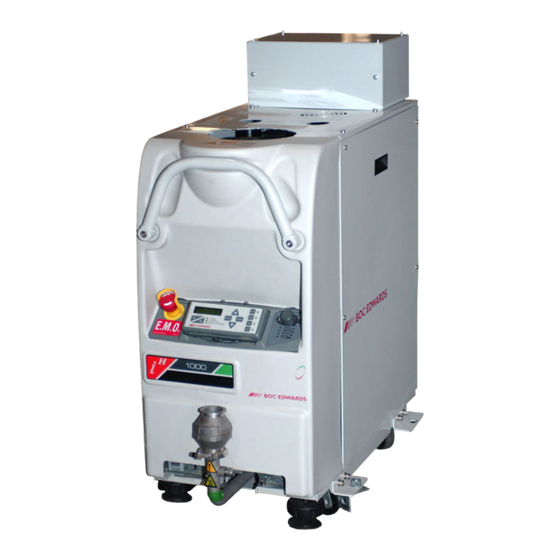
- Page 9 8.5.10 iH Pump Display Terminal Extension Cables 8.5.11 iH Disconnect Box 8.5.12 iH Photohelic Switch/Gauge Kit RETURN OF BOC EDWARDS EQUIPMENT Illustrations Figure Title Page The iH system (iH1000 shown, with side panels removed) Schematic diagram of the HCDP pump gas system...
- Page 10 Illustrations (continued) Figure Title Page Centres of mass dimensions (mm) and mass distribution Typical pumping speed and pump power curves for an iH80 Typical pumping speed and pump power curves for an iH600 at 50Hz 2-10 Typical pumping speed and pump power curves for an iH600 at 60Hz 2-11 Typical pumping speed and pump power curves for an iH1000 at 50Hz 2-12...
- Page 11 Illustrations (continued) Figure Title Page Fit insulation jackets Clean the exhaust check-valve Try to turn the HCDP pump 6-18 System lockout/tagout procedures 6-19 Tables Table Title Page Safety sensors 1-22 Technical data Full load current ratings 2-15 Nitrogen purge flow rates: high gas configuration 2-16 Electrics box default setpoints 2-17...
- Page 12 viii iH Dry Pumping System...
-
Page 13: Introduction
Pa). NOTICE The content of this manual may change from time to time without notice. BOC Edwards accepts no liability for any errors that may appear in this manual nor does it make any expressed or implied warranties regarding the content. So far as is reasonably practicable BOC Edwards has ensured that its products have been designed and constructed so as to be safe and without risks when properly installed and used in accordance with BOC Edwards operating instructions. - Page 14 The following symbols may appear on the iH system: Warning - refer to manual Warning - heavy object Warning - risk of electric shock Warning - moving parts present Warning - hot surfaces Warning - use protective equipment Warning - static sensitive devices PE -Protective earth (ground) RF earth (ground) Warning - risk of catastrophic failure...
-
Page 15: Atex Directive Implications
(LEL). For further information, please contact BOC Edwards: refer to the Addresses page at the end of •... -
Page 16: The Ih System
The iH system The iH system operates at pressures between atmospheric and ultimate vacuum with no lubricating or sealing fluid in the pumping chamber(s). This ensures a clean pumping system without back-migration of oil into the system being evacuated. The iH80 system has an HCDP80 dry pump; the iH600 system has an HCDP80 dry pump, with an HCMB600 mechanical booster pump fitted to the inlet of the HCDP80 pump;... -
Page 17: Safety
Potential hazards on the iH system include electricity, hot surfaces, process chemicals, Fomblin oil and nitrogen and water under pressure. Detailed safety information is given in Section 3.1 (Installation), Section 6.1 (Maintenance) and BOC Edwards publication no. P300-20-000 ‘Vacuum pump and vacuum system safety’. -
Page 18: The Hcmb Mechanical Booster Pump (Ih600/Ih1000 Only)
The 3/4-interstage purge and 2/3-interstage purge flows are switched on and off by the solenoid-valves (17 and 18). The inlet-purge, shaft-seals purge and exhaust-purge flows are switched on and off by the solenoid-valves (22, 19 and 24). The 2/3-interstage and 3/4-interstage purges solenoid-valve (21) operates in conjunction with the inlet-purge solenoid-valve (22), to provide reduced interstage purge flow when inlet-purge is switched Variable restrictors (12 to 16 and 20) limit the purge flow rates. - Page 19 Inlet Nitrogen pressure regulator Elbow Pump Display Terminal HCMB oil filler-plug * NW40 trapped ‘O’ ring Inverter enclosure Emergency stop switch NW40 clamping ring HCMB pump-motor * HCMB pump * Elbow insulation jacket Outlet HCMB oil-level sight-glass * Clamps insulation jacket Gas Module Check-valve Exhaust pipe insulation...
-
Page 20: Temperature Control System
Temperature control system 1.8.1 HCDP pump temperature control system The headplate and the fourth stage of the HCDP pump have a direct cooling system in which water flows around these parts of the pump. All other stages of the pump are air-cooled by natural convection and radiation. -
Page 21: Schematic Diagram Of The Hcdp Pump Gas System
Two-way gearbox vent-valve Variable restrictor (shaft-seals purge) Gearbox vent pipeline Variable restrictor (exhaust-purge) Exhaust-purge pipeline Solenoid-valve (3/4-interstage purge) HCDP pump Solenoid-valve (2/3-interstage purge) 3/4-interstage purge pipeline Solenoid-valve (shaft-seals purge) 2/3-interstage purge pipeline Variable restrictor (2/3 and 3/4-interstage purges) Inlet-purge pipeline Solenoid-valve (2/3 and 3/4-interstage purges) Shaft-seals purge pipeline Solenoid-valve (inlet-purge) -
Page 22: Hcmb Pump Temperature Control System (Ih600/Ih1000 Only)
1.8.2 HCMB pump temperature control system (iH600/iH1000 only) The HCMB600 pump in an iH600 system is cooled by ambient air. The pump-motor is cooled by water which flows through a cooling jacket which surrounds the pump-motor. The pump-motor cooling-water supply and return pipelines are connected to the cooling-water manifold on the HCDP pump. -
Page 23: Electrical System
1.10 Electrical system Refer to Figures 1-3 and 1-4 which show schematic diagrams of the electrical and control systems of the iH80, iH600 and iH1000 systems. 1.10.1 Introduction Refer to Figures 1-3 and 1-4. The iH system has an Electrics Box (1), Electronics Module (3), a Gas Module (2) and a Pump Display Terminal (4). -
Page 24: Schematic Diagram Of The Ih80/Ih600 Electrical Systems
This fuse protects the iH Interface Module (if fitted). Refer to detail E. Fuses inside the Electrics Box (16 to 21) protect the internal circuits of the Electrics Box. Note that you cannot change these fuses; a BOC Edwards service engineer must change these fuses. - Page 25 Figure 1-3 - Schematic diagram of the iH80/iH600 electrical systems iH Dry Pumping Systems 1-13...
-
Page 26: Schematic Diagram Of The Ih1000 Electrical System
RF earth (ground) stud (6) If required, use this to make additional RF earth (ground) connections: refer to Section 3.16.4. Refer to Figure 1-6, detail A or B. The bottom panel of the Electrics Box has the following cables and connectors: Electrics and Control Loom (17) This is used to provide power, measurement signals and control signals to the Electronics Module. - Page 27 Figure 1-4 - iH Dry Pumping Systems 1-15...
-
Page 28: Electronics Module
HCMB thermistor cable (21) On an iH600/iH1000 system, this is used to connect the output of the thermistor in the HCMB pump to the Electrics Box. HCMB electrical supply cable (22) On an iH600/iH1000 system, this is used to connect the electrical supply from the Electrics Box to the HCMB pump. - Page 29 Rear cover Fuse F6 Cooling-water outlet Fuse F5 Cooling-water inlet Fuse F4 Nitrogen inlet Fuse F1 Position of Active Gauge connector Fuse F2 RF earth (ground) stud Fuse F3 Power on lamp iTIM connector Tool Interface Module connector LON interface connector Electrical supply connector Protective earth (ground) stud Exhaust Gas Management interface...
-
Page 30: Controls And Indicators
1.11 Controls and indicators Refer to Figure 1-7. The controls and indicators on the dashboard of the iH system are as follows: Emergency stop switch (1) Press this to immediately shut down the iH system in an emergency: refer to Section 5.12. Pump Display Terminal (2) Use this to control the iH system: refer to Section 1.13. - Page 31 Figure 1-6 - Electrical components (shown without enclosure for clarity) iH Dry Pumping Systems 1-19...
-
Page 32: Control Functions
1.12 Control functions 1.12.1 Priority of control The iH system can be controlled by a number of modules: the Pump Display Terminal (see Section 1.13); an iH Interface Module (see Section 8.5.3); or the iH Single Equipment Monitor (see Section 8.5.4). Only one module can have control of the iH system at any one time. That is, once a module has control of the iH system, control requests from another Module are denied. -
Page 33: Setpoints, Warning And Alarm Conditions
Note that when you first switch-on the electrical supply, no Module will initially have control of the iH system. The Module which you want to control the iH system must take control as described above. 1.12.2 Setpoints, warning and alarm conditions Note: Sensors which generate alarm and warning messages are not safety sensors: see Section 1.12.3. -
Page 34: Safety Sensors
1.12.3 Safety sensors The iH system has a number of safety sensors, which are connected to the relay interlock circuit. If any of the safety sensors cause the interlock relay to operate, the iH system is immediately shut down. The iH system can also be fitted with a photohelic switch accessory. If it operates, all electrical power to the iH system is removed via the disconnect box. - Page 35 As supplied the first page of Normal display shows HCDP pump power consumption and HCDP pump body temperature, and the second page shows HCMB pump power consumption and HCMB pump-motor temperature. You can change the information shown on the Normal display: refer to Section 5.4. At any time, you can press one of the four menu buttons (7) to select a new menu.
-
Page 36: Front Panel Of The Pump Display Terminal
The status LEDs (9) show the current status of the iH system and the Pump Display Terminal: LED colour Meaning ALARM This LED shows when an alarm condition exists. WARNING Amber This LED shows when a warning condition exists. LOCAL Green This LED is on when the Pump Display Terminal has control of the iH CONTROL... -
Page 37: Drip Tray
1.14 Drip tray The drip tray is fitted to the bottom of the iH frame (see Figure 1-1) and allows the collection of potentially spilled liquids from the iH system, thereby satisfying SEMI S2 requirements. 1.15 Seismic brackets The four seismic brackets, which are also used to secure the iH system to a pallet during transit (see Figure 3-1), are fitted to the side of the iH frame. -
Page 38: Ih Disconnect Box (Accessory)
1.18 iH Disconnect box (accessory) The iH disconnect box accessory is used to energise and isolate the power supply to the iH system. It also allows the isolation of the electrical supply during emergency, and for maintenance and troubleshooting the system, thereby satisfying SEMI S2 requirements. Refer to Section 8 for ordering information. - Page 39 AW/6179/A iH Dry Pumping System 1-27...
-
Page 40: Label Positions On Ih System Enclosures
Figure 1-11 - Label positions on iH system enclosures 1-28 iH Dry Pumping System... - Page 41 iH80 iH600 iH1000 Warning! Moving Parts Present External Protective Earth Conductor symbol Voltage variant O < 100 PSIG (< 6.9 bar) Caution! Heavy Object 20-100 PSIG (1.4-6.9 bar) Warning! Hazardous Chemicals Enclosed Warning! Switch off before disconnecting Warning! Disconnect mains supply before ETL Listing Label removing Electric Box covers Caution! Hot Surface...
-
Page 42: Start Control
1.18.1 Start control The disconnect box has a DRY PUMP POWER ON/RESET push button for operational control of the iH system power supply. 1.18.2 Emergency off control If an emergency condition arises, the pump system can be shut down in two ways: red EMERGENCY OFF button located on the control panel, or: EMO signal through 6-way XLR connector from the pump. -
Page 43: Technical Data
TECHNICAL DATA Notes: Unless otherwise specified, data in the following sections applies to all models of iH system. General Dimensions See Figures 2-1 to 2-4 Inlet and outlet See Table 2-1 Warm-up time to nominal pumping performance 15 min Minimum warm-up time to process gas pumping 4 hours Vacuum system maximum leak-rate 1 x 10... - Page 44 Parameter Units iH80 iH600 iH1000 50 Hz m Typical peak pumping speed 60 Hz m 1000 mbar 3 x 10 2 x 10 2 x 10 50 Hz 2 x 10 2 x 10 Typical ultimate vacuum with shaft-seals purge only mbar 1 x 10 7 x 10...
- Page 45 Side view Inlet Plan view Outlet (as supplied) Outlet Dimensions Air-extraction port Figure 2-1 - iH80 dimensions (mm) iH Dry Pumping Systems...
- Page 46 Side view Inlet Plan view Outlet (as supplied) Air-extraction port Figure 2-2 - iH600 dimensions (mm) iH Dry Pumping Systems...
- Page 47 Side view Inlet Air-extraction port Plan view Outlet (as supplied) Inverter enclosure Figure 2-3 - iH1000 dimensions (mm) iH Dry Pumping Systems...
- Page 48 As supplied Cooling-water outlet (as supplied) Alternative positions Cooling-water inlet (as supplied) Nitrogen inlet (as supplied) Cooling-water outlet (alternative position) Cooling-water inlet (alternative position) Nitrogen inlet (alternative position) Figure 2-4 - Services connections dimensions (mm) iH Dry Pumping System...
-
Page 49: Cooling-Water Supply
Cooling-water supply Notes. Use treated water or non-corrosive industrial water to cool the iH system. Maximum supply pressure 100 psig (6.9 bar, 6.9 x 10 Typical pressure differential across supply and return * iH80 15 psi (1.03 bar, 1.03 x 10 iH600/iH1000 15 psi (1.03 bar, 1.03 x 10 Minimum flow rate required for... -
Page 50: Centres Of Mass Dimensions (Mm) And Mass Distribution
iH80 Mass distribution on levelling-feet iH600 iH1000 iH80 75 kg 66 kg 51 kg 48 kg iH600 103 kg 119 kg 75 kg 118 kg Levelling-foot Levelling-foot iH1000 118 kg 115 kg 90 kg 107 kg Levelling-foot Levelling-foot Centre of mass Figure 2-5 - Centres of mass dimensions (mm) and mass distribution iH Dry Pumping Systems... -
Page 51: Typical Pumping Speed And Pump Power Curves For An Ih80
1. 60Hz 2. 50Hz Figure 2-6 - Typical pumping speed and pump power curves for an iH80 iH Dry Pumping Systems... -
Page 52: Typical Pumping Speed And Pump Power Curves For An Ih600 At 50Hz
Note: Discontinuity in curves are as a result of the HCMB pressure relief valve opening and closing Figure 2-7 - Typical pumping speed and pump power curves for an iH600 at 50Hz 2-10 iH Dry Pumping Systems... -
Page 53: Typical Pumping Speed And Pump Power Curves For An Ih600 At 60Hz
Note: Discontinuity in curves are as a result of the HCMB pressure relief valve opening and closing Figure 2-8 - Typical pumping speed and pump power curves for an iH600 at 60Hz iH Dry Pumping Systems 2-11... -
Page 54: Typical Pumping Speed And Pump Power Curves For An Ih1000 At 50Hz
Note: Discontinuity in curves are as a result of the HCMB pressure relief valve opening and closing Figure 2-9 - Typical pumping speed and pump power curves for an iH1000 at 50Hz 2-12 iH Dry Pumping System... -
Page 55: Typical Pumping Speed And Pump Power Curves For An Ih1000 At 60Hz
Note: Discontinuity in curves are as a result of the HCMB pressure relief valve opening and closing Figure 2-10 - Typical pumping speed and pump power curves for an iH1000 at 60Hz iH Dry Pumping System 2-13... -
Page 56: Lubrication
Lubrication Note: BOC Edwards Material Safety Data Sheets for the oils referenced in the following sections are available on request. (Refer to Section 1.1 for contacts). 2.5.1 HCDP pump Gearbox Oil charge 0.75 litres (typical) Grade of oil SAE 40... -
Page 57: Gas System
200-208 V 200-208 V 230 V 380-415 V 460 V Supply voltage and frequency ® 50 Hz 60 Hz 60 Hz 50 Hz 60 Hz Full load (A) 14.4 14.9 14.4 HCDP motor rating (kW) iH80 Maximum power input 3.65 4.48 4.48 3.65... -
Page 58: Materials In Contact With Process Gases
Flow rates Purge flows Pa.ls 2/3-interstage purge * 8.44 x 10 3/4-interstage purge * 5.06 x 10 Typical nitrogen flow Shaft-seals purge 6.76 x 10 rates Exhaust-purge 8.44 x 10 (high gas Maximum total flow without inlet-purge 7.44 x 10 configuration: factory set) Inlet-purge... -
Page 59: Resource Conservation
2.10 Resource conservation Measures have been taken in the design of the iH system to conserve the environment, as advised by ISO14001 - Environmental management systems. Packaging materials may be recycled. Power consumption has been minimised. Lubrication for life has been incorporated into the pump design. No pump parts require cleaning for maintenance. -
Page 60: Connections
Default setpoint values Parameter Unit High High alarm warning warning alarm Shaft-seals purge on, Exhaust-purge on, 2/3-interstage purge off, 3/4-interstage purge off, Inlet-purge off Total nitrogen Shaft-seal purge on, flow Exhaust-purge on, (high gas 38.0 59.4 2/3-interstage purge on, configuration: 3/4-interstage purge on, Inlet-purge off factory set) -
Page 61: Tracer Gas Analysis
2.13 Tracer gas analysis IH600 pumping system tracer gas test results are as follows (see Tables 2-7 through 2-8): Note that because the iH600 has the largest iH enclosure size, these results qualify the iH80 and iH1000 enclosures. Test Parameters Tracer gas Tracer gas concentration 4.00%... -
Page 62: Disconnect Box (Accessory)
2.14 Disconnect box (accessory) 2.14.1 General Dimensions: 406mm (16.0”) x 305mm (12.0”) x 203mm (8.0”) Mass: 17kg (38.0lbs) 2.14.2 Operating conditions Temperature Range Operating: +10°C to +40°C (+50°F to +104°F) Storage: -45°C to +55°C (-113°F to + 131°F) Relative Humidity: 10% to 90% Maximum Operating Altitude: 2000m 2.14.3 Electrical data... -
Page 63: Installation
If you do not, you can cause injury to people and damage to equipment. Only BOC Edwards engineers may install the iH pump series. Users can be trained by BOC • Edwards to conduct the tasks described in this manual, contact your local service centre or BOC Edwards for more information. -
Page 64: Installation Checklist
Installation checklist The operations required to install the iH system and the sections of this instruction manual which describe those operations are shown in Table 3-1. Installation operation Section Unpack and inspect Remove the enclosure panels Reconfigure the nitrogen and water connections (if required) Locate the iH system Check the pump oil-level(s) iH80 systems... -
Page 65: Unpack And Inspect
Mounting 3.21.2 Electrical Installation 3.21.3 Main Electrical Supply 3.21.4 Cable Connections 3.21.5 Install Photohelic Switch/Gauge (accessory) 3.22 Unpack and Inspect 3.22.1 Mounting 3.22.2 Piping Connections 3.22.3 Cable Connections 3.22.4 Table 3-1 - Installation checklist (...continued) Unpack and inspect WARNING You must use suitable lifting equipment to move the iH system. It is too heavy to lift by hand. - Page 66 Use the following procedure to unpack and inspect the iH system. 1. Place the pallet in a convenient position with a fork-lift truck or a pallet truck. 2. Remove the staples which secure the cardboard box to the pallet, then remove the cardboard box.
-
Page 67: Remove The Enclosure Panels
iH system Seismic Bracket Nut and washer Cap-head screw and washer Stud Levelling foot Block Pallet Figure 3-1 - Remove the iH system from the pallet Remove the enclosure panels 1. Refer to Figure 3-3. 2. Remove the right-hand side panel from the iH system: Place your hand against the top of the right-hand side panel (4) to support it and use a •... - Page 68 iH80 iH600 iH1000 Lifting-bolts Inverter enclosure (iH1000 only) Figure 3-2 - Lifting-bolt positions iH Dry Pumping Systems...
-
Page 69: Reconfigure The Nitrogen And/Or Water Connections (If Required)
Reconfigure the nitrogen and/or water connections (if required) CAUTION Ensure that the cooling-water system of your iH system is correctly configured for your electrical supply frequency. If it is incorrectly set at 50Hz, the system will run above optimum operating temperature. If it is incorrectly set at 60Hz, the system will run below optimum operating temperature. - Page 70 iH600/iH1000 iH80 Top panel Catches (on rear of item 1) Catches Right-hand side panel Pins Screws (2 off) Lower cover Inverter enclosure (iH1000 only) Handle Figure 3-3 - Remove/refit the enclosure panels iH Dry Pumping Systems...
-
Page 71: Check The Pump Oil-Level(S)
2. Wheel the iH system on its castors to move it into its operating position. 3. Adjust the levelling feet to make sure that the iH system is level and is not supported by the castors. 4. If you want to secure the iH in place to prevent inadvertent movement (for example, during an earthquake), take note of the following the iH system can be secured to the floor by fitting suitable bolts or studs (not supplied) •... - Page 72 HCDP headplate manifold Control Plug Blanking Plug Figure 3-4 - HCDP headplate cooling - water manifold (as supplied) 3-10 iH Dry Pumping Systems...
-
Page 73: Ih600/Ih1000 Systems
3.7.2 iH600/iH1000 systems The iH600 and iH1000 systems are supplied with both the HCDP and HCMB pumps filled with oil. However, we recommend that you check the HCDP and HCMB oil-levels as described below. 1. Check the HCDP pump oil-level: refer to Section 3.7.1. 2. -
Page 74: Connect The Ih Inlet To Your Vacuum System
Incorporate flexible pipelines in the vacuum pipeline to reduce the transmission of vibration • and to prevent loading of coupling-joints. We recommend that you use BOC Edwards braided flexible pipelines. Adequately support vacuum pipelines to prevent the transmission of stress to pipeline •... - Page 75 Figure 3-5 - System arrangement to reduce effective footprint (if required) iH Dry Pumping Systems 3-13...
-
Page 76: Connect The Ih Exhaust Outlet To Your Exhaust-Extraction System
Incorporate flexible pipelines in the exhaust pipeline to reduce the transmission of vibration • and to prevent loading of coupling-joints. We recommend that you use BOC Edwards braided flexible pipelines. You must be able to isolate the exhaust-outlet from the atmosphere if you have pumped or •... -
Page 77: Connect To Your Factory Extraction System (Optional)
Use the following procedure to connect the iH system to your exhaust-extraction system: refer to Figure 1-1. 1. If the check valve (18) is not required on your application: remove the exhaust enclosure (26) by removing the screws connecting to the rear •... -
Page 78: Connect The Nitrogen Supply
Note: If you need further information on leak testing, contact your supplier or BOC Edwards for advice. Leak-test the system after installation and seal any leaks found. Dangerous substances which leak from the system will be dangerous to people and there may be a danger of explosion if air leaks into the system. - Page 79 Remove the blanking panel Fit the Pump Display Terminal Blanking panel Recess Dashboard Pump Display Terminal connector Pump Display Module connector Cable Connector Pump Display Terminal Viewing angle adjuster Figure 3-6 - Fit the pump display terminal iH Dry Pumping Systems 3-17...
-
Page 80: Install Additional Safety Equipment (Optional)
3.14 Install additional safety equipment (optional) WARNING If your Process Tool/control system needs to know the total flow rate of nitrogen to the iH system for safety reasons, install suitable measurement equipment in the nitrogen supply pipeline. WARNING If you use the nitrogen purges to dilute dangerous gases to a safe level, ensure that the system shuts down if the nitrogen supply to the iH system fails. - Page 81 iH80 Inlet spool piece HCMB pump iH600/iH1000 Leak-test port (blanked) Leak-test port (blanked) HCDP pump Support manifold Figure 3-7 - Leak-test port positions iH Dry Pumping Systems 3-19...
-
Page 82: Connect To Your Emergency Stop Circuit (Optional)
3.15 Connect to your emergency stop circuit (optional) Note: If you do not connect to your own control equipment, you must fit the iH Tool Interface Module plug supplied to the iH Tool Interface Module connector on the rear of the iH system (Figure 1-5, item 8). -
Page 83: Reconfigure The Ih System For Your Electrical Supply (Ih80/Ih600 Only)
iH80 system Electrics Box iH600 system Cover Screw Common cable Voltage select cable Terminal-block Figure 3-8 - Reconfigure the iH system for your electrical supply (iH80/iH600 only) iH Dry Pumping Systems 3-21... -
Page 84: Electrical Supply And Rf Earth (Ground) Connections
You cannot reconfigure an iH1000 system. If you want to use an iH1000 system with a different electrical supply to that specified on the rating plate (Figure 3-9, item1), contact your supplier or BOC Edwards. CAUTION Ensure that the cooling-water system of your iH system is correctly configured for your electrical supply frequency. -
Page 85: Reconfigure The Pump-Motor Terminal-Boxes (Ih80/Ih600 Only)
iH80 system iH600 system High voltage configuration Low voltage configuration Rating plate (on Electrics Box) Pump-motor terminal-box cover Screws (4 off) Blanking plate Screws (6 off) Electrics Box Screws (4 off) Pump-motor terminal-box Links Figure 3-9 - Reconfigure the pump-motor terminal-boxes (iH80/iH600 only) iH Dry Pumping Systems 3-23... -
Page 86: Reconfigure The Pump(S) For Your Electrical Supply (If Necessary)
You cannot reconfigure an iH1000 system. If you want to use an iH1000 system with a different electrical supply to that specified on the rating plate (Figure 3-9, item 1), contact your supplier or BOC Edwards. CAUTION Ensure that the cooling-water system of your iH system is correctly configured for your electrical supply frequency. -
Page 87: Connect The Electrical Supply Cable To The Connector Mating-Half
iH80 Pin 1 (phase 1) Electrical supply cable iH600 Pin 2 (phase 2) Cover iH1000 Pin 3 (phase 3) Connector block Earth (ground) screw Electrical supply connector Strain relief bush 10. Electrics Box Figure 3-10 - Connect the electrical supply cable to the connector mating-half iH Dry Pumping Systems 3-25... -
Page 88: Connect The Electrical Supply To The Ih System
8. Undo and remove the four screws (3) which secure the cover (2) to the HCMB pump-motor terminal-box, then remove the cover (through the access hole in the rear cover-plate). 9. Look at the links in the terminal-box (8): For high voltage operation (380-415 V at 50 Hz or 460 V at 60 Hz), ensure that the links (9) •... -
Page 89: Connect An Additional Rf Earth (Optional)
Notes: On an iH1000 system, the earth (ground) installation must ensure that there is an equipotential zone around the iH system: the voltage between the protective earth (ground) stud on the iH system and any other conducting surface within 2 metres of the iH system must be < 30 V r.m.s. If you connect the electrical supply to an iH1000 system through ELCB relays, they must be suitable for the protection of equipment with a d.c. -
Page 90: Refit The Enclosure Panels
Connect an additional earth (ground) cable to the M6 RF earth (ground) stud. You must use a • suitable low-impedance cable (for example, use braided cable). 3.17 Refit the enclosure panels 1. Refer to Figure 3-3. Refit the right hand and left hand side panels use the following method for each side panel. -
Page 91: Adjust The Interstage Purge Flow Rates If Necessary
3.19 Adjust the interstage purge flow rates if necessary The 2/3-interstage purge and 3/4-interstage purge flow rates are preset for correct operation. If necessary, these purge flow rates can be adjusted: contact your supplier or BOC Edwards for advice. 3.20... -
Page 92: Configure And Switch On An Ih600 System
You can only switch on and configure an iH600 system if you have a Single Equipment Monitor (SEM) connected to the iH system. If you do not have SEM, do not use the following procedure; contact your supplier or BOC Edwards for advice. CAUTION Do not operate an iH600 system with the maximum inlet pressure for longer than the maximum time specified in Table 2-1. - Page 93 When you switch on an iH600 system, the HCDP pump starts immediately, but there is a delay before the HCMB pump is started. This ensures that the vacuum system and vacuum inlet pipelines are partially evacuated by the HCDP pump, so that the maximum inlet pressure for the HCMB pump is not exceeded (see Section 2).
-
Page 94: Install The Disconnect Box (Accessory)
12. If the required booster start delay is greater than 30 seconds, use the SEM to edit and save the original configuration set uploaded from the iH (the set saved as, for example, "iH600"): set the BOOSTER START DELAY to the required booster start delay time. 13. -
Page 95: Mounting
3.21.2 Mounting The disconnect box is a wall mount unit which utilises the four mounting holes on the back wall of the box. Height requirements for the mounting box are shown in Figure 3-11. Note: The Disconnect box must be mounted in close proximity to the iH system. Minimum mount height to bottom of reset push button Maximum mount height to top of disconnect switch Figure 3-11 - Disconnect box mounting height requirements... -
Page 96: Main Electrical Supply
Figure 3-12 - Disconnect box electrical schematic 3.21.4 Main electrical supply Connect the power supply to the disconnect box using the following steps: 1. Punch out the power supply inlet hole plug on the top of the disconnect box. 2. Tie in the customer power to the supply side of the fused mains disconnect as shown in Figure 3-13. -
Page 97: Cable Connections
3.21.5 Cable connections Connect the cables from the disconnect box to the appropriate locations as follows: 1. Punch out the EMO cable outlet hole (2) on the bottom of the disconnect box. See Figure 3-14. 2. Connect the cable cores to terminals 1 and 2 of the disconnect box. See Figures 3-12 and 3-13. 3. - Page 98 Figure 3-13 - Disconnect box sub-panel general arrangement 3-36 iH Dry Pumping Systems...
- Page 99 Customer supply: 1.36 inch diameter hole EMO cable Dry pump power Photohelic gauge signal cable Photohelic power cable Figure 3-14 - Disconnect box cable connections iH Dry Pumping Systems 3-37...
-
Page 100: Install Photohelic Switch/Gauge (Accessory)
3.22 Install photohelic switch/gauge (accessory) The following sections provide the installation of the photohelic switch/gauge to your system. Note that the installation of the photohelic gauge is only possible if the disconnect box has been installed. 3.22.1 Unpack and inspect Remove all packaging materials and protective covers and check the switch/gauge. -
Page 101: Piping Connections
3.22.3 Piping connections Connect the piping between the photohelic switch/gauge and the iH exhaust enclosure using the following steps: 1. Connect the male connector to the photohelic monitoring port on the photohelic spoolpiece (Figure 3-15, item 2). Refer to Section 6.2 for guidelines. 2. -
Page 102: Cable Connections
Male connector and gasket Braided hose Elbow union Male adapter Male elbow Reference tube Figure 3-16 - Photohelic gauge piping connections 3.22.4 Cable connections Connect the cabling between the photohelic switch/gauge and the disconnect box as follows: 1. Using a flat screwdriver, open the disconnect door by turning the lock. 2. -
Page 103: Pump Display Terminal Menus And Display Formats
PUMP DISPLAY TERMINAL MENUS AND DISPLAY FORMATS Introduction The menus used and the display messages shown on the Pump Display Terminal are described in the menu diagrams in Figures 4-2 to 4-19. The following symbols and conventions are used in the menu diagrams: These are flow lines. -
Page 104: General Operation
General operation When you first switch on the iH system, the normal display is shown: see Figure 4-5. Refer to Figure 4-1. You can then press the On or Off button (1 or 10) or any of the four menu buttons (7) to enter the corresponding menu. -
Page 105: Display Text And Variable Text
Other specific uses of the CANCEL button are as follows: In the Switch On and Switch Off menus (Figures 4-3 and 4-4), when you press CANCEL, the • menu is exited and the normal display is shown. In the Status menu (Figure 4-6), when you press CANCEL the display shows the first two •... -
Page 106: Wrap-Around
Wrap-around When you use the up and down buttons to change a digit or character on the display, the digit or character will 'wrap-around' between its minimum and maximum values. For example, when you enter a password digit, if the digit is '0' and you press the down button, the digit will change to '9';... -
Page 107: Menu Structure
8. Press the ENTER button; the display will then show 'Pressure' on the top line and the currently selected pressure units on the bottom line. 9. Press the up or down buttons to change the units displayed to the required units, then press the ENTER button. -
Page 108: Menu Logic
From any menu <Any display on the Pump Display Terminal> Normal Normal [4-5] Status Status [4-6] Control Control [4-7] Setup Setup [4-8] Switch on [4-3] If the Pump Display Terminal does not have control when you try to switch on or switch off the Switch off [4-4] pumping system, an... -
Page 109: Switch On Menu
Switch on SELECT PUMP ENTER Process pump SELECT PUMP Only available if you ENTER Load lock pump have an iH Interface Module fitted with an Auxiliary Interface Card connected to the iH system. SELECT PUMP Only available if you ENTER L/Lock + Process have an iH Interface Module fitted with an... -
Page 110: Switch Off Menu
Switch off Single pump ENTER Pump off menu (that is, no CANCEL Clears load-lock pump connected). ENTER SELECT PUMP ENTER Multi pump Process pump menu (that is, a load-lock pump is connected). SELECT PUMP Only available if you have ENTER Load lock pump an iH Interface Module fitted with an Auxiliary... -
Page 111: Normal Menu
Normal DD.D kW First page of the normal display DP BODY DD.D C DD.D kW Second page of the normal display MB TEMP DD.D C To change the information shown on the two pages, refer to Section 5. Figure 4-5 - Normal menu iH Dry Pumping Systems... -
Page 112: Status Menu
Status Last parameter [4-6/2] DD.D A DP POWER DD.D kW On iH80 systems, <NP> will DD.D A be shown instead of values. MB POWER DD.D kW RUN HOURS DDD H PROCESS PROCESS CYCLES MB TEMP DDD.D C On iH80 systems, <NP> will DP MOTOR DDD.D C be shown instead of an... - Page 113 Figure 4-6 - Status menu: sheet 2 of 2 iH Dry Pumping Systems 4-11...
-
Page 114: Control Menu
Control Release control < ENTER Normal [4-5] Take control Release control ENTER Normal [4-5] Take control < Figure 4-7 - Control menu 4-12 iH Dry Pumping Systems... -
Page 115: Setup
Select option entered, continue to select the [4-12/2] service menu option: the service password is only available to BOC Edwards service engineers. Normal [4-5] If the password was incorrect, revert to normal display Figure 4-8 - Setup menu: sheet 1 of 3... -
Page 116: Inlet Purge
Select option Last option [4-8/3] [4-16/3] SETUP MENU ENTER Inlet purge Turn on/off [4-16/3] SETUP MENU ENTER Gas Ballast Turn on/off [4-16/2] SETUP MENU ENTER Valve 1 Open/close [4-9] SETUP MENU ENTER Run til crash Run til crash Prev option Next option [4-8/3] [4-8/3]... -
Page 117: Setup Menu
Next option Prev option [4-8/2] [4-10] SETUP MENU ENTER Units Units [4-11] SETUP MENU ENTER Normal Display Normal Display SETUP MENU Service [4-12/1] ENTER Service [4-18] SETUP MENU ENTER Messages Messages Last option Select option [4-8/2] [4-8/2] Figure 4-8 - Setup menu: sheet 3 of 3 iH Dry Pumping Systems 4-15... - Page 118 Run til crash RUN TIL CRASH ENTER RUN TIL CRASH ENTER Exit Return to [4-8/2] Figure 4-9 - Run til crash menu 4-16 iH Dry Pumping Systems...
-
Page 119: Units Menu
Units Press the CANCEL button at any time to exit this menu and return to [4-8/3]. UNITS SELECT Pressure Units ENTER ENTER Pressure <units> Use the up and down buttons to select the new units:PSI or kPa UNITS SELECT Temperature Unit ENTER ENTER Temperature... - Page 120 Normal Display SELECT LINE ENTER Change the first line of Top page 1 page 1 of the Normal Display SELECT LINE Change the second line of ENTER Bottom page 1 page 1 of the Normal Display SELECT LINE Change the first line of ENTER Top page 2 page 2 of the Normal Display...
-
Page 121: Service
Service Use the up and down SERVICE PASSWORD buttons to increase or Password decrease the first digit of the password. Press ENTER when the digit is set correctly. ENTER SERVICE PASSWORD Use the up and down Password buttons to increase or decrease the second digit of the password. -
Page 122: Service Menu
Select option [4-13] SERVICE MENU ENTER Serial Menu Serial Numbers [4-14] SERVICE MENU ENTER Zero sensors Zero Sensors [4-16/1] SERVICE MENU ENTER Manual Manual SERVICE MENU View Status ENTER View status [4-17] [4-15] SERVICE MENU ENTER Gas Valve Control Gas Valve Control Figure 4-12 - Service menu: sheet 2 of 2 4-20 iH Dry Pumping Systems... -
Page 123: Serial Menu
Use this menu to display serial Serial Menu numbers or the user tag. Note that you cannot change these items. Press the CANCEL button at any time to exit the menu and return to [4-12/2] SERIAL MENU DP SYSTEM S/N ENTER DP System S/N <serial no./tag>... -
Page 124: Zero Sensors
Zero sensors ZERO SENSORS Press ENTER ENTER Exit (or CANCEL) to exit menu and return to [4-12/2]. ZERO SENSORS Zero the nitrogen mass ENTER flow transducer. It takes up to 15 minutes to zero the transducer. In this time, the display will timeout to normal display. -
Page 125: Gas Valve Control Menu
Notes: You should only use this menu if you have been suitably trained by BOC Edwards Service Personnel. If necessary, contact BOC Edwards or your supplier to arrange suitable training. The actual values displayed depend on the build standard of your system (as identified by its serial number). -
Page 126: Manual
Manual Last option [4-16/2] [4-16/3] MANUAL MENU ENTER Turn on/off DP Only See notes in Section 5.15 [4-16/3] MANUAL MENU ENTER Turn on/off See notes in Section 5.15 [4-16/3] MANUAL MENU ENTER Turn on/off Load lock pump [4-16/3] MANUAL MENU ENTER Turn on/off Nitrogen Supply... -
Page 127: Manual Menu
Next option Prev option [4-16/1] [4-16/2] MANUAL MENU ENTER Open/close Valve 1 Open/close VALVE D ENTER Open VALVE D ENTER Close Return to Exit above or to [4-8/1] Figure 4-16 - Manual menu: sheet 2 of 3 iH Dry Pumping Systems 4-25... - Page 128 Turn on/off <parameter> ENTER <parameter> is the previously selected device: DP, MB, Load Lock Pump, Nitrogen supply, Gas Ballast or Inlet Purge. <parameter> ENTER Exit Return to [4-8/2] or [4-16/1] Figure 4-16 - Manual menu: sheet 3 of 3 4-26 iH Dry Pumping Systems...
-
Page 129: View Status
View Status Last parameter [4-17/2] DD.D A DP POWER DD.D kW On iH80 systems, <NP> will DD.D A be shown instead of values. MB POWER DD.D kW RUN HOURS DDD H PROCESS PROCESS MB TEMP DDD.D C On iH80 systems, <NP> will DP MOTOR DDD.D C be shown instead of an... - Page 130 Figure 4-17 - View Status menu: sheet 2 of 2 4-28 iH Dry Pumping Systems...
-
Page 131: Messages Menu
Messages MESSAGES ENTER English MESSAGES ENTER Downloaded Exit Return to [4-8/3] Figure 4-18 - Messages menu iH Dry Pumping Systems 4-29... -
Page 132: Warning And Alarm Messages Menu
Wng & Alarm Messages ALARM <e.no> WARNING <e.no> <message> <message> ENTER <message> Display advisory message (if any) <message> ENTER Normal [4-5] Figure 4-19 - Warning and alarm messages menu 4-30 iH Dry Pumping Systems... -
Page 133: Operation
OPERATION Introduction The following sections describe the use of the Pump Display Terminal to operate the iH system. For a description of the use of an Interface Module or Communications Module accessory to operate the iH system, refer to the instruction manual supplied with the Module. For a description of the operation of the load-lock pump (if you have connected the iH system to the load-lock pump through an Interface Module), refer to Section 5.16. -
Page 134: Atex Directive Implications
ATEX directive implications 5.2.1 Introduction This equipment is designed to meet the requirements of Group II Category 3 equipment in accordance with Directive 94/9/EC of the European Parliament and the Council of 23rd March 1994 on the approximation of the laws of the Member States concerning equipment and protective systems intended for use in potentially explosive atmospheres. -
Page 135: Gas Purges
Note: If you download a configuration set to the iH system, a BOC Edwards engineer must adjust the variable restrictors in the gas system (see Section 1.6) to suit the application. Contact your nearest BOC Edwards Service Centre to arrange this. -
Page 136: Change The Display Format
You can use the Single Equipment Monitor to download one of these configuration sets to the iH system. Ensure that you use the correct configuration set for your application; contact your supplier or BOC Edwards for advice before you download a configuration set. Nominal flow rates (slm) -
Page 137: Change The Display Units
5.4.2 Change the display units If required, you can change the Pump Display Terminal display units: Pressures shown on the Pump Display Terminal can be displayed in either kPa or psi. Use the • Setup/Units/Pressure menu to change the pressure display units. Temperatures shown on the Pump Display Terminal can be displayed in either C or F. -
Page 138: Start-Up
Start-up WARNING Do not operate the iH system with any enclosure panels removed and do not touch any parts of the pump(s) when the iH system is on. Surfaces of the pump(s) are very hot and can cause injury to people. WARNING Ensure that it is safe to start the iH system. -
Page 139: Check The Nitrogen Pressure And Adjust If Necessary
The solenoid-valve(s) in the Gas Module will open to switch on the nitrogen supplies to the • HCDP pump. On iH600/iH1000 systems, after the booster start delay, the HCMB pump will be switched on. • Check the nitrogen pressure and adjust if necessary Note: You must only check and adjust the nitrogen pressure after the iH system has been operating for at least four hours, so that the HCDP pump is at its correct operating temperature. -
Page 140: Warning And Alarm Indications
Warning and alarm indications Notes: Refer to Section 6 for a full list of the warning and alarm messages and their meanings. Unless you have changed the corresponding setpoints (see Section 5.3), nitrogen purge flow and pressure warning conditions will occur if an iH80 system is operated for extended periods with the inlet pressure close to atmospheric pressure. -
Page 141: Manual Shut-Down
5.10 Manual shut-down WARNING If you intend to do maintenance on the iH system after you have shut it down and you will not isolate the iH system from the electrical supply, do not disconnect the Pump Display Terminal or release control from the Pump Display Terminal (see Section 5.5). -
Page 142: Warning And Alarm Messages
Sensor data Units Notes HCDP pump current consumption HCDP pump power consumption HCMB pump current consumption * HCMB pump power consumption * Total running time hours Total run-time of the iH system. Process running time hours Total run-time on process. Process cycles Process cycles. -
Page 143: Automatic Shut-Down
If you need to shut down the iH system quickly, use the Fast shut-down option. When you select Fast shut-down, the following actions will occur (with a small time delay between each action): On an iH600 or iH1000 system, the HCMB pump is switched off. •... -
Page 144: Emergency Stop
On an iH600 or iH1000 system, the following alarms will cause only the HCMB pump to shut down, whether 'run til crash' is selected or not: HCMB CURRENT HIGH/LOW * (error numbers 710 and 712). • HCMB THERMISTOR HIGH (error number 912). •... -
Page 145: Restart The Ih System After Emergency Stop Or Automatic Shut-Down
5.14 Restart the iH system after emergency stop or automatic shut-down WARNING If a pump is automatically shut down, ensure that it is safe to restart before you restart the pump. Note: If the iH system has automatically shut down because of high HCDP pump power (alarms 412 and 512), check that the HCDP pump is free to rotate before you restart the iH system: refer to Section 6.17. -
Page 146: Operation Of Ih System Components
5.15 Operation of iH system components WARNING Ensure that it is safe to start the iH system. If you do not (and, for example, maintenance is being performed on components downstream of the iH system), you could cause injury to people. CAUTION On an iH600 system, do not operate the HCMB pump unless the HCDP pump is on and has been operating for longer than the booster start delay. -
Page 147: Operation Of The Load-Lock Pump
5.16 Operation of the load-lock pump Note: Operation of the iH system with high inlet pressure may result in shaft-seal pressure warnings (refer to Table 6-1): the operation of the iH system will not be affected, and you can ignore these warnings. -
Page 148: Shutdown
5.17.3 Shutdown The system can be shutdown in four ways through the disconnect box: local EMO; remote EMO; photohelic gauge in warning state, or; brownout condition over 3 seconds. The following sections describe each of the shutdown methods. 5.17.4 Local EMO Press the EMO push button on the control panel to shut the system down. -
Page 149: Maintenance
MAINTENANCE Safety WARNING Obey the safety instructions given below and take note of appropriate precautions. If you do not, you can cause injury to people and damage to equipment. WARNING Hazardous chemicals are located within the pumps and piping. Use of suitable protective gloves and clothing along with a respirator is recommended if contact with substances is anticipated. -
Page 150: Correct Use Of Tube Fittings
The iH system may have overheated if it was misused, if it malfunctioned or if it was in a fire. BOC Edwards Material Safety Data Sheets for fluorinated materials used in the pump are available on request: contact your supplier or BOC Edwards. (See Section 1.1 for contact... -
Page 151: Fit A Tube Fitting
Tube fitting Front (tapered) ferrule Tube Rear ferrule Figure 6-1 - Fit a tube fitting Tube fitting Front (tapered) ferrule Rear ferrule Tube Figure 6-2 - Retighten a tube fitting iH Dry Pumping Systems... -
Page 152: Reconnect A Tube Fitting
Adjust the frequency of maintenance operations according to your experience. When you maintain the iH system, use BOC Edwards maintenance and service kits. These contain all of the necessary seals and other components necessary to complete maintenance operations successfully. -
Page 153: Check The Purge Gas Flow Rates
Check the purge gas flow rates Use the Service/Gas valve control menu to regularly check the purge gas flow rates against the nominal flow rates shown in Table 5-1. Inspect and clean the exhaust-pipe, elbow and check-valve WARNING The substances which accumulate in the exhaust-pipe, elbow and check-valve can be dangerous. - Page 154 10. Use a hexagonal key to remove the four M8 cap-head screws and washers which secure the exhaust pipe (19) to the HCDP pump, then remove the metal 'O' ring and the exhaust-pipe from the HCDP pump. Dispose of the 'O' metal ring. 11.
-
Page 155: Clean And Refit The Check-Valve (If Fitted)
Exhaust pipe insulation jacket Elbow Support bracket assembly Elbow insulation jacket Insulation jacket tab Clamps insulation jacket Exhaust pipe Plastic wing nut NW40 clamp Figure 6-3 - Fit insulation jackets 6.6.2 Clean and refit the check-valve (if fitted) Note: This requires a check valve service kit. Refer to Section 8.3. Refer to Figure 6-4. - Page 156 Inlet-flange Spider leg 'O' ring Valve body (female) Flow direction arrow Fluoroelastomer ball*/ Outlet-flange Perfluoroelastomer (Fluorine resistant) ball* Valve body (male) The ball in check valve could be either of these materials Figure 6-4 - Clean the exhaust check-valve iH Dry Pumping Systems...
-
Page 157: Check The Hcmb Pump Oil-Level (Ih600/Ih1000 Only)
If there is a significant loss of oil from the pump, the shaft-seals may have failed. You cannot replace the shaft-seal. Contact your supplier or a BOC Edwards Service Centre for advice. Use the following procedure to check the oil-level. -
Page 158: Check The Hcdp Pump Oil-Level
3. Refer to Figure 1-1. Check that the oil-level is between the MAX and MIN marks on the bezel of the HCMB oil-level sight-glass (5): If the oil-level is above the MAX mark, drain excess oil from the pump as described in •... -
Page 159: Change The Hcdp Pump Oil
3. Refer to Figure 1-1. Check that the oil-level is between the MAX and MIN marks on the bezel of the HCDP oil-level sight-glass (11): If the oil-level is above the MAX mark, drain excess oil from the pump as described in •... -
Page 160: Change The Hcmb Pump Oil (Ih600/Ih1000 Only)
4. Use a suitable pump or syringe to suck the oil out of the pump. 5. Dispose of the old 'O' ring on the oil filler-plug (8) and replace it with a new 'O' ring (available as a spare: refer to Section 8.3). 6. -
Page 161: Zero The Gas Module Flow Transducer
1. Shut down the iH system (refer to Section 5.10) and allow it to cool. 2. Remove the right-hand side enclosure panel from the iH system: refer to Section 3.4. 3. Refer to Figure 1-1. Remove the HCMB oil filler-plug (2). 4. -
Page 162: Replace A Fuse
Electrics Box. Note: You can only change the fuses in fuse holders F7, F8 and F9. A BOC Edwards service engineer must change fuses F1 to F6 in the Electrics Box (see Figure 1-5). -
Page 163: Relocate The Ih System For Maintenance
6.15 Relocate the iH system for maintenance WARNING Use suitable lifting equipment to move the iH system. WARNING System process gases and residue can be highly toxic. Take all necessary precautions when handling components that have, or could have, come into contact with them, including ‘O’... -
Page 164: Check For Free Rotation Of The Hcdp Pump
If the shaft is free to turn, remove the hexagonal key and continue at Step 5. • If the shaft is not free to turn, contact your supplier or BOC Edwards: do not try to restart • the iH system. -
Page 165: Fault Finding
6.17 Fault finding WARNING Only personnel specially trained to perform electrical maintenance should attempt troubleshooting inside electrical enclosures. These enclosures contain hazardous voltages and are not operator areas. Before performing any maintenance or trouble shooting it is recommended that you follow the lockout/tagout procedures according to the Control of Hazardous Energy (Lockout/Tagout) in Volume 29 of the Code of Federal Regulation (29CFR) Section 1910.147 for the customer supply. - Page 166 iH80 Rear cover iH600 Plug and 'O' ring: iH1000 Correct direction of rotation arrow Figure 6-5 - Try to turn the HCDP pump 6-18 iH Dry Pumping Systems...
-
Page 167: Disconnect Box And Photohelic Switch/Gauge (Accessories)
6.18 Disconnect box and photohelic switch/gauge (accessories) WARNING Only personnel specially trained to perform electrical maintenance should attempt troubleshooting inside electrical enclosures. These enclosures contain hazardous voltages and are not operator areas. Before performing any maintenance or troubleshooting it is recommended that you follow the lockout/tagout procedures according to the Control of Hazardous Energy (Lockout/Tagout) in Volume 29 of the code of federal Regulation (29CFR) section 1910.147 for the customer supply. -
Page 168: Introduction
The disconnect box and photohelic switch/gauge contains no serviceable parts. Repair of faults by the user is limited to replacement of fuses, and resetting of the circuit breakers. If any other repairs are required, contact your supplier or your nearest BOC Edwards Service Centre for advice. -
Page 169: Warning Messages
Warning message Advisory message Meaning/recommended action WARNING (a) there is a fault in the Control SMA, or (b) the emergency stop button has been pressed to shut down the iH system, or (c) there has been a transient electrical supply failure (longer than the hold-up time of the iH power supply). - Page 170 Warning message Advisory message Meaning/recommended action WARNING SEE MANUAL The HCDP motor thermistor Is short circuited. Check the thermistor connections inside the HCDP pump motor terminal-box and check the connections between the HCDP pump and the Electrics Box. WARNING SEE MANUAL There is a phase imbalance in the electrical supply to the HCDP pump.
- Page 171 Warning message Advisory message Meaning/recommended action WARNING 1011 SEE MANUAL There is a phase imbalance in the electrical supply to the HCMB pump. Check the electrical supply and the connections to the iH system. If the electrical supply and connections are correct, the pump motor may be faulty.
- Page 172 Warning message Advisory message Meaning/recommended action WARNING 3913 The exhaust pressure transducer is not fitted, or is disconnected or has failed. Check and rectify as necessary. WARNING 4009 ADJUST REGULATOR The shaft-seals purge pressure is too low. SS PURGE LOW INCREASE PRESS.
- Page 173 Warning message Advisory message Meaning/recommended action WARNING 5513 The HCMB pump-motor surface temperature sensor is not fitted, or is disconnected or has failed. WARNING 5609 EXHAUST TEMP LOW The temperature of the exhaust is too low for EXHAUST TEMP LOW CHECK EXHAUST the process.
-
Page 174: Alarm Messages
Warning message Advisory message Meaning/recommended action WARNING 17601 SEE MANUAL The inverter on an iH1000 system has experienced a transient power supply problem, or there is a recoverable fault. WARNING 17701 SEE MANUAL The HCMB pump stator temperature is > 165 C, and the HCMB pump speed has been reduced to 1200 r.min . - Page 175 10 Hz for more than three minutes. There is a mechanical fault (possible a pump rotor has locked): contact your supplier or BOC Edwards for advice. Table 6-2 - Alarm messages (continued) iH Dry Pumping Systems...
- Page 176 You must manually restart the HCMB pump (refer to section 5.13). If the alarm condition persists after several attempts to restart the HCMB pump, contact your supplier or BOC Edwards for advice. Table 6-2 - Alarm messages (continued) Message Meaning...
- Page 177 Message Meaning PUMP STOPPED Press You have requested that the iH system is switched off, but it is CANCEL already off. Press the CANCEL button to return to normal display. EDWARDS If this message is displayed when the iH system is switched on DISPLAY MODULE and the display does not change to normal display, this means that the Pump Display Terminal cannot correctly communicate...
-
Page 178: Fault Types
Exhaust pressure sensor Parameter Source/cause of error Shaft-seals purge pressure transducer Electronics Module status Active Gauge (optional accessory) HCMB pump temperature sensor HCDP pump-motor water manifold surface temperature sensor iH exhaust temperature sensor (optional accessory) HCDP pump-body thermocouple Network Interface Module status (optional accessory) Tool Interface Card status (optional accessory) Auxiliary Interface Card status (optional... -
Page 179: Storage And Disposal
STORAGE AND DISPOSAL Storage CAUTION Drain the cooling-water from the iH system, if you will transport or store it in conditions where the cooling-water could freeze. If you do not, cooling-water may freeze in the iH system and damage the pump(s) and/or the cooling-water pipelines. Store the iH system as follows : 1. -
Page 180: Transportation
BOC Edwards: refer to Section 8.2. If the iH system is to be returned to BOC Edwards, ensure the iTIM module is first removed from the system (as detailed in the iTIM instruction manual) for use with the replacement pump. - Page 181 2. If the HCDP pump and HCMB pump (on an iH600 and iH1000 system) have been filled with oil: If you know that dangerous substances have been pumped, or if you are unsure whether • dangerous substances have been pumped or not, leave the oil in the pump(s). Do not drain the oil.
- Page 182 iH Dry Pumping System...
-
Page 183: Service, Spares And Accessories
Service Engineers who have undergone comprehensive BOC Edwards training courses. Order spare parts and accessories from your nearest BOC Edwards company or distributor. When you order, please state for each part required: Model and Item Number of your equipment •... -
Page 184: Ordering Accessories
Active Gauge fitted in the inlet pipeline to the iH system. Note that the Active Gauge Connection Kit cannot be fitted if you have ordered an iH Pressure Control Kit: see Section 8.4.3. The Connection Kit is suitable for use with any of the following BOC Edwards Active Gauges: ATC-M Active Thermocouple Gauge •... -
Page 185: Ih Enclosure Extraction Fan Kit
MCM+L1 iTIM D374-22-000 MCM+L1+Serial iTIM D374-23-000 Contact your supplier or BOC Edwards for further information on interface solutions. 8.5.2 iM Interface and Communications Modules Where these modules already exist they may be utilised to provide control and monitoring of the pump by your Process Tool or other control equipment. For example a pump may be upgraded from an iH to an iHs without changing the interface module. -
Page 186: Ih Pc Interface Kits
The iH Fabworks allows you to network together all of the iH systems in your installation, and to use a PC to centrally monitor the iH systems. Contact your supplier or BOC Edwards if you want to network your iH systems. 8.5.4... -
Page 187: Ih Pump Display Module
8.5.8 iH Pump Display Module When fitted, the iH Pump Display Module allows the operator to manually control the pump (as with the Pump Display Terminal), but with the option of communicating over distances in excess of 25m. Accessory Item Number iH Pump Display Module D372-37-000 8.5.9... - Page 188 iH Dry Pumping Systems...
-
Page 189: Return Of Boc Edwards Equipment
7. If the equipment is large, strap the equipment and its accessories to a wooden pallet. If the equipment is too small to be strapped to a pallet, pack it in a suitable strong box. 8. Fax or post a copy of the Declaration (HS2) to BOC Edwards. The Declaration must arrive before the equipment. - Page 190 Read the Return of BOC Edwards Equipment - Procedure (HS1) before you complete this Declaration • Contact BOC Edwards to obtain a Return Authorisation Number and to obtain advice if you have any questions • Send this form to BOC Edwards before you return your equipment...
- Page 191 This page intentionally blank.
- Page 192 PLEASE CONTACT ANY OF THESE COMPANIES FOR DETAILS OF OTHER SALES AND SERVICE CENTRES IN YOUR AREA. BOC Edwards is part of BOC Limited. BOC Edwards and the stripe symbol are trade marks of The BOC Group. © BOC Edwards 2003 Produced by Technical Publicity Techpublicity@edwards.boc.com...
Need help?
Do you have a question about the iH1000 and is the answer not in the manual?
Questions and answers