Table of Contents
Advertisement
Quick Links
Advertisement
Table of Contents

Related Manuals for BOC Edwards 18B4B


Summary of Contents for BOC Edwards 18B4B
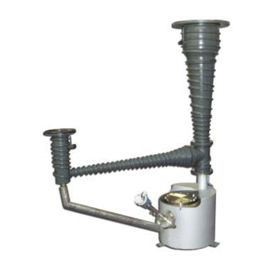
- Page 1 B065-10-880 Issue A Original Instruction Manual 18B4B Vapour Booster Pumps...
- Page 2 This page intentionally blank.
-
Page 3: Table Of Contents
18B4B Vapour Booster Pumps CONTENTS PAGE Section Page INTRODUCTION Scope and definitions Description Construction Principle of operation Over-temperature protection 1.5.1 Cooling-fail thermal snap-switches 1.5.2 Boiler-protection thermal snap-switch Low fluid level protection (optional) Temperature indication (optional) Operation with high ambient humidity... - Page 4 18B4B Vapour Booster Pumps CONTENTS (CONTINUED) PAGE Section Page 3.12 Filling procedure 3.12.1 Introduction 3.12.2 General filling procedure 3.12.3 Filling procedure for adjustment of the fluid low level switch 3.13 Connect the optional fluid low level switch (if fitted) OPERATION...
- Page 5 Service Spares Accessories RETURN OF BOC EDWARDS EQUIPMENT ILLUSTRATIONS Figure Page Part-sectional view of the 18B4B pump Typical performance curves Dimensions (mm) Heater wiring connections Terminal block Terminal block links for Star connections Star connection wiring diagram Terminal block links for Delta connections...
- Page 6 18B4B Vapour Booster Pumps PAGE SUPPLEMENTARY PUBLICATIONS Publication title Publication Number iTEMP PCP TMT 181 Temperature head transmitter KA 141R/09/a3/07.02 51004624 liquiphant S FTL70, FTL71 Level Limit Switch KA 172F/00/a6/04.03 52009621 liquiphant M FTL 51 High Pressure Sliding Sleeve KA 153F/00/a6/12.99 52004587 Note: The above manufacturer’s instructions will only be provided with pumps supplied...
-
Page 7: Introduction
This manual provides installation, operation and maintenance instructions for the BOC Edwards Description 18B4B Vapour Booster Pumps. You must use the pumps as specified in this manual. The 18B4B pumps are high performance vapour booster pumps, and have pumping speeds of up to... -
Page 8: Principle Of Operation
18B4B Vapour Booster Pumps The ejector nozzle (8) is housed in the ‘T’ piece (38), Principle of operation which is bolted to the side cone (14) into which the PAGE Refer to Figure 1. Pump fluid is heated in the boiler ejector discharges. -
Page 9: Boiler-Protection Thermal Snap-Switch
18B4B Vapour Booster Pumps 1.5.2 Boiler-protection thermal snap- Operation with high ambient switch humidity PAGE The pump has a boiler protection thermal snap- When the pump is switched off, the heaters in the switch (Figure 3, item 20) fitted to the wall of the pump will absorb moisture: this will cause a boiler. - Page 10 48. Setting dimension: 1.6 mm * * This is the setting dimension for AP201 fluid. This dimension may differ if you use a different fluid: refer to Section 5.6.6. Figure 1 - Part sectional view of the 18B4B pump: key Issue A Feb 04...
- Page 11 18B4B Vapour Booster Pumps PAGE Figure 1 - Part-sectional view of the 18B4B pump Feb 04 Issue A...
- Page 12 18B4B Vapour Booster Pumps PAGE This page intentionally blank. Issue A Feb 04...
-
Page 13: Technical Data
18B4B Vapour Booster Pumps TECHNICAL DATA PAGE Operating and storage conditions Maximum ambient operating temperature Typical surface temperature during operation Jet stage cone Boiler Maximum surface temperature during operation Jet stage cone Under covers/below the pump Minimum backing pump displacement... -
Page 14: Mechanical Data
BSP female (with inch NPT male adaptors) Table 3 - Mechanical data Pump fluid data Note: A BOC Edwards Material Safety Data Sheet for the fluid specified below is available on request. Recommended fluid type Apiezon AP201 Fluid charge Nominal 10 l... -
Page 15: Electrical Data
18B4B Vapour Booster Pumps Electrical data Heater rating 2 kW PAGE Nominal heater power (3 heaters) 6 kW Electrical supply Nominal 200 V supply 200 - 210 V, 50/60 Hz, three-phase Nominal 220 V supply 220 - 230 V, 50/60 Hz, three-phase... -
Page 16: Pump Item Numbers
B065-32-240 380 V B065-12-380 B065-22-380 B065-32-380 415 V B065-12-415 B065-22-415 B065-32-415 460 V B065-12-460 B065-22-460 B065-32-460 18B4B pump, with Pt100 and fluid low level switch 200 V B065-13-200 B065-23-200 B065-33-200 220 V B065-13-220 B065-23-220 B065-33-220 240 V B065-13-240 B065-23-240 B065-33-240... - Page 17 18B4B Vapour Booster Pumps PAGE 1. Pumping speed (l s ) against inlet pressure (mbar/Pa) for nitrogen 2. Throughput (mbar l s ) against inlet pressure (mbar/Pa) for nitrogen Figure 2 - Typical performance curves Feb 04 Issue A...
- Page 18 18B4B Vapour Booster Pumps PAGE 1. Inlet 2. Cooling-water inlet 3. Outlet 4. Cooling-water outlet 5. Cooling-fail thermal snap-switches 6. Clearance required to remove heaters 7. Fluid low level switch (optional) 8. Electrical box 9. Earth (ground) stud 10. Pt100 temperature probe (optional) 11.
- Page 19 18B4B Vapour Booster Pumps PAGE Figure 3 - Dimensions (mm) Feb 04 Issue A...
- Page 20 18B4B Vapour Booster Pumps PAGE This page intentionally blank. Issue A Feb 04...
-
Page 21: Installation
18B4B Vapour Booster Pumps INSTALLATION • Disconnect the other components of the vacuum system from the electrical supply so PAGE that they cannot be operated accidentally. Safety • Vent and purge the vacuum system with WARNING nitrogen for 15 minutes before you start installation work. -
Page 22: Locate The Pump
18B4B Vapour Booster Pumps Pipelines connected to the pump inlet and outlet Locate the pump must be self-supporting. Where this is not possible, PAGE WARNING ensure that the pipelines impose as small a load as possible on the inlet and outlet flanges. -
Page 23: Free-Standing Installation
We recommend that you use BOC Edwards flexible pipelines. (Continued on page 18) Feb 04 Issue A... -
Page 24: Connect The Pump Inlet
18B4B Vapour Booster Pumps • Before you connect the pump to your vacuum 3.4.3 Connect the pump outlet system: inspect the inlet and outlet flange PAGE sealing faces and ensure that they are free of WARNING scratches; if necessary, refinish the sealing Conduct the outlet pipeline to a faces;... -
Page 25: Pump Fluid Drain Connection (Optional)
18B4B Vapour Booster Pumps Use the formula below to calculate the minimum If required, you can remove one of the cooling required cooling-water flow for the pump: couplings (Figure 1, items 36 and 40) to divide the PAGE cooling-coils into two separate cooling circuits. -
Page 26: Connect The Electrical Supply
18B4B Vapour Booster Pumps Connect the electrical supply We recommend that you connect the electrical supply to the pump through an RCCB (residual current circuit breaker): the RCCB will operate to PAGE 3.7.1 Electrical safety disconnect the electrical supply if the insulation resistance of the heaters is too small. -
Page 27: Heater Wiring Connections
18B4B Vapour Booster Pumps PAGE Figure 4 - Heater wiring connections A Top edge Figure 5 - Terminal block Feb 04 Issue A... -
Page 28: Terminal Block Links For Star Connections
18B4B Vapour Booster Pumps PAGE Figure 6 - Terminal block links for Star connections Figure 7 - Star connection wiring diagram Figure 8 - Terminal block links for Delta connections Figure 9 - Delta connection wiring diagram Issue A Feb 04... -
Page 29: Recommended Control Circuit
18B4B Vapour Booster Pumps PAGE 1. Connection to heaters 7. Control electrical supply 2. Overcurrent trip 8. Off switch 3. Contactor 9. Contactor coil 4. Off load isolator 10. On switch 5. Fuses 11. Connection to thermal snap-switches 6. Electrical supply... -
Page 30: Connect The Thermal Snap-Switches
The thermal snap-switches automatically reset when temperature probe (if fitted) the temperature of the pump returns to normal. If you have ordered your 18B4B pump with the Incorporate an interlock so that the electrical supply optional Pt100 temperature probe, the pump will be... -
Page 31: Leak Test The System
• Keep fluid containers closed when not in use. We recommend that you use Apiezon AP201 fluid in the 18B4B pumps. Please consult BOC Edwards • Prevent spills and minimise operations that or your supplier if you want to use other fluids. -
Page 32: Filling Procedure
18B4B Vapour Booster Pumps 3.12 Filling procedure Check the level with the dipstick. Add more fluid or drain fluid from the pump (refer to PAGE 3.12.1 Introduction Section 5.5) as necessary. When the fluid level is correct (indicated when The general procedure to fill the pump with fluid is the fluid level is shown on the upper mark on given in Section 3.12.2. -
Page 33: Vapour Pump Fluid Thermal Breakdown
18B4B Vapour Booster Pumps PAGE Auto- Break- Edwards Thermal ignition down Vapour Possible product breakdown Type of danger temp. temp. pump fluid injury (other fluid products type) ≈ 500 Silicone DC702, Decomposed Negligible Negligible fluids DC704EU, hydrocarbons (methyl DC705 and silicon... -
Page 34: Filling Procedure For Adjustment Of The Fluid Low Level Switch
18B4B Vapour Booster Pumps 3.12.3 Filling procedure for adjustment of Slowly adjust (raise) the height of the level switch probe in the sleeve until there is no the fluid low level switch PAGE continuity across the probe outputs (that is, the... -
Page 35: Operation
18B4B pump. If you do, this may result in an explosion or fire. If in If you have an RCCB in your electrical supply circuit, doubt about the compatibility of... -
Page 36: Start-Up
18B4B pump, then leave the If you need to adjust the snap-switch to operate at a 18B4B pump to warm up for 40 to 60 minutes. different temperature, use the following procedure: Close the backing valve, then open the roughing valve. -
Page 37: Adjust The Boiler Protection Thermal Snap-Switch
18B4B Vapour Booster Pumps Turn the set screw anticlockwise again by a complete turn (270 ); one complete PAGE anticlockwise revolution of the screw (in the direction of the arrow, 4) is equivalent to an increase in the operating temperature of... -
Page 38: Re-Admission Of Air To Your Vacuum System
The following method of shut-down of the system Close the baffle valve and ensure that the ensures that the 18B4B pump is left evacuated and backing valve is open. so prevents the absorption of air by the pump fluid. - Page 39 18B4B Vapour Booster Pumps PAGE 1. Backing gauge head 7. 18B4B pump 2. Pump air-admittance valve 8. Moisture trap 3. Roughing valve 9. Backing valve 4. High-vacuum baffle-valve 10. Holding valve 5. High-vacuum gauge head 11. Holding pump 6. Work chamber 12.
- Page 40 18B4B Vapour Booster Pumps PAGE This page intentionally blank. Issue A Feb 04...
-
Page 41: Maintenance
• A suitably trained and supervised technician BOC Edwards. must maintain the 18B4B pump. • Do not touch or inhale the thermal • Ensure that the maintenance technician is breakdown products of the pump fluid if the familiar with the safety procedures which pump has been overheated. -
Page 42: Maintenance Plan
18B4B Vapour Booster Pumps Maintenance plan Check the pump fluid-level PAGE The plan shown in Table 11 (see below) lists the If the pump boiler operates at a higher than normal maintenance operations necessary to maintain the temperature, check the level of fluid in the pump pump in normal use. -
Page 43: Inspect The Pump Fluid (And Drain If Necessary)
18B4B Vapour Booster Pumps Inspect the pump fluid (and drain if Clean and inspect the pump necessary) PAGE 5.6.1 Introduction Notes: 1. If required, you can remove the cleaning port cover (refer to Section 5.6.5) and inspect the WARNING pump fluid without having to drain the pump. - Page 44 18B4B Vapour Booster Pumps Disconnect the cooling-water supply and return 11. Unscrew and remove the top jet cap (47), then pipelines from the cooling-water inlet and remove the top and second stage vapour tubes PAGE outlet (4, 15). (5 and 6).
-
Page 45: Clean The Main Pump Components
18B4B Vapour Booster Pumps 5.6.3 Clean the main pump components 5.6.5 Clean the boiler and fluid return pipes PAGE Use the following procedure to clean the top cone Refer to Figure 1 and use the following procedure: assembly (45), ‘T’ piece (38) and guard ring (2): Undo and remove the four screws which secure Refer to Figure 1. -
Page 46: Reassemble The Pump
• If you use the pump with another fluid, Lightly coat the threads of the ejector nozzle (8) contact your supplier or BOC Edwards for with anti-seize compound, then screw the advice. nozzle into the boiler tube. -
Page 47: Prepare The Pump For Operation
18B4B Vapour Booster Pumps Clean the radiation shield 5.6.7 Prepare the pump for operation PAGE Keep the radiation shield (Figure 1, item 22) which WARNING surrounds the pump boiler clean to maintain Use suitable lifting equipment to thermal efficiency. move the pump. If you do not, you... -
Page 48: Replace A Pump Heater
18B4B Vapour Booster Pumps Replace a pump heater 5.8.2 Identify and remove the defective heater PAGE Note: Heater spares packs (see Section 7.3) contain new heaters, crimps, terminals, wires and Refer to Figure 13. Place a suitable support ceramic insulation beads. -
Page 49: Terminal Block
18B4B Vapour Booster Pumps PAGE A Side view B Top view 1. Terminal box 8. Heater mounting stud 15. Nickel wire with ceramic beads 2. Busbar 9. Heater 16. Earth (ground) wire 3. Terminal nut 10. Heater clamp and spacer assembly 17. -
Page 50: Assemble And Fit The New Heater
18B4B Vapour Booster Pumps 5.8.3 Assemble and fit the new heater 5.8.4 Reassemble the pump PAGE Refer to Figure 13. Crimp the nickel wires (14) WARNING to the heater: use the uninsulated butt-splices Use suitable lifting equipment to supplied. move the pump. Refer to Section 2.3 Cut the nickel wires (14) to the required for the mass of the pump. -
Page 51: Check The Heater Clamp Plate And Retaining Nuts
18B4B Vapour Booster Pumps Check the heater clamp plate and 5.11 Fault finding retaining nuts PAGE A list of fault conditions and their possible causes is You must regularly check the heater clamp plate and provided in Table 12 (page 46) to assist you in basic retaining nuts, to ensure that the heaters make good fault-finding. - Page 52 18B4B Vapour Booster Pumps Fault symptom Possible causes PAGE • The electrical supply connections are disconnected. The pump will not start. • The electrical supply thermal overload has tripped. • The electrical supply connections have become The pump shuts down.
- Page 53 18B4B Vapour Booster Pumps Fault symptom Possible causes PAGE • The pump fluid-level is incorrect. Pressure is unstable. • The guard ring is incorrectly fitted/adjusted. • The cooling-water flow is restricted. • The pump interior assembly is assembled incorrectly. • The cooling-water temperature is too high.
- Page 54 18B4B Vapour Booster Pumps PAGE This page intentionally blank. Issue A Feb 04...
-
Page 55: Storage And Disposal
18B4B Vapour Booster Pumps STORAGE AND Disposal DISPOSAL PAGE Dispose of the pump, pump fluid and any components removed from the pump safely in Storage accordance with all local and national safety and environmental requirements. Use the procedure below to store the pump:... - Page 56 18B4B Vapour Booster Pumps PAGE This page intentionally blank. Issue A Feb 04...
-
Page 57: Service, Spares And Accessories
Boiler protection thermal snap-switch B064-01-113 Table 13 - 18B4B accessories * This adaptor flange is required to fit the P12R12A baffle and isolation valve to the 18B4B pump, and is only available for EHVI flanged pumps. Feb 04 Issue A... - Page 58 Backing flange ‘O’ ring (EHVI/ANSI) H021-06-208 2 inch backing union ‘O’ ring (EHVI) H021-06-159 Table 14 - 18B4B pump spares * Heater spares packs contain heaters, crimps, terminals, wires and ceramic insulation beads. § As marked on the heater. Issue A...
-
Page 59: Return Of Boc Edwards Equipment
7. If the equipment is large, strap the equipment and its accessories to a wooden pallet. If the equipment is too small to be strapped to a pallet, pack it in a suitable strong box. 8. Fax or post a copy of the Declaration (HS2) to BOC Edwards. The Declaration must arrive before the equipment. - Page 60 Read the Return of BOC Edwards Equipment - Procedure (HS1) before you complete this Declaration • Contact BOC Edwards to obtain a Return Authorisation Number and to obtain advice if you have any questions • Send this form to BOC Edwards before you return your equipment...
- Page 61 This page intentionally blank.
-
Page 62: Service
PLEASE CONTACT ANY OF THESE COMPANIES FOR DETAILS OF OTHER SALES AND SERVICE CENTRES IN YOUR AREA. BOC Edwards is part of BOC Limited. BOC Edwards and the stripe symbol are trade marks of The BOC Group. © BOC Edwards 2003 Produced by Technical Publicity Techpublicity@edwards.boc.com...
Need help?
Do you have a question about the 18B4B and is the answer not in the manual?
Questions and answers