
Subscribe to Our Youtube Channel
Related Manuals for BOC Edwards iL70


Summary of Contents for BOC Edwards iL70
- Page 1 A533-71-880 Issue A Instruction Manual iL Dry Pumping Systems Manor Royal, Crawley, West Sussex, RH10 2LW, UK Telephone: +44 (0) 1293 528844 Fax: +44 (0) 1293 533453 http://www.bocedwards.com...
- Page 2 Declaration of Conformity BOC Edwards, Manor Royal, Crawley, West Sussex RH10 2LW, UK declare under our sole responsibility that the product(s) iL Dry Pumping Systems: iL70 iL600 iL70 iL600 460 V, 60 Hz, 3-phase A533-71-908 A533-72-908 A533-74-908 A533-75-908 200/208 V, 50/60 Hz, 3-phase...
- Page 3 A533-71-880 Setup Password iL Dry Pumping Systems - Setup Password The setup password for this equipment is preset as follows: SETUP PASSWORD: You can remove this sheet from the instruction manual and retain it in a safe place to prevent unauthorised access to the setup menus in the iL system.
-
Page 4: Table Of Contents
CONTENTS Section Title Page INTRODUCTION Scope and definitions Overview 1.2.1 The iL system 1.2.2 Applications The LCDP dry pump The LCDP gas system (sensor-configured iL systems only) The LCMB mechanical booster pump (iL600 only) Temperature control system 1.6.1 LCDP pump temperature control system 1.6.2 LCMB pump temperature control system (iL600 only) Exhaust system... -
Page 5: Title
3-22 3.18 Connect the cooling-water pipelines 3-24 3.19 Commission the iL system 3-25 3.19.1 Switch on an iL70 system 3-25 3.19.2 Configure and switch on an iL600 system 3-26 PUMP DISPLAY MODULE MENUS AND DISPLAY FORMATS Introduction General operation The CANCEL button... - Page 6 Section Title Page Start-up Check the nitrogen pressure and adjust if necessary (sensor-configured iL systems only) Monitor the status of the iL system Warning and alarm indications Manual shut-down 5.8.1 Normal manual shut-down 5.8.2 Fast manual shut-down Automatic shut-down 5.10 Emergency stop 5.11 Restart the LCMB pump after automatic pump shut-down (iL600 only)
- Page 7 8.4.7 iL Central Monitoring System 8.4.8 iL600 Pressure Control Kit (sensor-configured iL systems only) 8.4.9 iL Communications Module 8.4.10 iL Alternative Nitrogen Connection Kit RETURN OF BOC EDWARDS EQUIPMENT Tables Table Title Page Safety sensors 1-18 Technical data Full load current ratings...
- Page 8 (mm) Services connections dimensions (mm) Centre of mass dimensions (mm) and mass distribution Typical pumping speeds for iL70: pumping speed against pressure Typical pumping speeds for iL600: pumping speed against pressure iL70 power curves: electrical power input against inlet pressure...
- Page 9 Illustrations (continued) Figure Title Page Retighten a Swagelok fitting Fit a Swagelok fitting Clean the exhaust check-valve Try to turn the LCDP pump 6-24 iL Dry Pumping Systems...
-
Page 10: Introduction
Scope and definitions This manual provides installation, operation and maintenance instructions for the BOC Edwards iL70 and iL600 Dry Pumping Systems (abbreviated to iL system in the remainder of this manual). You must use the iL systems as specified in this manual. -
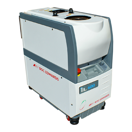
Page 11: Overview
The iL70 system has an LCDP70 dry pump; the iL600 system has an LCDP70 dry pump, with an LCMB600 mechanical booster pump fitted to the inlet of the LCDP pump. Throughout the remainder of this manual, the LCDP70 pump is referred to as the LCDP pump and the LCMB600 pump is referred to as the LCMB pump. - Page 12 Inlet LCMB oil filler-plug * LCMB pump-motor/gearbox * LCMB oil-level sight-glass * Gas Module LCDP pump-motor/gearbox LCDP oil filler-plug Levelling-foot Castor LCDP oil-level sight-glass LCDP pump Nitrogen pressure regulator Pump Display Module Emergency stop switch LCMB pump * Outlet Check-valve Exhaust-pipe * iL600 only Sensor-configured iL systems only...
-
Page 13: Applications
If you use the iL system on an application for which it is not suitable, you may invalidate your warranties. If in doubt, contact BOC Edwards who will advise you as to the suitability of the iL system for any particular application. -
Page 14: The Lcmb Mechanical Booster Pump (Il600 Only)
The purge flow pressure is controlled by the pressure regulator (7), and the purge flow to the shaft-seals (2) is switched on and off by the solenoid-valve (5). The pressure transducer (6) monitors the pressure of the shaft-seals purge flow. The output of the pressure transducer is used to display the shaft-seals purge pressure on the Pump Display Module (if fitted). -
Page 15: Lcmb Pump Temperature Control System (Il600 Only)
The pump-motor is cooled by water which flows through a cooling jacket which surrounds the motor. The cooling-water supply and return pipelines are connected to the iL system by connectors on the end of the iL system (see Figure 1-4). The cooling-water manifolds on the pump distribute the cooling-water to the pump cooling circuit and to the pump-motor cooling circuit (and to the LCMB pump-motor cooling circuit, on an iL600 system). -
Page 16: Exhaust System
A motor-protection thermistor is fitted to the pump-motor. This thermistor is identical to that fitted to the LCDP pump (see Section 1.6.1). The thermistor is connected to the internal control system and will temporarily switch off the LCMB pump and allow it to cool down if the pump-motor is too hot. - Page 17 Electrics and Pump Control Module Emergency stop switch Gas Module * Not used Sensor Monitoring Module * Gas Module and Sensor Monitoring Pump Display Module Module electrical supply * External electrical supply LCMB temperature sensor Electrical supply connector LCDP motor water manifold surface Protective earth (ground) stud temperature sensor GRC relay connector...
-
Page 18: Schematic Diagram Of The Electrical System
Figure 1-3 - Schematic diagram of the electrical system iL Dry Pumping Systems... - Page 19 Module (if fitted). Refer to detail E. Fuses inside the Module (16 to 21) protect the internal circuits of the Module. You cannot change these fuses; a BOC Edwards service engineer must change these fuses. 1-10 iL Dry Pumping Systems...
- Page 20 Rear panel D, E Detail of Electrics and Pump Control Module Blanking panel Protective earth (ground) stud Cooling-water outlet GRC relay connector # Cooling-water inlet d.c. electrical supply fuse holder (F7) Nitrogen inlet * Emergency stop fuse holder (F9)
-
Page 21: Services And Electrical Connections On The Rear Of The Il System
Figure 1-4 - Services and electrical connections on the rear of the iL system 1-12 iL Dry Pumping Systems... - Page 22 LCMB electrical supply cable (20) On an iL600 system, this is used to connect the electrical supply from the Electrics and Pump Control Module to the LCMB pump. iL70 Electrics Module detail iL600 Electrics Module detail LCMB pump 11. LCDP pump-body temperature sensor * LCMB pump-motor 12.
-
Page 23: Electrical Components (Shown Without Enclosure For Clarity)
Figure 1-5 - Electrical components (shown without enclosure for clarity) 1-14 iL Dry Pumping Systems... -
Page 24: Sensor Monitoring Module (Sensor-Configured Il Systems Only)
1.8.3 Sensor Monitoring Module (sensor-configured iL systems only) This Module communicates with the Gas Module, the Pump Display Module (if fitted) and the optional Interface Module accessories. The following sensors are connected to the Sensor Monitoring Module: • LCDP pump-body and pump-motor water manifold temperature sensors (if fitted) •... -
Page 25: Control Functions
1.10 Control functions 1.10.1 Priority of control The iL system can be controlled by a number of modules: the Pump Display Module (see Section 1.11); an iL Interface Module (see Section 8.4.5); or the iL Single Pumpset Monitor (see Section 8.4.7). Only one module can have control of the iL system at any one time. That is, once a module has control of the iL system, control requests from another Module are denied. -
Page 26: Setpoints, Warning And Alarm Conditions
1.10.2 Setpoints, warning and alarm conditions Note: Sensors which generate alarm and warning messages are not safety sensors: see Section 1.10.3. Each Module which monitors sensors has a microprocessor. Each monitored sensor has four associated setpoints. The setpoints are: the low warning setpoint, the high warning setpoint, the low alarm setpoint and the high alarm setpoint. -
Page 27: Pump Display Module (Optional Accessory)
Safety sensor Shut-down/switch off condition LCDP pump-motor thermistor When the thermistor in the LCDP pump- motor indicates that the temperature of the pump-motor is nominally 150 LCDP pump shut-down thermal When the thermal snap-switch operates to snap-switch indicate that the temperature of the LCDP pump-motor manifold is 60 C or higher. - Page 28 Use the menu (7), up (5), down (3), CANCEL (4) and ENTER (6) buttons as described below. Refer to Section 4 for a full definition of the menu structures and the display formats. Button LED colour Button use Normal Green Press this button to select the Normal display (see above).
-
Page 29: Accessories
1.12 Accessories A number of accessories are available to configure the iL system for your specific application. Refer to Section 8.4 for descriptions of these accessories. On button ENTER button Display Menu buttons Down button Menu selected LEDs CANCEL button Status LEDs Up button 10. -
Page 30: Technical Data
Maximum ambient operating humidity 90% RH Maximum exhaust back pressure 3 p.s.i. (0.207 bar, 2.07 x 10 Noise level measured at 1 m from the pump (with enclosure panels fitted) iL70 < 62 dB(A) iL600 < 62 dB(A) Mass iL70... -
Page 31: Technical Data
Parameter Units iL70 iL600 50 Hz m Typical peak pumping speed 60 Hz m mbar < 5 x 10 < 3 x 10 50 Hz < 5 < 3 x 10 Utimate vacuum mbar < 3 x 10 < 2 x 10 60 Hz <... -
Page 32: Il70 Dimensions (Mm)
Side view Plan view Inlet Outlet (as supplied) Air-extraction port Figure 2-1 - iL70 dimensions (mm) iL Dry Pumping Systems... -
Page 33: Il600 Dimensions (Mm)
Side view Inlet Plan view Outlet (as supplied) Air-extraction port Figure 2-2 - iL600 dimensions (mm) iL Dry Pumping Systems... -
Page 34: Services Connections Dimensions (Mm)
As supplied Cooling-water outlet (as supplied) Alternative positions Cooling-water inlet (as supplied) Nitrogen inlet: sensor-configured iL systems only (as supplied) Cooling-water outlet (alternative position) Cooling-water inlet (alternative position) Nitrogen inlet: sensor-configured iL systems only (alternative position) Figure 2-3 - Services connections dimensions (mm) iL Dry Pumping Systems... -
Page 35: Centre Of Mass Dimensions (Mm) And Mass Distribution
Levelling-foot Mass distribution on levelling-feet (kg) Levelling-foot Levelling-foot Levelling-foot iL70 54.2 51.7 55.3 Centre of mass iL600 122.2 87.9 95.2 Figure 2-4 - Centre of mass dimensions (mm) and mass distribution iL Dry Pumping Systems... -
Page 36: Typical Pumping Speeds For Il70: Pumping Speed Against Pressure
60 Hz Figure 2-5 - Typical pumping speeds for iL70: pumping speed against pressure 60 Hz Note: The discontinuity at inlet pressure of 20 mbar (2 x 10 Pa) indicates where the LCMB pump is 50 Hz automatically switched off: refer to Section 5.9. -
Page 37: Il70 Power Curves: Electrical Power Input Against Inlet Pressure
60 Hz 50 Hz Figure 2-7 - iL70 power curves: electrical power input against inlet pressure Note: The discontinuity at inlet pressure of 20 mbar 60 Hz (2 x 10 Pa) indicates where the LCMB pump is 50 Hz automatically switched off: refer to Section 5.9. -
Page 38: Temperature Control System
100 psig (6.9 bar, 6.9 x 10 Water supply temperature 10 to 30°C Typical pressure differential across supply and return * iL70 15 psi (1.03 bar, 1.03 x 10 iL600 15 psi (1.03 bar, 1.03 x 10 Minimum required flow rate for... -
Page 39: Lubrication
Lubrication Note: A BOC Edwards Material Safety Data Sheet for the oil referenced in the following sections is available on request. 2.5.1 LCDP pump Gearbox Oil charge 0.75 litres (typical) Grade of oil SAE 40 ISO viscosity grade Recommended perfluoropolyether oils Fomblin 25/6, Krytox 1525, Drynert 25/6 2.5.2... -
Page 40: Gas System (Sensor-Configured Il Systems Only)
50 Hz 60 Hz 60 Hz 50 Hz 60 Hz Full load (A) LCDP motor rating (kW) 1.85 1.85 iL70 Maximum power input to pump motor (kW) Full load both pump 14.2 15.3 14.4 motors(A) iL600 LCMB motor rating (kW) Maximum power input to 7.09... -
Page 41: Default Setpoints
Materials in the swept volume • • SG iron - 420/12 Grade 250 cast iron • • Viton PFA (perfluoroalkoxy) • Loctite 577 thread sealant Sealing materials • • Grade 250 cast iron Stainless steel 304 • • Viton Glass •... -
Page 42: Sensor Monitoring Module Default Setpoints (Sensor-Configured Il Systems Only)
Default setpoint values Parameter Unit High Low alarm High alarm warning warning LCDP power consumption LCMB power consumption * * Il600 only. # LCMB power threshold is 7.3 kW; maximum time in overload is 15 seconds. Table 2-3 - Electrics and Pump Control Module default setpoints Default setpoint values Parameter Unit... -
Page 43: Item Numbers
2.11 Item Numbers 2.11.1 Standard iL systems Electrical supply iL70 iL600 460 V, 60 Hz, 3-phase A533-71-908 A533-72-908 200/208 V, 50/60 Hz, 3-phase A533-71-945 A533-72-945 380/415 V, 50 Hz, 3-phase A533-71-946 A533-72-946 230 V, 60 Hz, 3-phase A533-71-957 A533-72-957 2.11.2... -
Page 44: Installation
Do not reuse 'O' rings and do not allow debris to get into the iL system during installation. • Consult BOC Edwards publication P300-20-000 (Vacuum Pump and Vacuum System Safety) before you pump hazardous materials. This publication is available on request: contact your supplier or BOC Edwards. - Page 45 Connect an additional RF earth (optional) 3.16.4 Refit the enclosure panels 3.17 Connect the cooling-water pipelines 3.18 Commission the iL system 3.19 Switch on an iL70 system 3.19.1 Configure and switch on an iL600 system 3.19.2 Table 3-1 - Installation checklist iL Dry Pumping Systems...
-
Page 46: Unpack And Inspect
Unpack and inspect WARNING You must use suitable lifting equipment to move the iL system. It is too heavy to lift by hand. WARNING Ensure that the maximum angle between paired slings used to lift the iL system is 60 The iL system is supplied sealed in a foil bag. -
Page 47: Checklist Of Components
Module connector terminator plug Emergency stop switch guard * Electrical supply connector * If required, fit this over the emergency stop switch to prevent inadvertent operation of the switch. iL70 only. Table 3-2 - Checklist of components iL system Bracket... -
Page 48: Lifting-Bolt Positions
Lifting-bolts iL600 Lifting-bolt holder Figure 3-2 - Lifting-bolt positions iL Dry Pumping Systems... -
Page 49: Remove The Enclosure Panels
Remove the enclosure panels 1. Refer to Figure 3-3. If you have an iL 600 system, continue at Step 2, otherwise continue at Step 4. 2. Refer to detail A. Remove the LCMB right-hand side panel from the iL system: •... -
Page 50: Remove/Refit The Enclosure Panels
Top panel Locating plates iL70 Catches (on rear of item 1) Screws (2 off) Catches Lower cover Right-hand side panel Figure 3-3 - Remove/refit the enclosure panels iL Dry Pumping Systems... - Page 51 7. Apply a suitable thread sealant (such as Loctite 577) to the threads of the male connector on the rear of the cooling-water outlet quick-release connector (6), then fit the female connector on the end of the water return hose (2) to the connector. 8.
-
Page 52: Reconfigure The Cooling-Water Connections (If Required)
As supplied Alternative configuration Water manifold Cooling-water inlet (quick-release connector) Water return hose Cooling-water outlet (quick-release connector) Water supply hose Front bulkhead Rear bulkhead Figure 3-4 - Reconfigure the cooling-water connections (if required) iL Dry Pumping Systems... -
Page 53: Locate The Il System
Locate the iL system WARNING You must use suitable lifting equipment to move the iL system. It is too heavy to lift by hand. WARNING Ensure that the maximum angle between paired slings used to lift the iL system is 60 Use the following procedure to locate the iL system in its operating position. -
Page 54: Check The Pump Oil-Levels
3.7.1 iL70 systems The iL70 system is supplied with the LCDP pump filled with oil. However, we recommend that you check the oil-level before you operate the iL system; use the method described below. Refer to Figure 1-1. Check the oil-level against the MAX mark (see detail B) on the bezel of the LCDP oil-level sight-glass (10): •... -
Page 55: Install Other Optional Accessories
2. Use the 'O' ring supplied (iL70 systems only) and the nuts, bolts and washers (removed in Step 1) to connect the inlet-flange of the iL system to your vacuum system. -
Page 56: Fit The Pump Display Module (Optional Accessory)
Remove the blanking panel Fit the Pump Display Module Recess Blanking panel Cable Front panel Pump Display Module Connector Viewing angle adjuster Connector Figure 3-6 - Fit the Pump Display Module (optional accessory) iL Dry Pumping Systems 3-13... -
Page 57: Connect The Il Exhaust Outlet To Your Exhaust-Extraction System
• Incorporate flexible pipelines in the exhaust pipeline to reduce the transmission of vibration and to prevent loading of coupling-joints. We recommend that you use BOC Edwards braided flexible pipelines. •... -
Page 58: Connect The Nitrogen Supply (Sensor-Configured Il Systems Only)
Note: If you need further information on leak testing, contact your supplier or BOC Edwards for advice. Leak-test the system after installation and seal any leaks found. Dangerous substances which leak from the system will be dangerous to people and there may be a danger of explosion if air leaks into the system. -
Page 59: Install Additional Safety Equipment (Optional)
3.14 Install additional safety equipment (optional) WARNING If your Process Tool/control system needs to know the total flow rate of nitrogen to the iL system for safety reasons, install suitable measurement equipment in the nitrogen supply pipeline. On a sensor-configured iL system, if you need to know the total flow rate of nitrogen to the LCDP pump for safety reasons, you should fit suitable measurement equipment in the nitrogen supply pipeline. -
Page 60: Leak-Test Port Position
Inlet spool piece LCMB pump iL600 Leak-test port (blanked) Leak-test port (blanked) LCDP pump Support manifold Figure 3-7 - Leak-test port position iL Dry Pumping Systems 3-17... -
Page 61: Electrical Supply And Rf Earth (Ground) Connections
3.16 Electrical supply and RF earth (ground) connections 3.16.1 Reconfigure the iL system for your electrical supply (if necessary) Your iL system will be supplied correctly configured for your electrical supply; the Item Number of the iL system (shown on the rating plate: Figure 3-9, item 1) specifies how the system is configured: refer to Section 2.11. -
Page 62: Reconfigure The Il System For Your Electrical Supply (If Necessary)
Electrics and Pump Control Module iL600 system Cover Screw Common cable Voltage select cable Terminal-block Figure 3-8 - Reconfigure the iL system for your electrical supply (if necessary) iL Dry Pumping Systems 3-19... -
Page 63: Connect The Electrical Supply To The Il System
7. If you have an iL600, continue at Step 8, otherwise continue at Section 3.16.3. 8. Refer to detail B. Undo and remove the four screws (7) which secure the Electrics and Pump Control Module (6) to the rear of the iL system, then carefully lower and support the Module. Ensure that you do not disconnect, break or damage any of the cables connected to the Module. -
Page 64: Reconfigure The Pump-Motor Terminal-Box (If Necessary)
High voltage configuration Low voltage configuration Rating plate (on Electrics and Pump Control Module) Pump-motor terminal-box cover Screws (4 off) Blanking plate Screws (6 off) Electrics and Pump Control Module Screws (4 off) Pump-motor terminal-box Links... -
Page 65: Connect An Additional Rf Earth (Optional)
(for example, use braided cable). 3.17 Refit the enclosure panels 1. Refer to Figure 3-3, detail A (iL600) or detail B (iL70). Refit the top panel: • Place the front of the top panel (1) on the top of the iL system. -
Page 66: Connect The Electrical Supply Cable To The Connector Mating-Half
Pin 1 (phase 1) Pin 2 (phase 2) Pin 3 (phase 3) Earth (ground) screw Strain relief bush Electrical supply cable Cover Connector block Electrical supply connector 10. Electrics and Pump Control Module Figure 3-10 - Connect the electrical supply cable to the connector mating-half... -
Page 67: Connect The Cooling-Water Pipelines
2. Refer to detail B. Refit the LCDP right-hand side panel: • Hold the panel (4) and fit it to the side of the iL system, so that the locating plates on the frame (5) engage in the slots in the bottom of the panel (4). •... -
Page 68: Commission The Il System
3.19.1 Switch on an iL70 system 1. Switch on the external electrical supply and check that the power on lamp (Figure 1-4, item 7) goes on. If the lamp does not go on, refer to Section 6 to determine the cause of the fault. -
Page 69: Configure And Switch On An Il600 System
You can only use the following procedure to configure an iL600 system if you have a Single Pumpset Monitor (SPM) connected to the iL system. If you do not have SPM, you cannot use the following procedure: contact your supplier or BOC Edwards for advice. CAUTION Do not operate an iL600 system with the maximum inlet pressure for longer than the maximum time specified in Table 2-1. - Page 70 5. Ensure that the exhaust-extraction system is not blocked (for example, that valves in the exhaust-extraction system are open). 6. Ensure that all openings to atmospheric pressure in the foreline vacuum system are closed, then switch on the iL system and simultaneously start the stop-watch. 7.
- Page 71 3-28 iL Dry Pumping Systems...
-
Page 72: Pump Display Module Menus And Display Formats
PUMP DISPLAY MODULE MENUS AND DISPLAY FORMATS Introduction The menus used and the display messages shown on the Pump Display Module are described in the menu diagrams in Figures 4-2 to 4-19. The following symbols and conventions are used in the menu diagrams: These are flow lines. -
Page 73: General Operation
General operation When you first switch on the iL system, the normal display is shown: see Figure 4-5. Refer to Figure 4-1. You can then press the On or Off button (1 or 10) or any of the four menu buttons (7) to enter the corresponding menu. -
Page 74: The Cancel Button
The CANCEL button You can press the CANCEL button at any time during menu operation. For this reason, we have not shown the use of the CANCEL button on all of the menu diagrams, but we have shown specific uses where there is no other obvious way to cancel the current menu option and enter the previous menu option. -
Page 75: Wrap-Around
Wrap-around When you use the up and down buttons to change a digit or character on the display, the digit or character will 'wrap-around' between its minimum and maximum values. For example, when you enter a password digit, if the digit is '0' and you press the down button, the digit will change to '9';... -
Page 76: Menu Structure
8. Press the ENTER button; the display will then show 'Pressure' on the top line and the currently selected pressure units on the bottom line. 9. Press the up or down buttons to change the units displayed to the required units, then press the ENTER button. -
Page 77: Switch On
From any menu <Any display on the Pump Display Module> Normal Normal [4-5] Status Status [4-6] Control Control [4-7] Setup Setup [4-8] Switch on [4-3] If the Pump Display Module does not have control when you try to switch on or switch off the Switch off [4-4] pumping system, an... -
Page 78: Normal
Switch on Single pump ENTER Pump off menu (that is, CANCEL Clears no load-lock pump is ENTER connected). SELECT PUMP ENTER Process pump SELECT PUMP ENTER Only available if you Load lock pump have an iL Interface Module fitted with an Auxiliary Interface Card connected to the iL system. -
Page 79: Switch Off Menu
Switch off Single pump ENTER Pump off menu (that is, CANCEL Clears no load-lock pump is connected). ENTER SELECT PUMP ENTER Process pump Multi pump menu (that is, a load-lock pump is connected). SELECT PUMP Only available if you have ENTER Load lock pump an iL Interface Module... -
Page 80: Normal Menu
Normal ∆∆.∆ kW DP POWER First page of the normal display ∆∆.∆ C DP BODY On a standard iL system, <NP> will be shown instead of a temperature value. ∆∆.∆ kW MB POWER Second page of the normal display. ∆∆.∆ C MB TEMP On a standard iL system, <NP>... -
Page 81: Status
Status Last parameter [4-6/2] ∆∆.∆ A ∆∆.∆ kW DP POWER ∆∆.∆ A ∆∆.∆ kW MB POWER ∆∆∆ H RUN HOURS ∆∆∆ H PROCESS ∆∆∆ PROCESS ∆∆∆ CYCLES ∆∆∆.∆ C MB TEMP On a standard iL system, ∆∆∆.∆ C DP MOTOR <NP>... - Page 82 Prev parameter Next parameter [4-6/1] [4-6/1] DP OIL <NP> MB OIL <NP> H2O FLOW <status> TOTAL N2 <NP> EXHAUST <NP> ∆∆.∆ PSI SS PURGE FINAL <NP> <NP> ∆∆∆s PUMP STOP ∆∆∆s ZERO TIME Last parameter [4-6/1] If you have fitted an active gauge <NP>...
-
Page 83: Control
Control Release control < ENTER Normal [4-5] Take control Release control ENTER Normal [4-5] Take control < Figure 4-7 - Control menu 4-12 iL Dry Pumping Systems... -
Page 84: Setup
Select option entered, access to the service [4-8/2] menu becomes available: the service password is only available to BOC Edwards service engineers. Normal [4-5] If the password was incorrect, revert to normal display Figure 4-8 - Setup menu: sheet 1 of 3... -
Page 85: Inlet Purge
Select option Last option [4-8/3] [4-16/3] SETUP MENU ENTER Inlet purge Turn on/off [4-16/3] SETUP MENU ENTER Gas Ballast Turn on/off [4-16/2] SETUP MENU ENTER Valve 1 Open/close [4-16/2] SETUP MENU ENTER Valve 2 Open/close [4-9] SETUP MENU ENTER Run til crash Run til crash Prev option Next option... - Page 86 Next option Prev option [4-8/2] [4-10] SETUP MENU ENTER Units Units [4-11] SETUP MENU ENTER Normal Display Normal Display SETUP MENU Service [4-12/1] ENTER Service [4-18] SETUP MENU ENTER Messages Messages Last option Select option [4-8/2] [4-8/2] Figure 4-8 - Setup menu: sheet 3 of 3 iL Dry Pumping Systems 4-15...
-
Page 87: Run Til Crash
Run til crash RUN TIL CRASH ENTER RUN TIL CRASH ENTER Exit Return to [4-8/2] Figure 4-9 - Run til crash menu 4-16 iL Dry Pumping Systems... -
Page 88: Units
Units Press the CANCEL button at any time to exit this menu and return to [4-8/3]. UNITS SELECT Pressure Units ENTER ENTER Pressure <units> Use the up and down buttons to select the new units:PSI or kPa UNITS SELECT Temperature Unit ENTER ENTER Temperature... -
Page 89: Normal Display
Normal Display SELECT LINE ENTER Change the first line of Top page 1 page 1 of the Normal Display SELECT LINE Change the second line of ENTER Bottom page 1 page 1 of the Normal Display SELECT LINE Change the first line of ENTER Top page 2 page 2 of the Normal Display... -
Page 90: Service
Service Select option If you entered the service [4-12/2] password when prompted for the setup password in SERVICE PASSWORD the Setup menu, you can ∆∆∆ Password directly access the select option menu. Use the up and down buttons to increase or decrease the first digit of the password. -
Page 91: Serial Numbers
Select option [4-13] SERVICE MENU ENTER Serial Menu Serial Numbers [4-14] SERVICE MENU ENTER Zero sensors Zero Sensors [4-16/1] SERVICE MENU ENTER Manual Manual SERVICE MENU View Status ENTER View status [4-17] [4-15] SERVICE MENU ENTER Gas Valve Control Gas Valve Contrl Figure 4-12 - Service menu: sheet 2 of 2 4-20 iL Dry Pumping Systems... -
Page 92: Serial Menu
Use this menu to display serial Serial Menu numbers or the user tag. Note that you cannot change these items. Press the CANCEL button at any time to exit the menu and return to [4-12/2] SERIAL MENU DP SYSTEM S/N ENTER DP System S/N <serial no./tag>... -
Page 93: Zero Sensors
Note: This menu is not used in the iL system: you can select the menu and press buttons as shown below, but menu actions will have no effect on iL system operation. Zero sensors ZERO SENSORS Press ENTER ENTER Exit (or CANCEL) to exit menu and return to... -
Page 94: Gas Valve Contrl
Note: This menu is not used in the iL system: you can select the menu and press buttons as shown below, but menu actions will have no effect on iL system operation. Gas Valve Control Calibrating Shaft Seals ENTER ∆∆∆ SLM N2 Flow 2/3 Interstage ENTER... -
Page 95: Manual
Manual Last option [4-16/2] [4-16/3] MANUAL MENU ENTER Turn on/off DP Only See notes in Section 5.13 [4-16/3] MANUAL MENU ENTER Turn on/off See notes in Section 5.13 [4-16/3] MANUAL MENU ENTER Turn on/off Load lock pump [4-16/3] MANUAL MENU ENTER Turn on/off Nitrogen Supply... - Page 96 Next option Prev option [4-16/1] [4-16/2] MANUAL MENU ENTER Open/close Valve 1 [4-16/2] MANUAL MENU ENTER Open/close Valve 2 Last option Manual [4-16/1] [4-16/1] Open/close VALVE ∆ ENTER Open VALVE ∆ ENTER Close Return to Exit above or to [4-8/1] Figure 4-16 - Manual menu: sheet 2 of 3 iL Dry Pumping Systems 4-25...
- Page 97 Turn on/off <parameter> <parameter> is the prev- ENTER iously selected device: DP, MB, Load Lock Pump, Nitrogen supply, Gas Ballast or Inlet Purge. <parameter> ENTER Exit Return to [4-8/2] or [4-16/1] Figure 4-16 - Manual menu: sheet 3 of 3 4-26 iL Dry Pumping Systems...
-
Page 98: View Status
View Status Last parameter [4-17/2] ∆∆.∆ A ∆∆.∆ kW DP POWER ∆∆.∆ A ∆∆.∆ kW MB POWER ∆∆∆ H RUN HOURS ∆∆∆ H PROCESS ∆∆∆ PROCESS ∆∆∆ CYCLES ∆∆∆.∆ C On a standard iL system, MB TEMP ∆∆∆.∆ C <NP> will be shown instead DP MOTOR of temperature values. - Page 99 Next parameter Prev parameter [4-17/1] [4-17/1] DP OIL <NP> MB OIL <NP> H2O FLOW <status> TOTAL N2 <NP> EXHAUST <NP> ∆∆.∆ PSI SS PURGE FINAL <NP> <NP> ∆∆∆s PUMP STOP ∆∆∆s ZERO TIME Last parameter [4-17/1] <NP> If you have fitted an active gauge GAS TYPE accessory, a pressure will be displayed instead of <NP>.
-
Page 100: Messages
Messages MESSAGES ENTER English MESSAGES ENTER Downloaded Exit Return to [4-8/3] Figure 4-18 - Messages menu iL Dry Pumping Systems 4-29... -
Page 101: Warning And Alarm Messages Menu
Wng & Alarm Messages ALARM <e.no> WARNING <e.no> <message> <message> ENTER <message> Display advisory message (if any) <message> ENTER Normal [4-5] Figure 4-19 - Warning and alarm messages menu 4-30 iL Dry Pumping Systems... -
Page 102: Operation
If you press the up or down button, the Pump Display Module will then show the second page of normal display; as supplied, the information shown on the second page is: • ("<NP>" shown for iL70 systems: see Section 4.4) LCMB pump power consumption •... -
Page 103: Change The Display Units
5.2.2 Change the display units If required, you can change the Pump Display Module display units: • Pressures shown on the Pump Display Module can be displayed in either kPa or psi. Use the Setup/Units/Pressure menu to change the pressure display units. •... -
Page 104: Start-Up
Start-up WARNING Do not operate the iL system with any enclosure panels removed and do not touch any parts of the pump(s) when the iL system is on. Surfaces of the pump(s) are very hot and can cause injury to people. WARNING Ensure that it is safe to start the iL system. -
Page 105: Check The Nitrogen Pressure And Adjust If Necessary (Sensor-Configured Il Systems Only)
Check the nitrogen pressure and adjust if necessary (sensor-configured iL systems only) Note: You must only check and adjust the nitrogen pressure after the iL system has been operating for at least four hours, so that the LCDP pump is at its correct operating temperature. You must check and adjust the nitrogen pressure when you first use the iL system. -
Page 106: Status Menu Display Options
Sensor data Units Notes LCDP pump current consumption LCDP pump power consumption LCMB pump current consumption * LCMB pump power consumption * Total running time hours Total run-time of the iL system. Process running time hours Total run-time on process. Process cycles Process cycles. -
Page 107: Warning And Alarm Indications
Warning and alarm indications Notes: Refer to Section 6 for a full list of the warning and alarm messages and their meanings. If a warning or alarm condition exists: • The top line of the display on the Pump Display Module will change to 'WARNING' or 'ALARM', together with an error number. -
Page 108: Fast Manual Shut-Down
When you select this shut-down option, the following actions will occur (with a small time delay between each action): • On an iL600 system, the LCMB pump is switched off. • The LED on the On button on the Pump Display Module (Figure 1-7, item 1) starts to flash. •... -
Page 109: Emergency Stop
• The LED on the On button on the Pump Display Module goes off. If required, you can request 'run til crash' operation. In this mode of operation, most alarm conditions will be ignored and the iL system will continue to operate. Note however that for safety reasons the following alarms will shut down the iL system even if you have selected 'run til crash': •... -
Page 110: Restart The Il System After Emergency Stop Or Automatic Shut-Down
5.12 Restart the iL system after emergency stop or automatic shut-down Note: If the iL system has automatically shut down because of high LCDP pump power (alarms 412 and 512), check that the LCDP pump is free to rotate before you restart the iL system: refer to Section 6.15. -
Page 111: Operation Of The Load-Lock Pump
In normal operating conditions, the components of the iL system are operated automatically. If necessary (for example, for fault finding purposes), you can control the operation of iL system components separately: • Use the Setup/Service/Manual/Valve menu to control the operation of the gate valves (that is open or close the valves). -
Page 112: Maintenance
The iL system may have overheated if it was misused, if it malfunctioned or if it was in a fire. BOC Edwards Material Safety Data Sheets for fluorinated materials used in the iL system are available on request: contact your supplier or BOC Edwards. -
Page 113: Recommended Purge Method
6.1.2 Recommended purge method Note: To use the following procedure to purge the iL system, you must be able to introduce nitrogen purge gas into the foreline without disconnecting any of the vacuum connections. We recommend that you purge the iL system as described below before you do maintenance. You must use this purge procedure if you have pumped dangerous substances, or if you think that fluorinated materials in the pump may have overheated and undergone thermal breakdown. -
Page 114: Fit A Swagelok Fitting
Swagelok connector Front (tapered) ferrule Tube Rear ferrule Figure 6-1 - Fit a Swagelok fitting Swagelok connector Front (tapered) ferrule Rear ferrule Tube Figure 6-2 - Retighten a iL Dry Pumping Systems... -
Page 115: Reconnect Swagelok Connector
The frequency of maintenance operations depends on your process. Adjust the frequency of maintenance operations according to your experience. When you maintain the iL system, use BOC Edwards maintenance and service kits. These contain all of the necessary seals and other components necessary to complete maintenance operations successfully. -
Page 116: Inspect And Clean The Exhaust-Pipe And Check-Valve
4. Check that all electrical connections are secure; tighten any loose connections. Inspect all electrical cables and connectors for damage; replace any cables and connectors that are damaged. 5. Check that all process and exhaust connections are secure; tighten any loose connections. Inspect all process and exhaust pipelines and fittings and check that they are not corroded or damaged;... -
Page 117: Clean And Refit The Check-Valve (If Fitted)
11. Use the bolt (removed in Step 4) to secure the bracket on the exhaust pipe (18) to the iL system. 12. Continue at Section 6.5.2 to clean and refit the check-valve (17). 6.5.2 Clean and refit the check-valve (if fitted) 1. -
Page 118: Clean The Exhaust Check-Valve
Spider leg Inlet-flange Valve body (female) 'O' ring Fluoroelastomer ball Flow direction arrow Valve body (male) Outlet-flange Figure 6-3 - Clean the exhaust check-valve iL Dry Pumping Systems... -
Page 119: Check The Lcmb Pump Oil-Level (Il600 Only)
If there is a significant loss of oil from the pump, the shaft-seals or the spinning filters may have failed. You cannot replace these items. Contact your supplier or BOC Edwards for advice. You must check the oil-level every three months; use the following procedure: 1. -
Page 120: Check The Lcdp Pump Oil-Level
Check the LCDP pump oil-level WARNING If you have pumped dangerous substances, ensure that you purge the iL system (refer to Section 6.1.2) before you remove the oil filler-plug. WARNING Do not remove the oil filler-plug while the pump is operating. If you do, hot oil may be ejected from the pump. -
Page 121: Change The Lcdp Pump Oil
Change the LCDP pump oil WARNING If you have pumped dangerous substances, ensure that you purge the iL system (refer to Section 6.1.2) before you remove the oil filler-plug. WARNING Do not remove the oil filler-plug while the pump is operating. If you do, hot oil may be ejected from the pump. -
Page 122: Change The Lcmb Pump Oil (Il600 Only)
Change the LCMB pump oil (iL600 only) WARNING If you have pumped dangerous substances, ensure that you purge the iL system (refer to Section 6.1.2) before you remove the oil filler-plug. WARNING Do not remove the oil filler-plug while the pump is operating. If you do, hot oil may be ejected from the pump. -
Page 123: Replace A Fuse
Note: You can only change the fuses in fuse holders F7, F8 and F9. A BOC Edwards service engineer must change other fuses in the Electrics and Pump Control Module (see Figure 1-4). You can only change the low voltage fuses F7 to F9 for the d.c. electrical supply, the iL Interface Module and the emergency stop circuit. -
Page 124: Relocate The Il System For Maintenance
6.13 Relocate the iL system for maintenance WARNING Use suitable lifting equipment to move the iL system. If you want to remove the iL system from its operating location and move it to another location where you will do maintenance, use the following procedure. Purge the iL system (refer to Section 6.1.2), then shut down the iL system as described in Section 5.8 and allow the iL system to cool down. -
Page 125: Fault Finding
6.14 Fault finding 6.14.1 Warning and alarm message fault finding When a warning or alarm message is generated, you can display the message and (for some of the messages) two lines of text (the advisory message) which identify possible checks you can make to identify the cause of the fault and to rectify the fault. -
Page 126: Warning Messages
Warning message Advisory message Meaning/recommended action WARNING (a) there is a fault in the Sensor Monitoring Module PCA, or (b) a module or sensor which should be fitted is not fitted or is disconnected, or (c) the emergency stop button has been pressed (or a safety sensor has operated or your external emergency stop switch has been operated) to shut down the iL system, or (d) - Page 127 Warning message Advisory message Meaning/recommended action WARNING SEE MANUAL The LCDP motor thermistor is short circuited. Check the thermistor connections inside the LCDP pump motor terminal-box and check the connections between the LCDP pump and the Electrics and Pump Control Module. There is a phase imbalance in the electrical WARNING SEE MANUAL...
- Page 128 Warning message Advisory message Meaning/recommended action WARNING 1011 SEE MANUAL There is a phase imbalance in the electrical supply to the LCMB pump. Check the electrical supply and the connections to the iL system. If the electrical supply and connections are correct, the pump motor may be faulty.
- Page 129 Warning message Advisory message Meaning/recommended action WARNING 5101 The Sensor Monitoring Module may be disconnected. If the wiring connections are correct, the PCA may be faulty. WARNING 5113 There is a fault in the ADC (analogue-to- digital convertor) in the Sensor Monitoring Module;...
- Page 130 Warning message Advisory message Meaning/recommended action WARNING 11101 There is a fault in the NIM (Network Interface Module): refer to the instruction manual supplied with the NIM. WARNING 12101 There is a fault in the Tool Interface Card in the iL Interface Module.
-
Page 131: Alarm Messages
(for example, cooling-water supply failure and thermocouple circuit failure) or the thermistor circuit has failed: contact your supplier or BOC Edwards. ALARM Refer to the recommended actions for error number 611: see Table 6-1. - Page 132 Alarm message Advisory message Meaning/recommended action ALARM 1012 Refer to the recommended actions for error number 1011: see Table 6-1. (a) the electrical supply is not connected to the ALARM 1101 LCDP pump-motor, or (b) the LCDP pump has started, but has then immediately stopped again, because the phase sequence of the electrical supply to the pump is incorrect: reverse two of the phases in the electrical...
-
Page 133: Fault Messages
Message Meaning CONTROL failed You have requested that the Pump Display Module takes control of the iL system, but the attempt to take control has Press CANCEL failed. Press the CANCEL button to return to normal display. CONTROL REMOTE (a) You have requested that the Pump Display Module takes control of the iL system, but another module still Press CANCEL has control. -
Page 134: Fault Parameters
Parameter Source/cause of error iL system status Electrical supply voltage LCDP pump current consumption LCDP pump power consumption LCDP pump-motor thermistor Phase imbalance in LCDP pump current consumption LCMB pump current consumption LCMB pump power consumption LCMB pump-motor thermistor Phase imbalance in LCMB pump current consumption LCDP pump status LCMB pump status Total run hours (since last service) -
Page 135: Fault Types
Fault type Meaning Digital alarm condition * Low warning condition Low alarm condition High warning condition High alarm condition Device error Last two digits of the error number. * For example, a pressure transducer has drifted outside the valid range. For example, sensor is not fitted, or is disconnected. -
Page 136: Check For Free Rotation Of The Lcdp Pump
6.15 Check for free rotation of the LCPD pump If the iL has automatically shut down because of excessive LCDP pump-motor power (that is alarms 412 or 512 are displayed), use the following procedure to check that the pump is free to rotate before you restart the iL system: 1. -
Page 137: Try To Turn The Lcdp Pump
Rear cover iL600 Plug and 'O' ring: 3/8 BSP Correct direction of rotation arrow Figure 6-4 - Try to turn the LCDP pump 6-26 iL Dry Pumping Systems... -
Page 138: Storage, Disposal And Transportation
STORAGE, DISPOSAL AND TRANSPORTATION Storage WARNING Do not drain the oil from the pump(s) if you know that dangerous substances have been pumped, or if you are unsure whether dangerous substances have been pumped or not. CAUTION Drain the cooling-water from the iL system, if you want to store it in conditions where the cooling-water could freeze. -
Page 139: Transportation
You must provide a correctly completed Return of Equipment Declaration (form HS2) if you return the iL system to BOC Edwards: refer to Section 8.2. If you want to transport the iL system (either for onward shipment to your own customer, or for return to BOC Edwards for repair), before you transport it: If applicable, ensure that the iL system has been purged (see Section 6.1.2) and shut down... -
Page 140: Service, Spares And Accessories
Note: Whenever you return the iL system to a BOC Edwards Service Centre or other BOC Edwards company, you must comply with the requirements of Section 7.3 and with the requirements of the Return of BOC Edwards Equipment Procedure (see forms HS1 and HS2 at the end of this manual). -
Page 141: Ordering Accessories
Spares Spare Item Number Fomblin 25/6 oil (1 kg) H113-12-019 Krytox 1525 oil (1 kg) H113-09-018 Drynert 25/6 oil (1 kg) H113-12-021 Exhaust check-valve servicing kit A440-03-820 iL Tool Interface Module connector plug A532-20-050 Exhaust pipe (as supplied) A408-02-038 Metal 'O' ring (for LCDP outlet/exhaust pipe connection) H021-15-000 Oil filler-plug 'O' ring (pack of 10) H021-06-110... -
Page 142: Active Gauge Connection Kit (Sensor-Configured Il Systems Only)
Connection Kit, and that you cannot fit an Active Gauge Connection Kit if you have fitted an iL Pressure Control Kit: see Section 8.4.8. The Connection Kit is suitable for use with any of the following BOC Edwards Active Gauges: ATC-M Active Thermocouple Gauge; ASG (1000 mbar) Active Strain Gauge; APG-MP Active Pirani Gauge. -
Page 143: Il Central Monitoring System
8.4.7 iL Central Monitoring System The iL Central Monitoring System allows you to network together all of the iL systems in your installation, and to use a PC to centrally monitor the iL systems. Contact your supplier or BOC Edwards if you want to network your iL systems. 8.4.8 iL600 Pressure Control Kit (sensor configured iL systems) Fit an iL600 Pressure Control Kit to an iL600 system to enable the LCMB pump to be... -
Page 144: Return Of Boc Edwards Equipment
Return of BOC Edwards Equipment - Procedure (Form HS1) Introduction Before you return your equipment you must warn your supplier if the substances you used (and produced) in the equipment can be dangerous. You must do this to comply with health and safety at work laws. - Page 145 Date of equipment delivery: ________________________________ I have made reasonable enquiry and I have supplied accurate information in this Declaration. I have not withheld any information. I have followed the Return of BOC Edwards Equipment Procedure (HS1) on the previous page. Signed: ___________________________________________________...
- Page 146 West Sussex, RH10 2LW 301 Ballardvale Street UNITED KINGDOM WILMINGTON, MA 01887 BOC Edwards is a trading name used by affiliate companies of The BOC Group plc. BOC Edwards and the stripe symbol are trademarks of The BOC Group plc.
Need help?
Do you have a question about the iL70 and is the answer not in the manual?
Questions and answers