Table of Contents
Advertisement
Quick Links
Advertisement
Table of Contents
Troubleshooting

Related Manuals for BOC Edwards Seiko Seiki STP603 Series


Summary of Contents for BOC Edwards Seiko Seiki STP603 Series
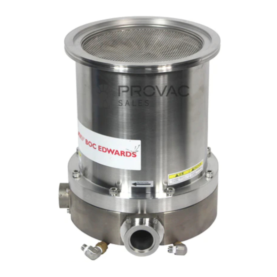
- Page 1 B721-00-880 Issue D Instruction Manual Seiko Seiki STP603/1003 (P039) Turbomolecular Pump System (Document number MT-39E-001-D) View our inventory Manor Royal, Crawley, West Sussex, RH10 2LW, UK Telephone: +44(0)1293 528844 Fax: +44(0)1293 533453 http://www.bocedwards.com...
- Page 2 Manual carefully before using the STP pump. Keep this Manual in a place where you can quickly access it at any time. BOC Edwards Japan Limited Dec. 2003 Copyright 2003 BOC Edwards Japan Limited. All rights reserved. Printed in Japan.
- Page 3 Safety Precautions as well as the general safety rules (your country’s laws, regulations, safety standards and so on). If the equipment is used in a manner not specified by BOC Edwards, the protection provided by the equipment may be impaired.
- Page 4 STP-603/1003 Series Instruction Manual The STP pump is provided with a high-speed rotor. Secure the STP ◇ pump according to the specified method. Failure to do so may lead to serious personal injury, product and/or peripheral equipment damage if any abnormality/error occurs in the rotor. The STP pump operates at high temperatures while the baking heater ◇...
- Page 5 STP-603/1003 Series Instruction Manual NEVER use any gas that is not specified as usable in this Manual. ◇ The use of such gas may corrode the STP pump and damage it. A hazardous live voltage may exist at connector/terminal that marked ◇...
- Page 6 (the STP pump serial number, the STP control unit serial number, and the STP connection cable length) is changed. Use the STP connection cable that BOC Edwards has specified. ◇ The use of different cables may result in product damage.
- Page 7 STP-603/1003 Series Instruction Manual NEVER turn OFF the primary power (DO NOT switch the breaker ◇ "OFF") while the STP pump is rotating. Doing so may result in product damage. Perform investigations into probable causes and remove them before ◇ restarting the STP pump in the event of the occurrence of a problem.
- Page 8 STP-603/1003 Series Instruction Manual INTRODUCTION Thank you very much for purchasing BOC Edwards’ turbomolecular pump. The turbomolecular pump is designed to be installed in the vacuum equipment to exhaust gases from it. This manual covers all items necessary to ensure safe installation, operation and...
- Page 9 1) No part of this manual may be reproduced in any form by any means without prior written permission from BOC Edwards. 2) BOC Edwards pursues a policy of continuing improvement in design and performance of this product. The right is, therefore, reserved to vary specifications and design without notice.
-
Page 10: Limited Warranty
1) This warranty applies only to the product delivered from BOC Edwards to the customer. 2) If any defect is found during this period, BOC Edwards will, at its option, repair or recondition the product free of charge. The costs for repair or replacement of the product after the warranty period has passed will be at your own charge. - Page 11 STP-603/1003 Series Instruction Manual 12) Product breakage or damage due to natural disasters, fire or other external factors; 13) Deterioration in the basic performance due to the use of the product beyond limits of the use; 14) Any direct, incidental or consequential damage resulting from the use of the product;...
-
Page 12: Table Of Contents
STP-603/1003 Series Instruction Manual TABLE OF CONTENTS SAFETY PRECAUTION INTRODUCTION PRECAUTIONS REQUEST LIMITED WARRANTY 1 Precautions for Safe Operation of the STP Pump..........1-1 Usable Gases........................1-1 Maintenance and Inspection Precautions................1-1 Labels..........................1-2 2 Operation Principle of the STP Pump..............2-1 3 Unpacking ...................... - Page 13 STP-603/1003 Series Instruction Manual 6.5.1 Connecting to Power.................... 6-12 6.5.2 Emergency Off Circuit (EMO Circuit) ..............6-12 7 How to Start/Stop the STP Pump............... 7-1 Before Starting ........................7-1 Start Procedures ......................... 7-2 Stop Procedures ......................... 7-2 Manual Operation........................ 7-3 7.4.1 Powering ON......................
- Page 14 STP-603/1003 Series Instruction Manual 12.1 Storage of the STP Pump ....................12-1 12.2 Storage of the STP Control Unit ..................12-1 12.3 Disposal ..........................12-2 13 Specifications ....................13-1 13.1 Specifications for the STP Pump ..................13-1 13.2 Specifications for the STP Control Unit................13-5 UNIT CONVERSION TABLE ANNEX MALFUNCTION INFORMATION...
- Page 15 STP-603/1003 Series Instruction Manual TABLES Table 3.1 Accessories ........................3-2 Table 4.1 Tightening torque of bolt ....................4-9 Table 4.2 Maximum Torque predicted and Recommended securing bolt for inlet port flange..4-10 Table 4.3 Number of Claw Clamps by Size of Flange..............4-11 Table 6.1 Connecting the Power Cable..................
- Page 16 STP-603/1003 Series Instruction Manual FIGURES Figure 2.1 Cross Sectional View of the STP Pump ............... 2-2 Figure 3.1 Example of Lifting the STP Pump ................. 3-2 Figure 4.1 Configuration of the STP Pump ..................4-2 Figure 4.2 Installation of the STP Pump to the Vacuum Equipment ..........4-6 Figure 4.3 STP Pump Installation Positions ..................
-
Page 17: Precautions For Safe Operation Of The Stp Pump
STP-603/1003 Series Instruction Manual Precautions for Safe Operation of the STP Pump Usable Gases Chlorine or fluorine system gases can be used in chemical specific pumps (STP-603C/1003C or other models). When you use gases including alkaline metals, but excluding Li, gases including Ga, Hg, In, or Sn, or HBr, contact BOC Edwards. -
Page 18: Labels
STP-603/1003 Series Instruction Manual Labels The following labels are affixed to the STP pump and STP control unit. Read the contents of the labels before operation. 1) STP Pump Caution Label This label describes precautions for operating the STP pump. Follow these precautions. - Page 19 STP-603/1003 Series Instruction Manual 4) STP Pump Installation Warning Label This label describes installation of the STP pump. Install the STP pump according to the precautions of Section 4, "Installation of the STP Pump." 5) STP Control Unit Safety Instruction Label This label describes instructions before operating the STP control unit.
- Page 20 STP-603/1003 Series Instruction Manual 7) High Voltage Device Caution Label The STP control unit is equipped with a high voltage device. This label warns operators to pay attention to the high voltage device. 8) Rotational Direction Instruction Label This label describes the rotational direction of the STP pump. The STP pump rotates in this direction.
- Page 21 STP-603/1003 Series Instruction Manual 10) Hot Surface Warning Label This label instructs operators so as not to touch the hot surface of the STP pump. The use of the baking heater (optional accessory) may lead to a considerable rise in temperatures outside the STP pump. This label warns operators so as not to burn hands.
-
Page 22: Operation Principle Of The Stp Pump
STP-603/1003 Series Instruction Manual Operation Principle of the STP Pump The STP series pump is a series of a magnetically-levitated turbomolecular pumps, featuring the following: • Oil free • Low vibration • High reliability The STP pump is configured so that rotor blade (1) and stator blade (2) are aligned alternately in the axial direction. -
Page 23: Figure 2.1 Cross Sectional View Of The Stp Pump
STP-603/1003 Series Instruction Manual (7) Touch down bearing (1) Rotor blade (2) Stator blade (3) Radial sensor (4) Radial electromagnet (3) Radial sensor (7) Touch down bearing (6) Axial electromagnet (5) Axial sensor Figure 2.1 Cross Sectional View of the STP Pump... -
Page 24: Unpacking
• Check the package for bruises, breakage, wetness, and other. If there is any abnormality/error or it is judged necessary to return the product, contact BOC Edwards or the selling agency. • Check the contents of the package. The net weight of the STP pump is approx. 31 kg. Use a crane or ◇... -
Page 25: Accessories
(attached only to the chemical specific pumps) 4 legs are attached to the STP pump Rubber foot for leg Instruction Manual :The standard cable length is 5 m. Both 10 m and 20 m are available. Contact BOC Edwards on other specifications. -
Page 26: Installation Of The Stp Pump
STP-603/1003 Series Instruction Manual Installation of the STP Pump Name and Function of Each Part (1) Inlet Port Flange (VG , ICF , ISO, and other) ・ Connected to the vacuum equipment (at the high vacuum side). (2) Outlet Port Flange (KF ・... -
Page 27: Figure 4.1 Configuration Of The Stp Pump
STP-603/1003 Series Instruction Manual (1) Inlet port flange (5) Cooling water port (2) Outlet port flange (for water cooled) (3) STP connector (4) Purge port (Attached only to the chemical specific pump) Figure 4.1 Configuration of the STP Pump... -
Page 28: Precautions Before Installation
When you use gases including alkaline metals, but excluding Li, gases including Ga, Hg, In, or Sn, or HBr, contact BOC Edwards (See Section 1.1, "Usable Gases"). If the STP pump is used in an area with radiation, contact BOC ◇... -
Page 29: Installation Area
STP-603/1003 Series Instruction Manual 4.2.2 Installation Area Leave enough space for the following in addition to that for the STP pump: • Space for maintenance and inspection • Space for connecting cables The minimum bending radius of the STP connection cable is ◇... - Page 30 The bolt may not be able to be inserted from the lower side of the inlet port according to the shape of the inlet port flange. When the external appearance of the STP pump is not in the manual, contact BOC Edwards.
-
Page 31: How To Install The Stp Pump
STP-603/1003 Series Instruction Manual How to Install the STP Pump Install the STP pump to the vacuum equipment as shown in Figure 4.2. Vacuum Equipment The STP pump can be installed through the damper (optional accessory). Inlet Port Inlet Port Flange Vacuum Valve Dry Pump, and other To Power Supply... -
Page 32: Cleaning The Seal
STP-603/1003 Series Instruction Manual 4.3.1 Cleaning the Seal Inspect the seals of inlet and outlet port flanges for dirt or oil spots before installing the STP pump to the vacuum equipment. Take the following measures for cleaning the seals: • Clean off with a pure gas. -
Page 33: Stp Pump Installation Positions
STP-603/1003 Series Instruction Manual 4.3.2 STP Pump Installation Positions The STP pump can be installed vertically, horizontally, upside-down and slanted. Upside-down Horizontal Vacuum Equipment Slanted Vertical Figure 4.3 STP Pump Installation Positions When installing the STP pump in a horizontal or slanted position, it is recommended to install it so that the direction of the outlet port is on a vertical or horizontal plane in the direction of the gravity. -
Page 34: How To Secure The Stp Pump
Use a material that has a tensile strength of 600N/mm or more. When securing the base, use stainless steel securing bolts with a ◇ tensile strength class is 70 or more. When using any securing method other than that specified in this ◇ manual, contact BOC Edwards. -
Page 35: Table 4.2 Maximum Torque Predicted And Recommended Securing Bolt For Inlet Port Flange
STP-603/1003 Series Instruction Manual 1) When securing the inlet port with bolts 1) When securing the inlet port with bolts Refer to Table 4.2 for torque in pump abnormality and recommended securing bolts. Secure the inlet port flange with all of the boltholes of the size specified in the Inlet Port Flange Standard. -
Page 36: Table 4.3 Number Of Claw Clamps By Size Of Flange
STP-603/1003 Series Instruction Manual 2) When securing the inlet port flange with claw clamps Refer to Table 4.2 for rotational torque. When securing the inlet port flange with only the claw clamp, the vacuum equipment cannot withstand the maximum rotational torque generated by the worst-case failure. - Page 37 STP-603/1003 Series Instruction Manual 3) When installing the damper in the inlet port flange 3) When installing the damper in the inlet port flange Refer to Table 4.2 for rotational torque. In case of using a damper, secure the base with all 8 screw-holes for legs or all 8 attached legs.
-
Page 38: Vacuum Piping
STP-603/1003 Series Instruction Manual 4.3.4 Vacuum Piping DO NOT open the STP pump through the flange to atmospheric air ◇ while the STP pump is running. If atmospheric air flows into the STP pump, it may not function normally. Depending upon the type of the backing pump used, atmospheric air ◇... - Page 39 STP-603/1003 Series Instruction Manual 6) Depending upon the type of the backing pump used, oil vapor may 6) Depending upon the type of the backing pump used, oil vapor may contaminate the inside of the STP pump. Some oil viscosity could cause a contaminate the inside of the STP pump.
-
Page 40: Connecting The Purge Port
STP-603/1003 Series Instruction Manual 4.3.5 Connecting the Purge Port When pumping reactive or corrosive gases, introduce a dry N gas or other gas into the STP pump in order to protect the inside of the STP pump. As shown in Figure 4.8, introduce a dry N gas through the electromagnetic vent. -
Page 41: Gas Pumping, Cooling And Baking The Stp Pump
When you use gases including alkaline metals, but excluding Li, gases including Ga, Hg, In, or Sn, or HBr, contact BOC Edwards. NEVER use corrosive gases (chlorine, fluorine, or other system ◇... - Page 42 STP-603/1003 Series Instruction Manual The proper amount of the gas purge is approx. 1.7×10 Pa·m /sec ◇ (10SCCM). ◇ The allowable gas pressure ranges from zero [atmospheric pressure] to 4.9×10 Pa [gauge pressure] (zero [atmospheric pressure] to 0.5 kgf/cm [gauge pressure]). High-pressure at the inlet port may result in a noise.
-
Page 43: Cooling The Stp Pump
STP-603/1003 Series Instruction Manual Cooling the STP Pump There are two methods for cooling: Water cooling and Air cooling. When performing baking, always cool the STP pump. When pumping gases, cool the STP pump. Select the best one which fits your vacuum equipment. 5.2.1 Water Cooling Method Connect the cooling water pipe to the cooling water port in accordance with... -
Page 44: Air Cooling Method
STP-603/1003 Series Instruction Manual 5.2.2 Air Cooling Method When water cooling is not available, an air cooling unit (optional accessory) can be used. Attach the air cooling unit using 4 screws at screw holes for cooling unit (4-M8 depth 20mm). (For the positions of screw hole for cooling unit, see Figure 13.1 and 13.2, "External Appearance of the STP Pump.") Check the rated voltage of the air cooling unit before use. -
Page 45: Baking The Stp Pump
STP-603/1003 Series Instruction Manual Baking the STP Pump To attain a less pressure in a shorter time and reduce the exhaust time, bake the vacuum equipment and STP pump. The surfaces of the STP pump and its peripheral equipment will ◇... -
Page 46: Figure 5.1 Attaching Positions Of The Cooling Unit And Baking Heater
STP-603/1003 Series Instruction Manual Baking heater Figure 5.1 Attaching Positions of the Cooling Unit and Baking Heater... -
Page 47: Installation Of The Stp Control Unit
STP-603/1003 Series Instruction Manual Installation of the STP Control Unit Name and Function of Each Part 6.1.1 Front Panel "START" Switch (flat panel switch, green) ・ STP pump rotating function (valid in MANUAL operation only). "STOP" Switch (flat panel switch, dark gray) ・... - Page 48 STP-603/1003 Series Instruction Manual ・ The LCD displays a pump’s operation state, speed, or other messages. ・ The LCD displays an error message when an abnormality/error occurs in the STP pump. (10) "ACCEL." Lamp (green LED) ・ Lights during acceleration (ACCELERATION state). (11) "NORMAL"...
-
Page 49: Figure 6.1 Stp Control Unit Front Panel
STP-603/1003 Series Instruction Manual (14) (15) STP CONTROL UNIT POWER FAILURE REMOTE (13) TEMP CTRL RESET SELECT NORMAL (16) ACCEL BRAKE DOWN ENTER START STOP (11) (10) (12) Figure 6.1 STP Control Unit Front Panel... -
Page 50: Rear Panel
STP-603/1003 Series Instruction Manual 6.1.2 Rear Panel A hazardous live voltage may exist at connector that marked ◇ DO NOT touch the terminal. Doing so may result in electric shock. When operating connection/disconnection to connector, always power OFF the STP pump (Switch the breaker "OFF"). (17) AC POWER Connector (X2) A maximum voltage : Equal to the input voltage of this connector. -
Page 51: Precautions Before Installation
STP-603/1003 Series Instruction Manual Precautions Before Installation 6.2.1 Operating Environment Install the STP control unit in a place meeting the following requirements: Ambient Temperature 0 to 40 °C 30 to 95% (no dew condensing) Ambient Relative Humidity A place free of exposure to direct sunlight. •... -
Page 52: Installation Area
STP-603/1003 Series Instruction Manual 6.2.3 Installation Area Leave enough space for the following in addition to that for the STP control unit • Space for maintenance and inspection • Space for inlet and outlet of air for cooling - Top and side: 5 cm or more - Bottom: 1.8 cm or more (height of the rubber feet) •... -
Page 53: Attaching The Stp Control Unit To A Rack
STP-603/1003 Series Instruction Manual Attaching the STP Control Unit to a Rack The dimensions of the STP control unit front panel conform to EIA standard. Therefore, this panel can be attached to any type of commercially-available racks. Attach the STP control unit to the rack according to the following steps: •... -
Page 54: Cable Connection
STP-603/1003 Series Instruction Manual Cable Connection 6.4.1 Name and Dimensions of Each Cable Unit:mm STP Control Unit Side STP Pump Side Blue label(see NOTICE) 60 Pin ( Socket 60 Pin ( L-Type Connector Figure 6.5 External Dimensions of Each Cable There are two types of STP connection cables. -
Page 55: Figure 6.6 External Dimensions Of Each Cable
STP-603/1003 Series Instruction Manual Unit:mm STP Control Unit Side Power Side (Primary) Crimp-Type Terminal Lug (M4 ) 1.5mm ×3 cores 3 Pin (Socket) φ8.1 (Brown, Blue, Yellow/Green) or φ8.8 (Black1, Black2, Yellow/Green) N (L2) L (L1) PE( ) a) without power plug STP Control Unit Side Power Side (Primary) Plug type:NEMA6-15... -
Page 56: How To Connect The Cables
STP-603/1003 Series Instruction Manual 6.4.2 How to Connect the Cables Use the STP connection cable that BOC Edwards has specified. The ◇ use of other cables may result in product damage. When connecting/disconnecting cables, always power OFF the STP ◇... -
Page 57: Table 6.1 Connecting The Power Cable
STP-603/1003 Series Instruction Manual Table 6.1 Connecting the Power Cable Rear Panel CON1 Cable Color Remarks "AC POWER" Pin No. Outline of Connector Single phase 200 to 240 V AC ±10% Brown or L(L1) (for 200 V specification) Black1 Single phase 100 to 120 V AC ±10% (for 100 V specification) Blue or N(L2) -
Page 58: Connecting To Semiconductor Equipment
STP-603/1003 Series Instruction Manual Connecting to Semiconductor Equipment The STP pump is a component system when installing to the semiconductor equipment. Consider the followings when designing the semiconductor equipment. 6.5.1 Connecting to Power The STP control unit receives its power from the semiconductor equipment electrical distribution system via a circuit breaker. -
Page 59: How To Start/Stop The Stp Pump
STP-603/1003 Series Instruction Manual How to Start/Stop the STP Pump NEVER connect or disconnect any cables while the power is ON. ◇ NEVER turn the primary power OFF (Switch the breaker "OFF") while ◇ the STP pump is in rotation. DO NOT release the inlet port flange or outlet port flange into the ◇... -
Page 60: Start Procedures
STP-603/1003 Series Instruction Manual Start Procedures Start the backing pump before or simultaneously with start of the STP pump. Open the vacuum valve located at the outlet port flange side after starting the backing pump. DO NOT open the vacuum valve without operating the backing pump. ◇... - Page 61 STP-603/1003 Series Instruction Manual There are two methods of operating the STP pump: MANUAL and REMOTE. Select one which fits your vacuum equipment. Manual Operation (See Figure 7.1.) Slide the "MANUAL/REMOTE" changeover switch on the STP control unit front panel to the position opposite to "ON." At this time, the "REMOTE" lamp is off. 7.4.1 Powering ON 1) Switch "ON"...
-
Page 62: Starting The Stp Pump After Stopping
STP-603/1003 Series Instruction Manual 7.4.3 Stopping the STP Pump 1) Press the "STOP" switch on the front panel to stop the STP pump. The "NORMAL" lamp or "ACCEL." lamp goes out, and the "BRAKE" lamp lights (BRAKE state). 2) The "BRAKE" lamp goes out when the rotational speed goes below 500 rpm. 7.4.4 Starting the STP Pump after Stopping Press the "START"... -
Page 63: Remote Operation
STP-603/1003 Series Instruction Manual Remote Operation (See Figures 7.1.) (Read through Section 8, "Remote Input/Output Signal Connector" before use.) Slide the "MANUAL/REMOTE" changeover switch on the STP control unit front panel to "ON." The "REMOTE" lamp lights. 7.5.1 Powering ON 1) Switch "ON"... -
Page 64: Starting The Stp Pump After Stopping
STP-603/1003 Series Instruction Manual 7.5.3 Starting the STP Pump after Stopping Perform the start operation to reaccelerate the STP pump. See Section 7.5.2, "Starting/Stopping the STP Pump." The STP pump can be reaccelerated even while it is stopping. 7.5.4 Powering OFF Switch "OFF"... -
Page 65: Figure 7.1 Stp Pump Operation Procedures
STP-603/1003 Series Instruction Manual <STP Pump State> <LCD Message> <Operation> Breaker ON Software Version Version v *.* 1997 ***** Autotest Self test in progress Execute Self Test (upper only) Self test completed Autotest complete (upper only) Levitation Upper:Levitation state Levitation State TMS TEMP : **℃... -
Page 66: Remote Input/Output Signal Connector
STP-603/1003 Series Instruction Manual Remote Input/Output Signal Connector The remote input/output signal connector (REMOTE X7) is used for input/output remote signals. ∗ 1 This connector is of D-Sub type (37-pins, socket type). The screw for connector is M2.6 (19) (37) (20) REMOTE X7 Pin Arrangement Procure the connector for remote connection at your company. -
Page 67: Table 8.1 Remote X7 Input Signal Pins
STP-603/1003 Series Instruction Manual Table 8.1 REMOTE X7 Input Signal Pins Description Pins for inputting the START signal. The following two methods are available: 1) Short the circuits between (1)-(21). Then, short the circuits between (3)-(21) for 0.3 seconds or more. START IN However, when inputting this START signal simultaneously with switching "ON"... -
Page 68: Figure 8.1 Remote X7 Input Signal Pins
STP-603/1003 Series Instruction Manual スタート1)の場合 In case of Start 1) スタート2)の場合 リモート入力信号 / Remote Input Signal In case of Start 2) START STOP リセット信号 RESET signal RESET 回転禁止信号 Rotation INHIBIT signal INHIBIT 未使用ピン Unused Pins Figure 8.1 REMOTE X7 Input Signal Pins 1 pin (0V) is insulated from the frame ground. -
Page 69: Output Signal Pins
STP-603/1003 Series Instruction Manual Output Signal Pins Use output signal pins according to Table 8.2 and Figure 8.2. Remote output signals function during MANUAL and REMOTE operations. Four abbreviations are used in Table 8.2: N.O: Normal Open N.C: Normal Close COM: Common OUT: Output Pin Table 8.2 REMOTE X7 Output Signal Pins(1/2) - Page 70 STP-603/1003 Series Instruction Manual Table 8.2 REMOTE X7 Output Signal Pins(2/2) Description Pins for the TMS unit rated state signal output. AT TEMP. OUT (16) When the actual temperature of the TMS unit is within the setting temperature range ±10°C, the pins between (17)-(16) are closed and the pins between (35) (17)
-
Page 71: Figure 8.2 Remote X7 Output Signal Pins
STP-603/1003 Series Instruction Manual Normal Open : : Normal Close Remote Output Signals : Common R EM OT E 8 REMOTE selection state C R 2 signal output pins N .O O UT P OW ER 9 POWER ON state C... -
Page 72: Table 8.3 Rated Contacts For Relays Cr1 To Cr8
STP-603/1003 Series Instruction Manual Table 8.3 shows the rated contacts for relays CR1 to 8 in Figure 8.2. Table 8.3 Rated Contacts for Relays CR1 to CR8 Resistance Load (COSφ=1) 125V AC 0.5A Rated Load 24V DC 1A Rated Current Maximum Contact Point Current Maximum... -
Page 73: Adjustment Methods
STP-603/1003 Series Instruction Manual Adjustment Methods Tuning For the STP pump, tuning is required to align the position of levitation in the axial direction with the center of the rotor's movable range. Tuning can be performed simply by pressing the "RESET" switch on the front panel. Tuning is completed before delivery, so it is not required before use. -
Page 74: Each Of Data After Tuning
STP-603/1003 Series Instruction Manual Tuning can be performed only while the STP pump is in the ◇ LEVITATION state (It cannot be performed while the STP pump is in the ACCELERATION, NORMAL OPERATION, or BRAKE state). When performing the tuning during remote operation, use the ◇... -
Page 75: Figure 9.1 Tuning Procedures
STP-603/1003 Series Instruction Manual <Contents> <Pump Operation> <LCD Display Example> Breaker "ON" Software Version v1.0 1997 ***** When the serial numbers Autotest do not match: Self Test Autotest Complete CAUTION Bad EEPROM content Levitation Levitation State Software Version Press the etc., a status is displayed. -
Page 76: Confirmation Mode
STP-603/1003 Series Instruction Manual Confirmation Mode Confirmation Mode is used to check the status of the STP pump and STP control unit. The following items can be checked in Confirmation Mode: (1) Version information (2) Individual information (serial number, total hours of running, and number of starts) (3) Current settings (rated speed, TMS temperature setting, and acutual pump temperature) -
Page 78: Parameter Set Mode
STP-603/1003 Series Instruction Manual Parameter Set Mode Parameter Set Mode is used to set the different parameters of the STP pump and STP control unit. The following items can be set in Parameter Set Mode: (1) Remote mode (2) Rated speed (3) TMS function enable/disable (4) Rotation Inhibit function enable/disable (5) Emergency vent. -
Page 79: Figure 9.3 Parameter Setting Method
STP-603/1003 Series Instruction Manual Do not set the "RS232/485 Com", "RS232/485 Modbus", and ◇ "LONWORKS" settings of Remote Mode because they cannot be set in the current configuration. "UP" Switch :Change to the next value "DOWN" Switch :Change to the previous value "SELECT"... -
Page 80: Figure 9.4 Remote Mode Setting Method
STP-603/1003 Series Instruction Manual Remote Mode Detail The settings listed here are for "RS232/485 Com", "RS232/485 Settings Modbus", and "LONW ORKS" only. They are not displayed in "I/O Remote Mode." Baud Rate Baud Rate Baud Rate 9600 xxxx Press "SELECT" to go to next menu or "ENTER"... -
Page 81: Safety Functions
STP-603/1003 Series Instruction Manual Safety Functions 10.1 Power Failure <Ⅰ. Operation at a Power Failure> When the power voltage drops below 80 V due to a power failure or other, the normal operation of the magnetic bearing is maintained using the regenerative energy of the rotating rotor (backup operation during a power failure). -
Page 82: Table 10.1 States Of Lamps And Remote Output Signals At A Power Failure
STP-603/1003 Series Instruction Manual Establish a sequence so that the power can be supplied to the STP ◇ control unit immediately after a power recovery. Table 10.1 shows the states of LCD, LED lamps, and REMOTE output signals at a power failure. Also, Table 10.2 shows the operations of the STP pump after a power recovery. -
Page 83: Abnormal State Of Magnetic Bearing
STP-603/1003 Series Instruction Manual 10.2 Abnormal State of Magnetic Bearing When the magnetic bearing does not function normally due to a breakage of the STP connection cable, disconnection of connectors or any abnormality/error of the STP control circuit, the rotor falls on the touch down bearing and stops. The "FAILURE"... -
Page 84: Overheating Inside The Stp Control Unit
STP-603/1003 Series Instruction Manual 10.6 Overheating Inside the STP Control Unit When the temperature inside the STP control unit overheats due to a failure in the air cooling fan, external heat source, and other, the WARNING message "CAUTION: CNT heat*" is displayed. In this case, the STP pump does not stop. If the STP control unit overheats further, the STP pump decelerates and stops. -
Page 88: Troubleshooting, Maintenance, And Inspection
STP-603/1003 Series Instruction Manual Troubleshooting, Maintenance, and Inspection The STP pump is provided with safety functions for various abnormality/errors. When an abnormality/errors occurs in the pump or control unit, the safety function operates with the "FAILURE" lamp lit, and an alarm signal is output from the remote output pins. -
Page 89: When Error Message Is Displayed On Lcd
STP-603/1003 Series Instruction Manual 11.2 When Error Message is Displayed on LCD 11.2.1 Error Messages When error is detected, "Error n°**/**" and the error message are displayed on the lower line of the LCD alternately. The first number of "**/**" is the order of detected errors that have occured. -
Page 90: Table 11.1 Error Messages (1/5)
STP-603/1003 Series Instruction Manual Table 11.1 Error Messages (1/5) Referred LCD Messages Probable Causes Countermeasures Section CAUTION 1) Turning on the power 1) Perform tuning. Bad PCB EEPROM after "Tuning Error" is detected. 2) Abnormal data in STP 2) Perform tuning. control unit. - Page 91 STP-603/1003 Series Instruction Manual Table 11.1 Error Messages (2/5) LCD Messages Probable Causes Countermeasures Referred Section DRIVER Overload The motor driver overload. (when the rated operation does not start approx. 30 min. after start operation is executed: ACCELERATION state continues for approx. 30 minutes: 1) High pressure at the 1) Use the maximum...
- Page 92 STP-603/1003 Series Instruction Manual Table 11.1 Error Messages (3/5) LCD Messages Probable Causes Countermeasures Referred Section First Damage Limit First damage phenomenon Overhaul is needed. Contact Malfunction appeared on the touch down Service office. information bearing (the STP pump does not stop).
- Page 93 STP-603/1003 Series Instruction Manual Table 11. 1 Error Messages (4/5) LCD Messages Probable Causes Countermeasures Referred Section RAM Error Failure of the STP control Contact Service office. Malfunction unit. information START NOT ALLOWED When the extent of the Overhaul is needed. Contact Malfunction damage on the touch down Service office.
- Page 94 STP-603/1003 Series Instruction Manual TMS Lower Temp. TMS temperature control error (when the detection temperature of the TMS unit becomes -10°C or less: such error cannot be detected within 1 hour after startup): 1) Failure of the TMS 1) Contact Service office. Malfunction heater information...
- Page 95 STP-603/1003 Series Instruction Manual Table 11.1 Error Messages (5/5) LCD Messages Probable Causes Countermeasures Referred Section TMS overheat Overheat of the TMS heater: 1) Failure of the TMS heater 1) Contact Service office. Malfunction 2) Failure of the TMS information unit 2) Contact Service office.
-
Page 96: Other Abnormalities
STP-603/1003 Series Instruction Manual 11.3 Other Abnormalities 11.3.1 Abnormalities When Powering ON (When the "FAILURE" lamp lights and the LCD displays an error message, see Section 11.2, "When Error Message is Displayed on LCD.") Table 11.2 Troubleshooting after Powering ON Referred Symptom Probable cause... -
Page 97: Other Abnormalities
STP-603/1003 Series Instruction Manual 11.3.3 Other Abnormalities (When the "FAILURE" lamp lights and the LCD displays an error message, see Section 11.2, "When Error Message is Displayed on LCD.") Table 11.4 Troubleshooting While the STP Pump Is Rotating Referred Symptom Probable causes Countermeasures Section... -
Page 98: Warning" Message Display Function
STP-603/1003 Series Instruction Manual 11.4 "WARNING" Message Display Function The STP control unit is provided with a "WARNING" message to display when an overhaul is needed following a self test. When a "w" appears in the upper left hand corner of the LCD, press and hold the "ENTER"... -
Page 99: Second Damage Limit
STP-603/1003 Series Instruction Manual 11.4.2 Second Damage Limit "Second Damage Limit" is displayed when continuing to operate the STP pump after "First Damage Limit" is displayed, and the accumulation of the damage point attains the second setting value by generating second "Disturbance" or "Mains Failure". -
Page 100: Maintenance And Inspection
STP-603/1003 Series Instruction Manual 11.6 Maintenance and Inspection When performing maintenance and inspections of the STP pump, ◇ exhaust gases inside the STP pump thoroughly. Residual gases may cause an accident when removing the STP pump. Confirm the characteristics of gas to be used, referring to the Material Safety Data Sheet (MSDS) you obtain from the gas supplier. -
Page 101: Cleaning And Decontamination
STP-603/1003 Series Instruction Manual 11.6.1 Cleaning and Decontamination The method of cleaning and decontamination of the STP pump and STP control unit is shown below. Table 11.5 Cleaning and Decontamination Area Cleaning and Decontamination STP Pump Exterior Wipe with proper solvent (such as alcohol). Clean off with a pure gas when dust has accumulated in the connector. -
Page 102: Inspecting The Deposit
STP-603/1003 Series Instruction Manual 11.6.2 Inspecting the Deposit Leaving the STP pump without removing the deposit may cause the STP pump to be corroded beyond repair. Deposit may have accumulated inside the STP pump depending upon the type of the vacuum equipment installed in the STP pump. An increase in the amount of deposit may lead to a malfunction of the STP pump. -
Page 103: Overhaul
5 years (Only vacuum pumping) Other use (2 years) Dependent on application, contact BOC Edwards. The touch down bearing inside the STP pump will be worn out after a ◇ number of full speed touch downs. When the STP control unit displays "w,"... -
Page 104: Transporting For Repair Or Overhaul
When returning the STP pump to Service office, be sure to pack it ◇ well to prevent external damage. If "Return Procedure" has not been satisfied, BOC Edwards will not be responsible for any troubles. i) Always contact Service office before returning the STP pump for repairs, overhaul, or other purposes. -
Page 105: Storage And Disposal
STP-603/1003 Series Instruction Manual Storage and Disposal 12.1 Storage of the STP Pump When the STP pump is left unused over a long period (more than a few months), follow the precautions below: 1) Close the inlet port of the STP pump and vacuum it using a backing pump. 2) Introduce dry N gas or dry air from the outlet port or the purge port. -
Page 106: Disposal
Confirm the characteristics of gas to be used, referring to the Material Safety Data Sheet (MSDS) you obtain from the gas supplier. BOC Edwards is not responsible for problems during or after ◇ disposal. -
Page 107: Table 13.1 Specifications For The Stp Pump
STP-603/1003 Series Instruction Manual Specifications 13.1 Specifications for the STP Pump Table 13.1 Specifications for the STP Pump Item STP-603 Series STP-1003 Series Inlet port flange ICF203/VG150/ISO160 ICF253/VG200/ISO200 Flange size Outlet port flange KF40 KF40 L/sec 1000 Pumping speed L/sec >10 Compression ratio Ultimate pressure... - Page 108 STP-603/1003 Series Instruction Manual igure 13.1 External Appearance of the STP Pump (STP-603 Series) 13-2...
-
Page 109: Figure 13.2 External Appearance Of The Stp Pump (Stp-1003 Series)
STP-603/1003 Series Instruction Manual Figure 13.2 External Appearance of the STP Pump (STP-1003 Series) 13-3... -
Page 111: Specifications For The Stp Control Unit
STP-603/1003 Series Instruction Manual 13.2 Specifications for the STP Control Unit Table 13.2 Specifications for the STP Control Unit (1/2) Item Specifications 200 to 240±10%(200V specification) Input voltage V AC 100 to 120±10%(100V specification) Without the TMS unit: Max. 800 Input power With the TMS unit: Max. - Page 112 STP-603/1003 Series Instruction Manual Table 13.2 Specifications for the STP Control Unit (2/2) Item Specifications Input/output terminals • AC POWER X2 ( 3 pins) • P.CONNECTOR X1 (60 pins) • TMS X5 (26 pins) • REMOTE X7 (37 pins) Input/output cables •...
-
Page 115: Unit Conversion Table
UNIT CONVERSION TABLE Length inch 1.00x10 39.4 0.01 10.0 0.394 1x10 39.4x10 0.10 25.4x10 2.54 25.4 Weight 1.00x10 2.20x10 1x10 2.20 0.454 Pressure kgf/cm Torr 7.50x10 1.02x10 1.36x10 9.81 x 10... - Page 116 For more information, contact to the nearest Service Office. Manufacture: BOC Edwards Japan Limited 2-4-1, Shibakoen, Minato-ku, Tokyo 105-0011 JAPAN Telephone: Domestic 03-5470-6530 International +81-3-5470-6530 Facsimile: Domestic 03-5470-6521 International +81-3-5470-6521 Copyright 2003 BOC Edwards Japan Limited. All rights reserved.
- Page 117 7. If the equipment is large, strap the equipment and its accessories to a wooden pallet. If the equipment is too small to be strapped to a pallet, pack it in a suitable strong box. 8. Fax or post a copy of the Declaration (HS2) to BOC Edwards. The Declaration must arrive before the equipment.
- Page 118 Read the Return of BOC Edwards Equipment - Procedure (HS1) before you complete this Declaration • Contact BOC Edwards to obtain a Return Authorisation Number and to obtain advice if you have any questions • Send this form to BOC Edwards before you return your equipment...
- Page 119 PLEASE CONTACT ANY OF THESE COMPANIES FOR DETAILS OF OTHER SALES AND SERVICE CENTRES IN YOUR AREA. BOC Edwards is part of BOC Limited. BOC Edwards and the stripe symbol are trade marks of The BOC Group. © BOC Edwards 2003 Produced by Technical Publicity Techpublicity@edwards.boc.com...
Need help?
Do you have a question about the Seiko Seiki STP603 Series and is the answer not in the manual?
Questions and answers