Advertisement
Quick Links
SR80 Series
Thank you for purchasing the Shimaden SR80 series digital controller.
Please check that the delivered product is the correct item you ordered. Please do not begin operating this product until
you have read this instruction manual thoroughly and understand its contents.
"Notice"
Please ensure that this instruction manual is made accessible to the
final user of this instrument.
Preface
This instruction manual is provided for those who will be involved in
the wiring, installation, operation and routine maintenance of the
SR80 series (SR82, SR83 and SR84). This manual describes the care,
installation, wiring, function and operating procedure of the SR80
series. Keep this manual at the work site during operation of the
SR80 series. While using this instrument, you should always follow
the guidance provided herein.
For matters concerning safety, potential damage to equipment and/or
facilities, additional instructions and notes are indicated by the
following headings:
Indicates matters which may result in accidents leading to injury or
death if proper attention is neglected.
WARNING
Indicates matters which may result in damage to equipment and/or
facilities.
CAUTION
Indicates that additional instructions and notes have been provided.
NOTE
The mark
represents a protective conductor terminal.
Ensure that it is grounded properly.
Matters to be attended to for safety's sake:
The SR80 series controllers are control instruments designed for
industrial use to control temperature, humidity and other physical
values. You must not employ this series for the control of any
device potentially having a serious effect on human life without
employing adequate and effective safety measures. We assume no
responsibility for any accident arising from the use of this product
without first taking effective safety measures.
WARNING
• The instrument should be installed, for example, in a control
panel to prevent its terminal portion from accidental contact with
a human body during its operation.
• The instrument should not be pulled out from its case. Never
place your hand or an electric conductor inside it as such act may
cause an electric shock resulting in serious injury or death.
• Make sure to ground the protective conductor (earth) terminal
prior to using the instrument.
CAUTION
In the event a potential failure of the instrument could cause
damage to the connected equipment, facilities or products, safety
measures such as installing a fuse or an overheating protection
device must be taken prior to the use of the instrument. We
assume no responsibility for any accident which may occur as a
result of not employing appropriate safety measures
(SR82 / SR83 / SR84)
Instruction Manual
WARNING
Digital Controller
CAUTION
• The
mark on the plate affixed to the instrument: On the terminal
nameplate affixed to the case of the instrument, the
been printed. This is to warn you of the risk of electric shock
which may result if the charger is touched while it is energized.
• In the external power circuit to be connected to the power terminal
of the instrument, a switch or a breaker as means to turn power off
must be installed. Such a switch or a breaker should be fixed
adjacently to the instrument so that it can be operated with ease,
and with an indication that it is a means to turn power off. Use a
switch or a breaker which meets the requirements of IEC60947.
• Fuse: Since the instrument does not have a built-in fuse, make sure
to install a fuse in the power circuit to be connected to the power
terminal. The fuse should be positioned between the switch or the
breaker and the instrument and be attached to the L side of the
power terminal.
Fuse rating/type: 250V AC 0.5 A/medium lagged or lagged type.
Use a fuse which meets IEC60127 requirements.
• In the wiring operation, make sure to fasten terminal connections.
• Power voltage and frequency must be within their rated ranges.
• Voltage/current of a load to be connected to the output terminal
and the alarm terminal should be within a rated range. If it goes
out of the range, a rise in temperature will reduce the product life
and/or result in problems with the product.
The output terminal should be connected with a device which
meets IEC61010 requirements.
• Voltage/current out of its specified range should not be applied to
the input terminal. It may reduce the product life and/or result in
problems with the product.
For the rated voltage/current, refer to "7. Specifications."
In case input is of voltage (mV or V) or current (4-20 mA), the
input terminal should be connected with a device which meets
IEC61010 requirements.
• The SR80 series controller is provided with a draft hole.
Take care to prevent metal or other foreign matter from entering
into it. Failure to do so may cause problems with the instrument or
even fire
• Do not block the draft hole and maintain it free from dust and dirt.
A rise in temperature or insulation failure may result in a
shortening of the product life and/or problems with the instrument.
For spaces required to be kept in its installation, see "2-3.
Drawings showing external dimensions and panel cutout."
• It should be noted that repeated tolerance tests against voltage,
noise, surge, etc. may lead to deterioration of the instrument.
• Users are prohibited from modifying the instrument and using it in
an anomalous way.
• When employing the instrument, you are requested to observe
matters to be attended to as described in the instruction manual
concerning safe and correct operation of the instrument in order to
use it safely while maintaining its reliability
It takes 30 minutes to display the correct temperature after
Note:
applying power to the digital controller. (Therefore, turn the
power on more than 30 minutes prior to the operation.)
mark has
SR80F-1IE
July 2019
Advertisement

Related Manuals for Shimaden SR84


Summarization of Contents
1. Introduction
1-1. Check before use
Ensures the delivered product is correct and checks for errors, damage, or missing components.
1-2. Matters requiring attention for use
Provides essential guidelines for proper operation, including key usage and cleaning.
2. Installation and wiring
2-1. Installation site (environmental conditions)
Specifies environmental conditions for installation, including temperature, humidity, and vibration.
2-2. Mounting
Details the process for mounting the instrument, including panel cutout dimensions and pawl fixation.
2-3. Drawings showing external dimensions and panel cutout
Provides diagrams for external dimensions and panel cutouts for SR82, SR83, and SR84 models.
2-4. Wiring
Offers essential warnings and instructions for safe and correct wiring procedures.
2-5. Terminal arrangement
Illustrates the terminal layout for SR82, SR83, and SR84 models.
2-6. Terminal arrangement table
Provides a comprehensive table detailing terminal functions and their corresponding numbers for each model.
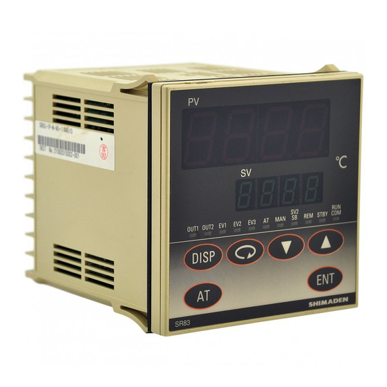
3. Front panel
3-1. Drawing and names of parts
Shows a diagram of the front panel and labels its various parts, using SR83 as an example.
3-2. Description of front panel parts
Details the functions of the PV display, SV display, action display LEDs, and key switches.
4. Screens
4-1. Power application and initial screen display
Describes the initial screens displayed upon powering on the instrument and the basic screen.
4-2. Screen configuration
Explains the division of screens into mode groups based on usage frequency for controller operation.
4-3. Key sequence
Illustrates the sequences of key presses to navigate between screens and perform operations.
4-4. How to move from screen to screen
Explains methods for navigating between mode 0 and mode 1 screens, and within screen groups.
4-5. Data change on each screen
Explains how to change data on screens and register the changes using the ENT key.
4-6. Supplementary explanation about screens
Provides supplementary explanations for specific screens like set value bias and DI settings.
5. Supplementary notes on key operation
5-1. AT
Details the Auto Tuning (AT) function, its execution, cancellation, and conditions.
5-2. Manual adjustment
Explains how to switch to manual control mode and set manual control output values.
6. Supplement
6-1. Measuring range list
Lists the available measuring ranges and corresponding codes for various input types.
6-2. Event type list
Provides a list of event types, their codes, and descriptions for setting up alarms and events.
6-3. Event standby action
Explains the standby actions for event outputs based on different settings and conditions.
6-4. Event delay time
Details how event delay time is measured and applied for event actions.
6-5. Set value Function
Describes the Set value Function (SF) for overshoot suppression in Expert PID control.
6-6. 2-output characteristics
Illustrates the characteristics of control outputs 1 and 2 for RA and DA control modes.
6-7. Error messages
Lists common error messages displayed on the PV or SV display and their meanings.
7. Specifications
DISPLAY
Details the specifications for the LED display, including accuracy, resolution, and sampling cycle.
SETTING
Covers settings like method, range, resolution, key type, ramp control, and ramp rate.
INPUT
Specifies details for various input types like Thermocouple, R.T.D., Voltage, and Current.
CONTROL (SR82: 1 output only)
Outlines control systems, PID parameters, output characteristics, and error handling for control operations.
EVENT OUTPUT (optional)
Details specifications for optional event outputs, including types, actions, and delay settings.
ANALOG OUTPUT
Specifies optional analog output characteristics, including signal types, resolution, and scaling.
HEATER BREAK ALARM
Details specifications for the optional heater break alarm, including current capacity and alarm actions.
REMOTE
Covers specifications for remote control, including setting, switching points, scaling, and signal inputs.
COMMUNICATION
Details communication specifications like type, speed, address, format, and protocol for data exchange.
DI (EXTERNAL SWITCHING) INPUT
Specifies requirements for Digital Input (DI) including number of points, types, rating, and isolation.
SET VALUE 2 (SV2)/Set Value Bias (SB)
Explains specifications for SV2 and Set Value Bias (SB) functions, including input selection and setting ranges.
OTHERS
Data storage and Environment
Specifies data storage method (EEPROM) and environmental ranges for use and storage.
Power and Standards
Details power voltage, consumption, applicable safety and EMC standards.
Dimensions and Weight
Provides external dimensions, mounting details, panel cutout sizes, and weight for each model.
Need help?
Do you have a question about the SR84 and is the answer not in the manual?
Questions and answers