Advertisement
Quick Links
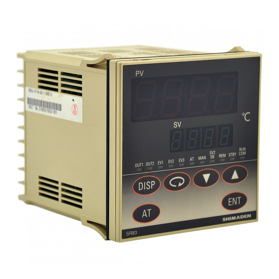
SR80 Series
Thank you for purchasing the Shimaden SR80 series digital controller.
Please check that the delivered product is the correct item you ordered. Please do not begin operating this product until
you have read this instruction manual thoroughly and understand its contents.
"Notice"
Please ensure that this instruction manual is made accessible to the
final user of this instrument.
Preface
This instruction manual is provided for those who will be involved in
the wiring, installation, operation and routine maintenance of the
SR80 series (SR82, SR83 and SR84). This manual describes the care,
installation, wiring, function and operating procedure of the SR80
series. Keep this manual at the work site during operation of the
SR80 series. While using this instrument, you should always follow
the guidance provided herein.
For matters concerning safety, potential damage to equipment and/or
facilities, additional instructions and notes are indicated by the
following headings:
Indicates matters which may result in accidents leading to injury or
death if proper attention is neglected.
WARNING
Indicates matters which may result in damage to equipment and/or
facilities.
CAUTION
Indicates that additional instructions and notes have been provided.
NOTE
The mark
represents a protective conductor terminal.
Ensure that it is grounded properly.
Matters to be attended to for safety's sake:
The SR80 series controllers are control instruments designed for
industrial use to control temperature, humidity and other physical
values. You must not employ this series for the control of any
device potentially having a serious effect on human life without
employing adequate and effective safety measures. We assume no
responsibility for any accident arising from the use of this product
without first taking effective safety measures.
WARNING
• The instrument should be installed, for example, in a control
panel to prevent its terminal portion from accidental contact with
a human body during its operation.
• The instrument should not be pulled out from its case. Never
place your hand or an electric conductor inside it as such act may
cause an electric shock resulting in serious injury or death.
• Make sure to ground the protective conductor (earth) terminal
prior to using the instrument.
CAUTION
In the event a potential failure of the instrument could cause
damage to the connected equipment, facilities or products, safety
measures such as installing a fuse or an overheating protection
device must be taken prior to the use of the instrument. We
assume no responsibility for any accident which may occur as a
result of not employing appropriate safety measures
(SR82 / SR83 / SR84)
Instruction Manual
WARNING
Digital Controller
CAUTION
• The
mark on the plate affixed to the instrument: On the terminal
nameplate affixed to the case of the instrument, the
been printed. This is to warn you of the risk of electric shock
which may result if the charger is touched while it is energized.
• In the external power circuit to be connected to the power terminal
of the instrument, a switch or a breaker as means to turn power off
must be installed. Such a switch or a breaker should be fixed
adjacently to the instrument so that it can be operated with ease,
and with an indication that it is a means to turn power off. Use a
switch or a breaker which meets the requirements of IEC60947.
• Fuse: Since the instrument does not have a built-in fuse, make sure
to install a fuse in the power circuit to be connected to the power
terminal. The fuse should be positioned between the switch or the
breaker and the instrument and be attached to the L side of the
power terminal.
Fuse rating/type: 250V AC 0.5 A/medium lagged or lagged type.
Use a fuse which meets IEC60127 requirements.
• In the wiring operation, make sure to fasten terminal connections.
• Power voltage and frequency must be within their rated ranges.
• Voltage/current of a load to be connected to the output terminal
and the alarm terminal should be within a rated range. If it goes
out of the range, a rise in temperature will reduce the product life
and/or result in problems with the product.
The output terminal should be connected with a device which
meets IEC61010 requirements.
• Voltage/current out of its specified range should not be applied to
the input terminal. It may reduce the product life and/or result in
problems with the product.
For the rated voltage/current, refer to "7. Specifications."
In case input is of voltage (mV or V) or current (4-20 mA), the
input terminal should be connected with a device which meets
IEC61010 requirements.
• The SR80 series controller is provided with a draft hole.
Take care to prevent metal or other foreign matter from entering
into it. Failure to do so may cause problems with the instrument or
even fire
• Do not block the draft hole and maintain it free from dust and dirt.
A rise in temperature or insulation failure may result in a
shortening of the product life and/or problems with the instrument.
For spaces required to be kept in its installation, see "2-3.
Drawings showing external dimensions and panel cutout."
• It should be noted that repeated tolerance tests against voltage,
noise, surge, etc. may lead to deterioration of the instrument.
• Users are prohibited from modifying the instrument and using it in
an anomalous way.
• When employing the instrument, you are requested to observe
matters to be attended to as described in the instruction manual
concerning safe and correct operation of the instrument in order to
use it safely while maintaining its reliability
It takes 30 minutes to display the correct temperature after
Note:
applying power to the digital controller. (Therefore, turn the
power on more than 30 minutes prior to the operation.)
mark has
SR80F-1IE
July 2019
Advertisement

Related Manuals for Shimaden SR80 Series


Summary of Contents for Shimaden SR80 Series
- Page 1 SR80 series (SR82, SR83 and SR84). This manual describes the care, must be installed. Such a switch or a breaker should be fixed...
- Page 2 Contents 90: 100-240V AC 10: 24V AC Power supply Page 02: 24V DC 0:None 1:Event 1. Introduction Event output 2:Event + heater break alarm (30A) *1 1-1. Check before use ............... 2 / heater break alarm 3:Event + heater break alarm (50A) *1 1-2.
- Page 3 (4) Current transformer (CT) for heater break alarm CAUTION For 0-30 A (CTL-6-S) For 0-50 A (CTL -12-S36-8) For safety’s sake and to maintain the proper functioning of the product, you should not draw it out from its case. If it is necessary to draw out the instrument, contact our office in your neighborhood (1) Machine the mounting hole by referring to the panel cutout drawings in Section 2-3.
- Page 4 (11) Connection of current transformer (CT): (3) SR84 Pass one load wire through the hole specifically provided or CT. 1 Output CT terminals on the secondary side are wired to the CT input terminal of the SR80 controller. 2 Output (1) SR82 (2) SR83 1 Output...
- Page 5 SV1 but lights if it is for SV2. (9) REM (Remote) monitor LED (green) In the SR80 series, screens are divided by the frequency of use for • Lights when rEM is selected for remote setting.
- Page 6 digit digit digit digit digit digit...
- Page 7 Initial value: 2.0 digit Setting range: 1 1000 digit Initial value: 2.0 digit Setting range: 1 1000 digit digit Initial value: 2.0 digit Setting range: 1 1000 digit Initial value: 2.0 digit Setting range: 1 1000 digit NOTE: Functions, initial values and setting ranges of the 0-25 to 0-32 screens are the same as the other PID parameters.
- Page 8 digit digit It is conditional that rE_L rE_H It is conditional that rE_L rE_H...
- Page 10 iii) The preceding screen appears every time the key is pressed. (This function of AT key works only in the mode 1 screen group.) To change data on each screen, press the key. Changed data should be registered by pressing the key.
- Page 11 (4) 1-62 AT execution point setting screen For the purpose of avoiding hunting due to a limit cycle with a On the 0-1 OUT1 control output value display screen and 0-2 set SV AT execution, a virtual SV value (AT execution point) OUT2 control output value display screen, it is possible to change is set for AT to run at a point away from the actual SV value.
- Page 12 Setting range of Initial value of event Event type Event type code event set value set value Input type Measuring range Measuring range Code Code Higher limit value of Higher limit absolute value Within measuring range *1 01 - 1800 °C - 3300 °F...
- Page 13 DISPLAY • LED display : Measured value (PV) display/ 7-segment red LED 4 digits Set value (SV) display / 7-segment green LED 4 digits Display accuracy : Within measuring range ± (0.25% FS + 1 digit) Range in which display accuracy is maintained : 23°C ±...
- Page 14 CONTROL (SR82: 1 output only) Setting resolution : 0.1% • Control system Manual automatic control One output operation: Expert PID control with auto tuning function : Balance less bump less RA (reverse characteristics) (within proportional band, though) : Heating action •...
- Page 15 • Alarm action : Heater amperage detected by external CT • Communication protocol (CT attached). : Shimaden standard protocol Alarm output ON upon detection of heater • The number of instruments allowed to be connected break while control output is ON.
- Page 16 OTHERS • Data storage : By non-volatile memory (EEPROM) • Ambient temperate / humidity ranges for use : -10 - +50 /below 90% RH (on condition that there is no dew condensation) • Temperature for storage : Between-20 and +65 •...
Need help?
Do you have a question about the SR80 Series and is the answer not in the manual?
Questions and answers