Table of Contents
Advertisement
Instruction Manual (Detailed Version)
Thank you for purchasing a Shimaden product. After making sure the product fits the desired
description, you should carefully read the instruction manual and get a good understanding of
the contents before attempting to operate the device.
Request
The instruction manual should be kept in a handy place where the end user can refer to it when necessary.
Preface
This instruction manual (detailed version) was written for those who perform wiring, installation, operation, and routine
maintenance for the SRS0 (SRS1/SRS3/SRS4/SRS5) Series.
This manual contains a description of the operating method, functions, wiring, mounting method, and precautions
when handling the SRS0 (SRS1/SRS3/SRS4/SRS5) Series (hereinafter referred to as the SRS0 Series unless a separate
description is required). You should, therefore, keep it handy to refer to it when operating and handling the device.
Be sure to observe all precautions and adhere to the procedures provided herein.
SRS0 Series
(SRS1/SRS3/SRS4/SRS5)
Digital Controller
MSRS0-E01-A
Oct. 2018
Advertisement
Table of Contents

Related Manuals for Shimaden SRS0 Series


Summary of Contents for Shimaden SRS0 Series
-
Page 1: Request
This manual contains a description of the operating method, functions, wiring, mounting method, and precautions when handling the SRS0 (SRS1/SRS3/SRS4/SRS5) Series (hereinafter referred to as the SRS0 Series unless a separate description is required). You should, therefore, keep it handy to refer to it when operating and handling the device. -
Page 2: Table Of Contents
Contents Request ..............1 8. Explanation of functions ....... 22 8-1. Events ..............22 Preface ..............1 (1) Alarm action ............... 22 1. Safety rules ............3 (2) Event standby action selection .......... 22 (3) Event selection alarm action diagrams ......22 2. -
Page 3: Safety Rules
Additional instructions or notes. WARNING The SRS0 Series digital controllers are control instruments designed for industrial use to control temperature, humidity and other physical values. You should either take appropriate safety measures or avoid using for control that could have a serious effect on human life. -
Page 4: Introduction
3) The controller is provided with tabs for mounting. Insert as is from the front surface of the panel. 4) Controllers of the SRS0 Series are designed for mounting on the panel. Be sure to mount on the panel. 5) If mounted in series, provide ventilation so ambient temperature does not exceed 50°C due to temperature rise caused... -
Page 5: External Dimensions And Panel Cutout
3-3. External dimensions and panel cutout Panel cutout SRS1 +0.6 +1.0 (48 × N - 3) If mounted horizontally N = Number of units Unit: mm SRS3 Panel cutout Min. 130 +0.8 Unit: mm SRS4 Panel cutout +1.0 +0.6 (48 × N - 3) If mounted horizontally N = Number of units Unit: mm... -
Page 6: Wiring
3-4. Wiring WARNING Be sure to turn off power before wiring. Failure to do so could result in electric shock. After wiring, do not touch terminal elements or other charged parts while conducting electricity. Failure to do so could result in electric shock. Take the following precautions when wiring: 1) Wire in accordance with the terminal layout of section 3-5 and the terminal arrangement table of section 3-6. -
Page 7: Operation Preparations
3-7. Operation preparations Before operating the controller, you should first check the wiring and carry out the following by screen group setting method. There is however no need to change the settings that have been set at the factory or already been made by the manufacturer. 1. -
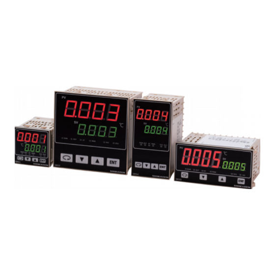
Page 8: Names And Functions Of Parts On Front Panel
4. Names and functions of parts on front panel 1) Measured value (PV) display 2) Target set value (SV) display 3) Action display 4) Operating keys Name Function 1. Measured value display LED (red) 1) Measured value (PV) display Displays current measured value (PV) on basic screen (screen 0-0). Displays type of parameter on each respective parameter display screen. -
Page 9: Parameter Diagram And Setting
5. Parameter diagram and setting 5-1. Parameter diagram The overview of the parameter diagram is as follows. The windows of the various screens are divided as follows. The number at the top left of the window is the screen No. Screen displayed when concerned optional item is added Screen always displayed by key Screen to be shown or hidden according to the setting... -
Page 10: Display When Power Is Applied
5-2. Display when power is applied When power is applied, the initial screen displays each screen for about 1 sec. and switches to the basic screen of screen group 0 as shown in the following figure. Series name ( Input type ( : thermocouple, : RTD, : Voltage [mV]) -
Page 11: Switching Screens Within Screen Group 2
(5) Switching screens within screen group 2 Each time the key is pressed the screen display switches from the various initial screens to the next screen. If pressed when the last screen is displayed, returns to the “2-0 PID initial screen.” With screen group 2, each time the keys keys only on the initial screen) are pressed, the screen is switched in the reverse direction. -
Page 12: Set Data Modification
(12) Set data modification Data is modified on the various screens by pressing the key. The modified data is entered by pressing key. 5-4. Auto return function If no key operation is conducted for 3 minutes on the various screens (with the exception of the “0-2 Output monitoring screen,”... -
Page 13: Auto Tuning (At)
(3) Auto tuning (AT) Function that automatically processes and sets parameter P.I.D. for PID control. Processing time varies according to control. 1) AT execution Pressing the key on the “0-12 AT action control screen” causes the display at the bottom to change to and all SV lamps to flash. -
Page 14: Event Setting
(5) Event setting Types of event must be set before setting event values. Modifying the event type codes however initializes setting values (data) related to events. 1) Types of event (alarm type) setting Select event type code from among non, Hd, Ld, od, id, HA, LA, So, run, rot1, StPS, PtnS, EndS, HoLd, ProG, u_SL, d_SL, or GUA on the “4-1 EV1 type setting screen”... -
Page 15: Screen Explanation And Setting Items
6. Screen explanation and setting items 0-0 Basic screen Initial values: 0 or measuring range lower limit values Setting range: Within measuring range (within SV limiter) 1-0 Initial screen 2-0 Initial screen 3-0 Initial screen 4-0 Initial screen Measured value (PV) is displayed at the top and target set value (SV) is displayed/modified on the bottom. - Page 16 PID setting screen group Setting related to multi SV (target set values) for fixed value control With the SRS0 Series, you can have 2 types of PID constants. In the case of fixed value control (FIX), target set values SV1 and 1-0 FIX setting initial screen SV2 correspond to PID1 and PID2 respectively.
- Page 17 2-7 Output PID1 lower limit output limiter setting screen Program setting Initial value: 0.0 (%) 2-0 PID initial screen Setting range: 0.0–99.9 (%) Pressing the key on the 2-0 screen switches to the program initial screen. Sets control output lower limit value. For information on output limiter, see 8-3, section (1).
- Page 18 3-8 Step 1 SV setting screen Event type code table (used by 4-1 and 4-7) Code Event action type Remark Initial value: (non) No selection Setting range: Within SV limiter (Hd) Higher limit deviation alarm EV1 initial value Sets SV value of the concerned step. (Ld) Lower limit deviation alarm EV2 initial value The display changes from [...
- Page 19 4-8 Event 2 action hysteresis setting screen 5-1 Keylock setting screen Initial value: 20 (digit) Initial value: Setting range: 1–999 (digit) Setting range: oFF, 1, 2, 3 Sets ON-OFF hysteresis of EV2 just like EV1. Locks items you don’t want to be modified. Displayed when alarm type code is Hd, Ld, od, id, HA, or LA.
- Page 20 5-9 PV filter time setting screen 5-14 Input scaling lower limit value setting screen Initial value: 0 (seconds) Initial value: 0 (digit) Setting range: 0–9999 (seconds) Setting range: -1999–9989 (digit) Used to alleviate the effect if input varies radically or noise is superimposed.
-
Page 21: Measuring Range Codes
7. Measuring range codes Select measuring range from the following table. Note: Changing the code initializes all data related to measuring range. Change setting after switching to reset mode from the 0-1 screen. Input type Code Measuring range (°C) Measuring range ( ) 0–1800°C 0–3300 -50–1700°C... -
Page 22: Explanation Of Functions
8. Explanation of functions This section contains a description of operation not covered in “5-5. Screen group 0 setting.” 8-1. Events (1) Alarm action 1) Deviation alarm Sets alarm action points for deviation of measured values (PV) from target set values (SV). For example, to trigger an alarm when measured value (PV) is 30°C or more and target set value is 20°C, the higher limit deviation alarm is set to 10°C. -
Page 23: Control Output Inverted Output
(4) Control output inverted output If equipped with contact output for control output, inverted output can be executed for control output by selecting (control output inverted output) for the event code. Output is, however, OFF for both control output and event when the power is off. -
Page 24: Control Output
8-3. Control output (1) Lower limit and higher limit limiter setting 1) Output limiter limits minimum and maximum values of control output and helps secure minimum temperature, suppress control overshoot, and achieve other objectives. 2) Lower limit value is given priority for output limiter setting. If minimum value is set above the higher limit value, the higher limit value forcibly becomes the lower limit value + 1%. -
Page 25: External Control Input (Di)
8-4. External control input (DI) Input must be retained for at least 250 ms to receive external control input of the SRS0 Series. Assignment of functions by DI input is conducted on the “4-13 DI mode setting screen.” Function assigned to DI cannot be conducted by key operation. (DI input is prioritized.) However, AT and unlatching can be conducted by key operation even if assigned to DI. -
Page 26: Change In Position Of Decimal Point
8-5. Change in position of decimal point Position of decimal point can be changed for linear input and for TC and RTD range with decimal point. You should keep in mind that operation differs for TC and RTD range when using linear input. (1) Change in position of decimal point for linear input Sets position of decimal point to be displayed. -
Page 27: Guarantee Soak (Gua)
8-7. Guarantee soak (GUA) When the operation switches from ramp step to flat step, if PV deviates from the designated guarantee soak zone, the next step does not start. This function guarantees a sufficient duration during which the flat step is executed. (1) When OFF Even when PV has yet to reach SV1, the operation switches to step 2 after the step 1 duration has elapsed. -
Page 28: Causes And Remedy Of Trouble And Errors
When the controller does not operate as intended and you suspect it may be broken, read the instruction manual and inspect once again. If there is something wrong with the controller or there is something you do not understand, contact your nearest Shimaden dealer. -
Page 29: Parameter Setting Record
10. Parameter setting record For the sake of convenience, you should record your settings and selections. Initial values for code 05 (K) are given here. Screen No. Parameter (item)/screen Initial value Setting/selection Record Basic screen (SV) Standby action (FIX) Reset action (program) Output monitoring Execution step No. - Page 30 Screen No. Parameter (item)/screen Initial value Setting/selection Record 3-26 Step 7 SV value S_07 3-27 Step 7 time t_07 3-28 Step 7 PID No. P_07 3-29 Step 8 SV value S_08 3-30 Step 8 time t_08 3-31 Step 8 PID No. P_08 3-32 Step 9 SV value...
-
Page 31: Specifications
11. Specifications Display Digital display: Measured value (PV): 7-segment red LED, 4 digits Target set value (SV): 7-segment green LED, 4 digits Action display: LED lamp display: Color Auto tuning (AT): Lights during standby (flashes during execution): Green Action display (RUN): Lights during fixed value control operation (FIX): Green Flashes during program RUN program control operation (RUN):... - Page 32 Control output Contact (Y): Contact (1a), 240V AC, 2.5 A: Resistive load/1 A: Inductive load SSR drive voltage (P): 12 V ± 1.5 V DC (max. load current 20 mA) Current (I): 4–20 mA, max. load resistance 600 Voltage (V): 0–10 V, max.
- Page 33 General specifications Data storage: By non-volatile memory (EEPROM) Operating ambient Ambient temperature: -10–50°C Humidity range: Below 90%RH (no condensation) Derating from 50°C Storage temperature: -20–65°C Over voltage category: ll Elevation: Max. 2000 m Pollution class: 2 (IEC 60664) Supply voltage: 100–240 V AC ±...
- Page 34 * With regard to the technical details of products, please contact your nearest Shimaden dealer. The contents of this manual are subject to change without notice. Temperature and Humidity Control Specialists Head Office: 2-30-10 Kitamachi, Nerima-ku, Tokyo 179-0081 Japan Phone: +81-3-3931-7891 Fax: +81-3-3931-3089 E-MAIL: exp-dept@shimaden.co.jp URL: http://www.shimaden.co.jp...
Need help?
Do you have a question about the SRS0 Series and is the answer not in the manual?
Questions and answers