Table of Contents
Advertisement
Quick Links
Digital Controller
Instruction Manual
Thank you for purchasing the Shimaden SR253 Series. Please check that the
delivered product is the correct item you ordered. Please do not begin
operating this product until you have read this instruction manual thoroughly
and understand its contents.
SR253 Series
SR253F-1BE
NOV. 2001
Advertisement
Table of Contents

Subscribe to Our Youtube Channel
Related Manuals for Shimaden SR253 Series


Summary of Contents for Shimaden SR253 Series
- Page 1 SR253 Series Digital Controller Instruction Manual Thank you for purchasing the Shimaden SR253 Series. Please check that the delivered product is the correct item you ordered. Please do not begin operating this product until you have read this instruction manual thoroughly and understand its contents.
- Page 2 Preface This instruction manual is meant for those who will be involved in the wiring, installation, operation and routine maintenance of the SR253 series. This manual describes the care, installation and wiring procedures for the operation series. Keep this manual at the work site during operation of the SR253 series.
-
Page 3: Table Of Contents
Contents Page 1. Introduction ........................................ 1-1. Check before use ....................................1) Confirmation of model codes..............................2) Checking accessories .................................. 1-2. Caution for use....................................2. Installation ........................................2-1. Installation site....................................2-2. Mounting ......................................2-3. External dimensions and panel cutout .............................. 1) SR253 External dimensions and panel cutout ..........................2) Dimension of current transformer (CT) for heater break alarm .................... - Page 4 6-6. PID group (Group 3)..................................26∼30 1) Setting of proportional band (P) ..............................2) Setting of action hysteresis (DF) ..............................3) Setting of integral time (I) ................................4) Setting of differential time (D) ..............................5) Setting of manual reset (MR)..............................6) Setting of zone ...................................
-
Page 5: Introduction
Introduction 1-1. Check before use This product has been fully checked for quality assurance prior to shipment. Nevertheless, you are requested to make sure that there is no error, damage or shortage of delivered items by confirming the model codes and checking the external view of the product and the number of accessories. 1) Confirmation of model codes Check the model codes stuck to the case of the product to ascertain if the respective codes designate what was specified when you ordered the product, referring to the following code table:... -
Page 6: Installation
Installation 2-1. Installation site Caution In the case where there is an intention to operate this product at one of the following sites, be aware that the occurrence of fire and/or other dangerous situations is considerable. Exercise caution and avoid these places when selecting an operational site. (1) Any place where inflammable or corrosive gas, dust or smoke is generated, or is filled with same. -
Page 7: Wiring
2-4. Wiring Caution • Always disconnect this product from any power source during wiring operation to prevent electrical shock. • Avoid touching the wired terminal and charged devices while supplying power. (1) Wiring operation should be done according to the instruction for the terminal arrangement in section 2-5. Exercise care that no wrong connection is made. -
Page 8: Terminal Arrangement Diagram
2-5. Terminal arrangement diagram Power supply Free supply 100~240V AC Control output For grounding Current output, Event output (option) Relay contact Voltage output, output SSR drive voltage output Output 1 Analog output (option) 100-240V AC~ A-Output 1 50/60Hz 15VA 1A 240V AC –... -
Page 9: Front Panel
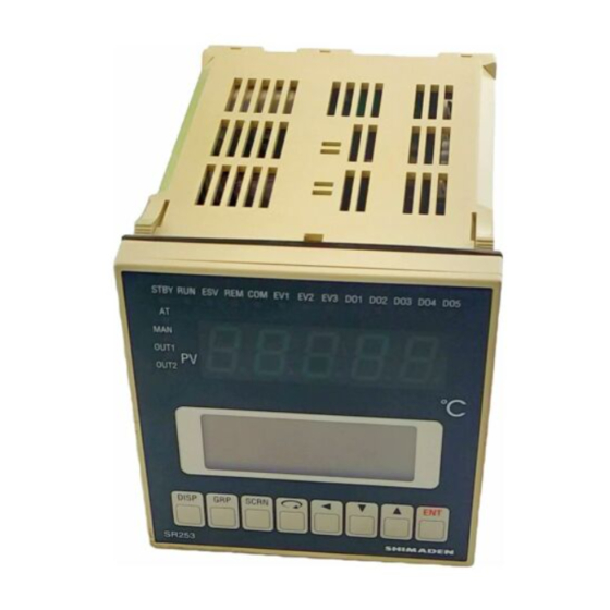
OUT 2 ° LCD (liquid crystal display) indicator * Hereinafter to be referred to as LCD. DISP GRP SCRN Key switches SR253 SHIMADEN 3-2. Instruction for front panel LED indicator Monitoring lamps (orange) (1) Measured (PV) value display (1) EV1 Displays current measured value. -
Page 10: Key Switch Operation And Description Of Screens
Key Switch Operation and Description of Screens 4-1. Application of power Upon applying power, on the LCD display the following initial screens appear for about 1.5 seconds each, followed by the initial screen of the monitor group. On these initial screens, confirm that this instrument is as specified when your original order was placed. Initial screen of the Initial screen upon power application monitor group... -
Page 11: Lcd Screen Parameter Diagram
- 7 -... -
Page 12: Functions Of The Respective Groups
Functions of the Respective Groups In Chapter 6, the basic operations of this instrument and the setting procedure are described. Follow the procedure, referring to the LCD screen parameter diagram in Chapter 5. 6-1. Lock/Initialization group (Group 8) G R P Press the key to call the LOCK/INIT screen (Group 8-0) onto display. -
Page 13: Setting Of Initialization
3) Setting of initialization (Group 8-1) Key lock: Setting range: None, Exe1, Exe2 Disp ret: 60 s Initial value: None Inital None This is the function to return registered set data to its initial value. None: No initialization. Exe1: Only the parameters shown in the following Table 1 are initialized. (For more details, see the list of parameters in Chapter 10.) Exe2: All the parameters of each group are initialized. -
Page 14: Unit/Measuring Range Group (Group 7)
6-2. Unit/Measuring range group (Group 7) (In this group, LCD screen configuration differs depending on the type of input.) Call the UNIT/RANGE screen (Group 7-0) by the use of the G R P key and press the SCRN key to move to a screen in which setting or a change is to be made. -
Page 15: Setting Of R.t.d. Type
3) Setting of R.T.D. type (Group 7-1) (This setting is only for R.T.D. input. The screen is not displayed in the case of TC or linear input.) 0.0 °C Setting range: JPt100, Pt100 PV Bias: Initial value: Pt100 PV Filt: RTD Type: Pt100 Selection between Pt100 and JPt100 as the type of sensor R.T.D. - Page 16 7) Setting of range (Group 7-2) °C Unit : Figur: Range: 200.0 A measuring range is selected from the following table. Note 1: A change in this parameter setting automatically brings Exe1 as the initialization setting into execution. Thermocouple input Measuring range Range Type of...
-
Page 17: Setting Of Decimal Point
Linear input (current or voltage) Voltage (mV) Current (mA) Voltage (V) Range No. Initial value: Voltage (mV) input; Range No.2 (0~10mV) Current (mA) input; Range No.5 (4~20mA) Voltage (V) input; Range No.6 (0~10 V) -100 8) Setting of decimal point (Group 7-3) (This setting is only for linear input. -
Page 18: Output Group (Group 6)
6-3. Output group (Group 6) G R P SCRN Press the key to call the OUTPUT screen (Group 6-0) and press the key to move to a screen in which a setting or a change is to be made. Use the key for selecting a parameter on the screen. -
Page 19: Setting Of Output Cycle
2) Setting of output cycle (Group 6-1) (This setting is only for contact or SSR drive voltage output. This screen is not displayed in the case of voltage or current output.) Out Actn: Rev Act. Setting range: 1~200 sec. Out1 Cyc: Initial value: In the case of SSR drive voltage output;... -
Page 20: Option Group (Group 5)
6-4. Option group (Group 5) [This group has setting screens of optional functions (analog output, DI, heater break alarm and communication). These screens are not shown if the optional functions are not added in your instrument.)] G R P Press the key to call the OPTION screen (Group 5-0) and move to a screen in which setting or a change to be made by the use of the key. -
Page 21: Matters Related To The Setting Of Analog Output
Matters Related to the Setting of Analog Output 1) Setting of analog output assignment (Group 5-1~2) Ao1 Mode: Measuring range: PV, SV, DEV, OUT1, OUT2 0.000 °C Ao1 Sc_L: Initial value: Analog output 1; PV 50.000 °C Ao1 Sc_H: Analog output 2; SV Ao2 Mode: 0.000 °C Ao2 Sc_L:... -
Page 22: Matters Related To Setting Of Di
Matters Related to Setting of DI 3) Setting of DI assignment (Group 5-3) Measuring range: 8 types as shown in the following table. DI1: NOP [OFF] Initial value: DI1~4; NOP DI2: NOP [OFF] DI3: NOP [OFF] DI4: NOP [OFF] For the purpose of carrying out external control by means of no-voltage contact signals externally, actions to be executed can be selected from the following 8 types and may be assigned to DI1 through 4: Type Description of action... -
Page 23: Matters Related To Setting Of Heater Break Alarm
Matters Related to Setting of Heater Break Alarm 4) Display of CT current (Group 5-4) (Heater break alarm and heater loop alarm are usable when control output 1 is of contact (Y) or SSR drive voltage (P). They cannot be used if control output 1 is of current (I) or voltage (V).) ↓... -
Page 24: Setting Of The Heater Break/Loop Alarm Mode
7) Setting of the heater break/loop alarm mode (Group 5-4) Setting range: LOCK, REAL CT Current [ 10.0A] Initial value: LOCK HBA Curr: HLA Curr: HA Mode : LOCK You can select either the lock mode or the real mode for alarm output. Lock mode (LOCK): Once alarm is output, the alarm output is locked (fixed) and the alarm keeps being output even if the CT current level returns to normal. -
Page 25: Event/Do Group (Group 4)
6-5. Event/DO group (Group 4) (The screens of this group are not displayed when EV and DO are not set as optional on the screens concerned. ) On the description of each setting, explanation is made on EV but this explanation applies to DO as well. G R P Press the key to call the EVENT/DO screen (Group 4-0) and move to a screen in which setting or a change is to be made by the use of the... -
Page 26: Setting Of Event Action And Do Action Mode
1) Setting of event action and DO action mode (Group 4-1A~4-8A) EV 1 Mode: DEV High Set Point: 25.000 °C ↓ 0.020 °C Diffrnt1 : DO 5 Mode: Stanby Setting range: 19 types listed below (Nevertheless, HBA and HLA can be set only when the instrument has the optional function of heater break alarm. -
Page 27: Setting Of Action Point
2) Setting of action point (Group 4-1A~4-8A) (The setting is required only when any of the event types (1)~(8) is set for event action and DO action modes. When any of the event types (9)~(19) is set, these screens are not displayed.) EV 1 Setting range: DEV High ;... -
Page 28: Setting Of Delay Time
4) Setting of delay time (Group 4-1B~4-8B) (The setting is required only when any of the event types (1)~(8) is set for event action and DO action modes. When any of the event types (9)~(19) is set, these screens are not displayed.) EV 1 Setting range: OFF, 1~9999 unit Delay... -
Page 29: Setting Of Inhibit Action
5) Setting of inhibit action (Group 4-1B~4-8B) (The setting is required only when any of the event types (1)~(8) is set for event action and DO action modes. When any of the event types (9)~(19) is set, these screens are not displayed.) EV 1 Setting range: ON, OFF Delay... -
Page 30: Pid Group (Group 3)
6-6. PID group (Group 3) (The configuration of this group differs depending on whether the instrument has one output or two outputs as control output.) ◊ As this instrument can work with multi-PIDs corresponding to multi-SVs, PID constants can be registered at PID Nos. corresponding to SV Nos. ◊... -
Page 31: Setting Of Proportional Band (P)
1) Setting of proportional band (P) (Group 3-1A~) 3.0% Setting range: OFF, 0.1~999.9% 120s Initial value: 3.0% 0.0% ↓ Zone: 0.0°C A rate (%) of a change in control output to measuring range is set. Control output changes in proportion to difference (deviation) between measured (PV) value and set (SV) value. -
Page 32: Setting Of Manual Reset (Mr)
5) Setting of manual reset (MR) (Group 3-1A~) 3.0% Setting range: -50.0~+50.0% Initial value: 0.0 % for 1 output type 0.0% -50.0 % for 2 output type ↓ Zone: 0.0°C This is the function to make correction manually while watching the result of controlling offset produced by carrying out control action with P or P+D when OFF is set for I (integral time). -
Page 33: Setting Of Dead Band
7) Setting of dead band (Group 3-1B~) (This setting is only for the two output type. The screen is not displayed in the case of one output.) Setting range: -20000~20000 unit 3.0% Initial value: 0 unit 120s ↓ 0.0°C To carry out two output control, by taking characteristics of the object of control and the energy-saving effect into account, action range of control output 2 can be set as shown in the following action characteristic diagrams. -
Page 34: Setting Of Zone Hysteresis
9) Setting of zone hysteresis (Group 3-11) Setting range: 0~10000 unit Zone HYS: 2.0°C Initial value: 20 unit Zone PID: Singl PID: 0.40 For set zone values, the following hysteresis can be set. This hysteresis applies to all the set zone values, however. Set value (SV) PID No.3 zone value Hysteresis... -
Page 35: Remote/Ramp Group (Group 2)
6-7. SV/Remote/Ramp group (Group 2) G R P SCRN Press the key to call SV screen (Group 2-0). Then press the key, and the screen of SV No. currently in use is displayed. (This functions only when the screen 2-0 has been called from another group. In case the key is pressed in the same group to return to G R P the initial screen of the group and the... -
Page 36: Setting Of Sv Limits
2) Setting of SV limits (Group 2-12) 0.000 °C Setting range: Within measuring range but SV Limt_L < SV Limit_H SV Limt_L: 50.000 °C Initial value: SV Limt_L; Lower limit value of measuring range SV Limt_H: SV Limt_H; Higher limit value of measuring range SV Select: 0.000 °C SV Limt_L:... -
Page 37: Setting Of Remote Scale
6) Setting of remote scale (Group 2-13A) 0.000 °C Setting range: Within measuring range (RSV) REM Bias: 0.00~100.00% (CTRL) REM Filt: but REM Sc_L ≠ REM Sc_H 0.000 °C REM Sc_L: ↓ 50.000 °C Initial value: REM Sc_L; Lower limit of measuring range (RSV) REM Sc_H: 0.00% (CTRL) REM Sc_H;... -
Page 38: Setting Of Remote Tracking
On External Control Operation REM Sc_L < Sc_H REM Sc_L > Sc_H -0.5 +0.5 +0.5 -0.5 +0.5×P.B % +0.5×P.B % REM_OUT1 (%) REM_OUT1 (%) -0.5×P.B % -0.5×P.B % Sc_L Sc_H Sc_H Sc_L 100% 100% (0V) (0V) (10V) REM voltage input (10V) REM voltage input (4mA) -
Page 39: Setting Of Remote Proportional Coefficient
9) Setting of remote proportional coefficient (Group 2-13A) (This parameter is valid only when REM Mode:CTRL.) Setting range: OFF, 0.1~999.9% REM Mode: Initial value: OFF REM Trck: REM P.B : REM Time: Remote proportional coefficient (REM P.B) is the parameter for setting a percentage at which a value whose range is specified in Remote Scale is output to REM_OUT1. -
Page 40: Setting Of Ramp Unit
12) Setting of ramp unit (Group 2-14) RAMP Down: Setting range: Unit/Sec., Unit/Min. RAMP Up Initial value: Unit/Min. RAMP Unit: °C/Min RAMP Rate: X1 In this screen, second (Sec.) or minute (Min.) is selected as the unit of the rate of change. Note 1: The unit of ramp time can be changed during execution of ramp control. -
Page 41: Control Group (Group 1)
6-8. Control group (Group 1) G R P SCRN Press the key to call the CONTROL screen (Group 1-0). Then, press the key to move to a screen in which a setting or a change is to be made. Use the key to select a parameter on the screen. -
Page 42: Setting Of Auto Tuning Point
2) Setting of auto tuning point (Group 1-1) Setting range: 0~10000 unit Auto Tuning: STOP 0.000 °C Initial value: 0 unit AT Point: If you want to avoid hunting resulting from limit cycle with set SV value in executing auto tuning, set a hypothetical SV value (AT point) to carry out auto tuning at a point apart from the actual SV value. -
Page 43: Execution/Standby Of Control
4) Execution/standby of control (Group 1-2) Control A/M: AUTO Setting range: EXEC, STANBY Control Exe: EXEC Initial value: EXEC Ramping Run: STOP Operation : LOCAL This is the function to keep control output, event output and external output on standby and to start control only after input is steadied. STANBY : Control is out of operation and control output is set at 0%. -
Page 44: Monitor Group (Group 0)
6-9. Monitor group (Group 0) In the monitor group, the states of set value, deviation value and control output are displayed in three screens. In the initial screen of the monitor group (Group 0-0), switch between SV value setting and SV No. in execution is possible. In case a screen of any other group than the monitor group is on display, press the D I S P key to call the initial screen of monitor group (Group... -
Page 45: Switching To Remote Sv
4) Switching to Remote SV Switching to Remote SV is available on the initial screen of monitor group. (group 0-0) In the SV No. in execution of switching, select by using the key as 01→02→······→10→REM. Resistering by key allows you to switch. However, when remote function is assigned to DI, switching with the SV No. in execution E N T cannot be done. -
Page 46: External Input/Output
External Input/Output (Option) External Input Selection of local SV No. and external control by assigning to DI can be carried out by means of no-voltage contact input signal from external or open collector input signal. V=5V 1 max=2.4mA 1 max Contact Open collector 1. -
Page 47: Connecting Devices For Instrument Terminals
SV SEL1 SELECTOR SV No. SV SEL2 SV SEL4 SV SEL8 KA251 SHIMADEN Model: KA251 Unit: mm H48×W48×D100mm Exterior view Diagram of terminal arrangement Panel cut-out size For switching SV No. externally, use this device together with the above-mentioned 24-pin plug attached with connection cords. -
Page 48: Error Messages (Pv Display)
Error Messages (PV Display) 9-1. Problems found in check-up upon application of power Error message Cause ROM problem RAM problem Note 1: If any of the messages shown in the table are displayed, repair EEPROM problem or replacement will be necessary. Turn the power off as quickly as possible and call the agent or our business office. -
Page 49: List Of Parameters
List of Parameters Control Group (Group 1) Control Group Code Description of function Setting range Initial value Execution/stop of auto tuning STOP STOP Auto Tuning EXEC [Key Lock 2] Auto tuning point 0~10000 unit 0 unit AT Point Control Group Code Description of function Setting range... - Page 50 SV/Remote/Ramp Group (Group 2) SV Group Code Description of function Setting range Initial value Target set value 1 Within set value limiter 0 unit SV_No. 1 Target set value 2 SV_No. 2 Target set value 3 SV_No. 3 Target set value 4 SV_No.
- Page 51 PID Group (Group 3) PID Group Code Description of function Setting range Initial value Proportional band (%) OFF, 0.1~999.9% 3.0% Integral time (sec.) OFF, 1~6000 sec. 120 sec. Differential time (sec.) OFF, 1~3600 sec. 30 sec. Action hysteresis 1~9999 unit 20 unit Zone Setting of zone...
- Page 52 EVENT/DO Group (Group 4) EVENT/DO Code Description of function Setting range Initial value Group Action mode DEV High EV1: DEV High Mode Event 1 DEV Low EV2: DEV Low Event 2 DEV Outside EV3: Scale Over Event 3 (HBA) DEV Inside DO 1 PV High DO1: Auto Tuning...
- Page 53 OPTION Group (Group 5) OPTION Code Description of function Setting range Initial value Group Analog Out1 Analog output 1 assignment Ao1 Mode OUT1 OUT2 Ao1 Sc_L Analog output 1 scaling Within measuring range (PV and SV) Lower limit value of -100.0~100.0% (DEV) measuring range 0~100.0% (OUT1 and OUT2),...
- Page 54 OPTION Code Description of function Setting range Initial value Group Communication memory mode Control code (Standard mode only) STX_ETX_CR STX_ETX_CR CTRL STX_ETX_CRLF @_:_CR Check sum (Standard mode only) Add-two's cmp NONE [Key Lock 1] DELY Delay 0~99 Output Group (Group 6) OUTPUT Code Description of function...
- Page 55 Unit/Measuring Range Group (Group 7) UNIT/RANGE Code Description of function Setting range Initial value Group PV bias -9999~9999 unit 0 unit PV Bias PV filter OFF, 1~300 PV Filt Pt Type Type of R.T.D. Pt100 Pt100 JPt100 Reference junction compensation INTER INTER CJ Comp...
-
Page 56: Sheet For Recording Set Parameters
Sheet for Recording Set Parameters SV/Remote/Ramp setting group (Group 2) and PID setting group (Group 3) User set value Multi-SV No. SV set value PID set value (output 1) ZONE Lmt_L Set value for output limits (output 1) Lmt_H PID set value (output 2) ZONE Lmt_L Set value for output limits (output 2) - Page 57 EVENT/DO setting group (Group 4) Item User set value Item User set value EV 1 Mode DO 1 Mode Set Point Set Point Diffrntl Diffrntl Delay Delay Inhibit Inhibit Charact Charact EV 2 Mode DO 2 Mode Set Point Set Point Diffrntl Diffrntl Delay...
-
Page 58: Specifications
Specifications 1. Display • LED display: 7-segment green LED 5 digits/height of character 14 mm Measured value (PV) display • LCD display: 128×32 full dot matrix liquid crystal display (Basic display 21 digits, 4 lines with LED back light) Set value (SV), SV No. display and set parameter display •... - Page 59 • R.T.D.: JIS Pt/JPt 3-wire type (multi range) Lead wire tolerable resistance: 5Ω max./wire Amperage: Approx. 1mA • Voltage: -10~10, 0~10, 0~20, 0~50, 10~50, 0~100, -100~100mV DC or -1~1, 0~1, 0~2, 0~5, 1~5, 0~10, -10~10V DC (Multi input, programmable scaling) Input impedance: 500kΩ...
- Page 60 • Manual control Output setting range: Y, P: 0.0~100.0%, I,V: -5.0~105.0% Output resolution: 0.1% Auto/manual switch: Balanceless bumpless action (within proportional band range) Switching by front key switch or external control input (DI) • Isolation: Insulated between control output and various inputs/outputs and system (not insulated between 1 output and 2 outputs) 5.
- Page 61 7. Heater Break Alarm (Option) • Alarm action: Heater amperage detected by externally attached CT (special CT provided) (single phase) Alarm output On upon detection of heater break while control output is On. Alarm output On upon detection of heater loop alarm while control output is Off. •...
- Page 62 10. General Specification • Data storage: By non-volatile memory (EEPROM) • Operating ambient temperature/humidity range: -10~50°C/90% RH max. (no dew condensation) • Storing temperature: -20~+65°C • Supply voltage: 100V-240V AC±10% (50/60Hz) • Power consumption: Maximum 15 VA • Input noise removal ratio: Normal mode: 60 dB minimum (50/60Hz) Common mode: 140 dB minimum (50/60Hz)
- Page 63 - 59 -...
- Page 64 The contents of this manual are subject to change without notice. Temperature and Humidity Control Specialists Head Office: 2-30-10 Kitamachi, Nerima-Ku, Tokyo 179-0081 Japan Phone: +81-3-3931-7891 Fax: +81-3-3931-3089 E-MAIL: exp-dept@shimaden.co.jp URL: http://www.shimaden.co.jp PRINTED IN JAPAN - 60 -...
Need help?
Do you have a question about the SR253 Series and is the answer not in the manual?
Questions and answers