Sign In
Upload
Download
Table of Contents
Contents
Add to my manuals
Delete from my manuals
Share
URL of this page:
HTML Link:
Bookmark this page
Add
Manual will be automatically added to "My Manuals"
Print this page
×
Bookmark added
×
Added to my manuals
Manuals
Brands
Shimaden Manuals
Controller
SR1 Series
Instruction manual
Shimaden SR1 Series Instruction Manual
Hide thumbs
Also See for SR1 Series
:
Instruction manual
(8 pages)
1
2
3
4
5
6
7
8
9
10
11
12
page
of
12
Go
/
12
Contents
Table of Contents
Bookmarks
Advertisement
Table of Contents
1
Safety Rules
2
About Installation
3
Replacement Part
4
Names and Functions of Parts on Front Panel
5
Outline of Specifications
6
Before Starting up
7
Maintenance and Troubleshooting
Download this manual
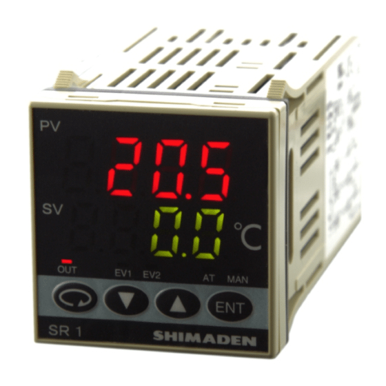
SR1, SR3, SR4 Series Digital Controller
Instruction Manual
Please do not begin operating this product until you have read this instruction manual thoroughly and you
understand its contents.
SR1F-1KE
Nov. 2017
Table of
Contents
Previous
Page
Next
Page
1
2
3
4
5
Advertisement
Table of Contents
Need help?
Do you have a question about the SR1 Series and is the answer not in the manual?
Ask a question
Questions and answers
Related Manuals for Shimaden SR1 Series
Controller Shimaden SR1 Series Instruction Manual
Digital controller (8 pages)
Controller Shimaden SR90 series Instruction Manual
Communication interface manual (16 pages)
Controller Shimaden SR90 Series Instruction Manual
Digital controller (26 pages)
Controller Shimaden SR90 Series Instruction Manual
Digital controller (32 pages)
Controller Shimaden SR62 Instruction Manual
Sr60 series. digital controller (14 pages)
Controller Shimaden SR23 series Instruction Manual
Digital controller (154 pages)
Controller Shimaden SR23 Series Instruction Manual
Digital controller (139 pages)
Controller Shimaden SRS0 Series Instruction Manual
Digital controller (34 pages)
Controller Shimaden SR73A Series Instruction Manual
Digital controller (16 pages)
Controller Shimaden SR83 Instruction Manual
Digital controller (16 pages)
Controller Shimaden SRS10A Series Instruction Manual
Digital controller (36 pages)
Controller Shimaden SRS12A Instruction Manual
Digital controller (36 pages)
Controller Shimaden SRS14A Instruction Manual
Digital controller (36 pages)
Controller Shimaden SRS10 Series Instruction Manual
Digital controller (32 pages)
Controller Shimaden SRS11 Series Instruction Manual
Digital controller (32 pages)
Controller Shimaden SRS13 Series Instruction Manual
Digital controller (32 pages)
This manual is also suitable for:
Sr3 series
Sr4 series
Table of Contents
Print
Rename the bookmark
Delete bookmark?
Delete from my manuals?
Login
Sign In
OR
Sign in with Facebook
Sign in with Google
Upload manual
Upload from disk
Upload from URL


Need help?
Do you have a question about the SR1 Series and is the answer not in the manual?
Questions and answers