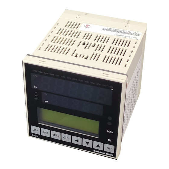
Shimaden SR23 series Instruction Manual
Digital controller
Hide thumbs
Also See for SR23 series:
- Instruction manual (139 pages) ,
- Installation manual (4 pages) ,
- Quick reference (4 pages)
Table of Contents
Advertisement
Quick Links
SR23 Series
Digital Controller
Instruction Manual
(Detailed version)
Servo output
(Positioning proportional control)
Thank you for purchasing the Shimaden SR23 Series Digital
Controller. Check that the delivered product is the correct item you
ordered. Do not begin operating this product until you have read and
thoroughly understood the contents of this Instruction Manual
(Detailed version).
MSR023-E03-C
Dec. 2017
Advertisement
Table of Contents

Related Manuals for Shimaden SR23 series


Summary of Contents for Shimaden SR23 series
- Page 1 (Detailed version) Servo output (Positioning proportional control) Thank you for purchasing the Shimaden SR23 Series Digital Controller. Check that the delivered product is the correct item you ordered. Do not begin operating this product until you have read and thoroughly understood the contents of this Instruction Manual (Detailed version).
- Page 3 Make sure that this Instruction Manual is given to the final user of the device. Keep this manual at the work site during operation of the SR23 Series. Preface This Instruction Manual describes the basic functions and how to use "Servo output"...
- Page 4 Caution To avoid damage to connected peripheral devices, facilities or the product itself due to malfunction of this device, safety countermeasures such as proper installation of the fuse or installation of overheating protection must be taken before use. No warranty, express or implied, is valid in the case of use resulting in an accident without having taken the proper safety countermeasures.
- Page 5 QCS002 250Ω±0.1% Relay Unit AP2MC Converts open collector output to 2-point contact. SV No. Selector KA251 BIN code, switchable between SV1 to SV10 Setup tool “Parameter Assistant” /USB driver can be downloadable FREE from the Shimaden website shown as below.
- Page 6 Standard 4 DI, 5 DO (SV No. switching not available) (DI/DO) *2 10 DI, 9 DO (SV No. switching available) 0 None 5 RS-485 SHIMADEN protocol 9. Communication function / MODBUS (ASCII / RTU) protocol 7 RS-232C Standard firmware 10. Remarks...
-
Page 7: Table Of Contents
Contents 1 INSTALLATION & WIRING ..............1 Installation Site .................... 1 External Dimensions and Panel Cutout ............1 Mounting ...................... 2 Rear Terminal Arrangement Diagrams ............3 Wiring ......................5 (1) Precautions for wiring ..................5 (2) Connection example ..................6 2 NAMES &... - Page 8 Unit ......................26 Decimal Point Position ................26 (1) Decimal point position ..................26 (2) Switching the lowest digit past the decimal point ..........27 Cold Junction Compensation ..............28 (1) Thermocouple cold junction compensation ............. 28 8 I/O AUXILIARY SETTINGS ............... 29 PV Compensation Value ................
- Page 9 10 PID SETTING ..................45 10-1 Proportional Band (P) ................45 10-2 Integral Time (I) ..................45 10-3 Derivative time (D) ..................46 10-4 Manual Reset (MR) ................... 46 10-5 Action Hysteresis (DF) ................47 10-6 Set Value Function (SF) ................47 10-7 Output Limit Value (OUT1L to OUT1H) .............
- Page 10 viii 12-3 Communication ..................64 (1) Setting communication ..................64 (2) Communication mode (COM) ................65 13 SERVO SETUP ................. 67 13-1 Overview of Setup Procedure ..............67 13-2 Control Output (Servo Output) ..............68 (1) Action characteristics ..................68 (2) Output at standby ....................
- Page 11 15-2 Operations in Basic Screen ............... 91 (1) Switching the SV No..................91 (2) Output monitor screen ..................91 16 OPERATIONS DURING CONTROL ..........93 16-1 Monitoring Control ..................93 (1) Basic screen ....................93 (2) Output monitor ....................93 16-2 Switching the Execution SV No.
- Page 12 18-8 Control Output Screen Group (group 6) ..........118 18-9 Unit/Range Screen Group (group 7) ............119 18-10 Lock, etc Screen Group (group 8) ............120 19 PARAMETER SETUP RECORD SHEETS ........121 19-1 Product Model Code ................121 19-2 SV Parameters ..................
- Page 13 This page left intentionally blank.
- Page 14 LCD Flow Chart The following figure shows how to progress through the LCD screen hierarchy on this device. Standard screen Screens that are always displayed Screens that are displayed depending Non-standard on options/setup values. screen Group 1 Group 3 Group 4 Group 0 Group 2 Control execution...
- Page 15 Ao2_L: 0.0℃ Ao2_H: 800.0℃ Sc_H: 100.0% SCRN SCRN UNIT:% DP: XXXX.X SCRN SCRN SCRN SCRN PROT: SHIMADEN SQ.Root: ON ADDR: Low Cut: 1.0% BPS : 9600 MEM : EEP SCRN SCRN SCRN SCRN COM DATA: PMD: ON PARI: EVEN STOP: A 1: 0.00%...
- Page 16 This page left intentionally blank.
-
Page 17: Installation & Wiring
1 INSTALLATION & WIRING INSTALLATION & WIRING Installation Site Caution Do not use this device in the following sites. Doing so might result in malfunction or damage to this device and in some cases cause fire and/or dangerous situations. Locations that are filled with or generate inflammable gas, corrosive gas, dirt and dust, smoke, etc. -
Page 18: Mounting
1 INSTALLATION & WIRING Panel cutout or more Unit: mm Mounting Caution To ensure safety and maintain the functions of this device, do not disassemble this device. If this device must be disassembled for replacement or repair, contact your dealer. Follow the procedure below to mount this device on a panel. -
Page 19: Rear Terminal Arrangement Diagrams
1 INSTALLATION & WIRING Rear Terminal Arrangement Diagrams Contact output model Terminal Terminal Symbol Description Symbol Description Analog output 1 External control output (option) Open collector output Analog output 2 or (option) Sensor power supply (option) Remote input External input DI5 to DI10 (option) Thermocouple input... - Page 20 1 INSTALLATION & WIRING Grounding (internal shorting across Feedback potentiometer terminals) input Open A receiving resistor of 1/2W 250 Control Output 0.1% is attached across input Close terminals (7-10) for use for the 0 to 20 mA, and 4 to 20mA inputs. Darlington External output...
-
Page 21: Wiring
1 INSTALLATION & WIRING Wiring (1) Precautions for wiring Caution To prevent electric shock, always turn off and disconnect this device from the power supply before starting wiring. Do not touch wired terminals or charged parts with your hands while the power is supplied. -
Page 22: Connection Example
1 INSTALLATION & WIRING (2) Connection example This instrument is designed to connect a control motor directly via the terminal M1, M2, and M3. AC relay may have built-in CR absorber to protect its contact. DC relay use is recommended, because if AC relay is used as auxiliary relay, it cannot recover from magnetic excitation. -
Page 23: Names & Functions Of Parts On Front Panel
2 NAMES & FUNCTIONS OF PARTS ON FRONT PANEL NAMES & FUNCTIONS OF PARTS ON FRONT PANEL HLD MAN EV1 EV2 EV3 DO1 DO2 DO3 DO4 DO5 EXT COM ① PV display ⑤ LED indicators SV display ② OPEN CLOSE ⑥... - Page 24 2 NAMES & FUNCTIONS OF PARTS ON FRONT PANEL Front panel key switches DISP (Display key) Displays the basic screen. (Group key) Changes the screen group. Or, returns to the screen group top screen. SCRN (Screen key) Switches the parameter display screen in a screen group.
- Page 25 2 NAMES & FUNCTIONS OF PARTS ON FRONT PANEL Status lamps STBY green Blinks when output is set to standby (STBY=ON) by control execution/standby. green Blinks during execution of ramp control, and lights while ramp control is paused. green Blinks when control output is set to manual operation (MAN). green Lights when remote setting (REM) is set in SV No.
- Page 26 2 NAMES & FUNCTIONS OF PARTS ON FRONT PANEL This page left intentionally blank.
-
Page 27: Basic Operations
3 BASIC OPERATIONS BASIC OPERATIONS Power ON When the power is turned ON, the basic screen is displayed after the initial screen is displayed on the LCD for about three seconds. When the SR23 is powered ON for the first time, check on screen to make sure that this device is the one you ordered. -
Page 28: Switching Lcd Screen Display And Moving The Cursor
3 BASIC OPERATIONS Switching LCD Screen Display and Moving the Cursor Switching the screen display For details on moving between screens, see "LCD Flow Chart" in the preface. The operation screens of this device are configured so that screens are displayed in order from the most frequently used screen in regular use. -
Page 29: Changing And Registering Data
3 BASIC OPERATIONS Changing and Registering Data Basically, set up and change parameters while confirming the LCD screen display. Entering numerical values 1. When there are two or more parameters, press the key to move the cursor ( ) to the parameter to be changed. 2. -
Page 30: Selecting Setup Items
3 BASIC OPERATIONS Selecting setup items The settings of parameters marked by a key mark cannot be changed. 1. When there are two or more parameters, press the key to move the cursor ( ) to the parameter to be changed. 2. -
Page 31: Control Function Block Diagrams
Ramp control adapter REM bias Ten-segment Linearization linealization Local/REM switching PV filter Infrared interface REM tracking PV slope SHIMADEN standard protocol Feedback SV limit ON/OFF PV bias Execution PV Execution SV Execution/standby, processing of computations, front panel infrared communications Analog Analog... - Page 32 4 CONTROL FUNCTION BLOCK DIAGRAMS This page left intentionally blank.
-
Page 33: Setup
5 SETUP SETUP Parameter Setup Procedure Follow the procedure below to set up this device or change device settings when you use this device for the first time, change the operation parameters during use, or the control target device has been changed, for example. Caution With some operations, when you initialize this device, all parameter settings return to their factory defaults. - Page 34 5 SETUP 8. Servo Functions Settings After basic parameters are set or changed, set servo relating parameters. For details, see “Chapter 13”. 9. Key Lock Setting. After parameters including option functions are set or changed, set the key lock as necessary to prevent inadvertent operation. For details, see "Chapter 14."...
-
Page 35: Output Specification & Key Lock
6 OUTPUT SPECIFICATION & KEY LOCK OUTPUT SPECIFICATION & KEY LOCK Perform the following as necessary. Confirming the Output Specification The output specification is displayed at the bottom row of the key lock, setting screen (No.8-1). To call up the LOCK, etc. screen group (group 8) from the basic screen, press the key. -
Page 36: Releasing The Key Lock
6 OUTPUT SPECIFICATION & KEY LOCK Releasing the Key Lock Key lock screen display To call up the LOCK, etc. screen group (group 8) from the basic screen, press the key. Press the key in the LOCK, etc. screen group to switch to the screens for making SCRN and changing setups. -
Page 37: Input Settings
7 INPUT SETTINGS INPUT SETTINGS Infrared Communication Allow the infrared communication using S5004 (Infrared Communication Adapter, selling separately). IR COM should be ON before the instrument parameters are set via infrared communication. Parameter Assistant Software is also used for this communication. For details, see “Parameter Assistant Instruction Manual”... -
Page 38: Measuring Range
7 INPUT SETTINGS Measuring Range Before performing setup or changes to the setup, set control action to the standby mode (STBY: ON). For details on control standby operation, see "16-8 Control Standby (STBY)." Range setting Set the code No. to RANGE referring the Measuring Range Code Table below. Setting range 01 to 19, 31 to 58, 71 to 77, 81 to RANGE: 06(K3) -
Page 39: Range Scaling
7 INPUT SETTINGS Range scaling Set the measuring range (scaling) when the selection range is voltage input and current input (corresponding to code Nos.71 to 77, 81 to 87). Sc_L is scaling of the lower limit side of PV, and Sc_H is scaling of the higher limit side of PV. Before performing setup or changes to the setup, set control action to the standby mode (STBY: ON). - Page 40 7 INPUT SETTINGS Measuring Range Code Table Input Type Sensor Type Code Symbol Measuring range Measuring range 0.0 to 1800.0 °C 0 to 3300 °F 0.0 to 1700.0 °C 0 to 3100 °F 0.0 to 1700.0 °C 0 to 3100 °F -100.0 to 400.0 °C -150.0 to 750.0 °F 0.0 to 400.0 °C...
- Page 41 7 INPUT SETTINGS Input Type Sensor Type Code Symbol Measuring range Measuring range JPt 1 -200.0 to 500.0 °C -300.0 to 900.0 °F JPt 2 -100.00 to 100.00 °C -150.0 to 200.0 °F JPt 3 -100.0 to 300.0 °C -150.0 to 600.0 °F JPt 4 -60.00 to 40.00 °C -80.00 to 100.00 °F...
-
Page 42: Unit
7 INPUT SETTINGS Unit Select the unit to be used in the preset measuring range. Before performing setup or changes to the setup, set control action to the standby mode (STBY: ON). For details on control standby operation, see "16-8 Control Standby (STBY)." Only temperature (°C, °F) can be selected for RTD and TC input. -
Page 43: Switching The Lowest Digit Past The Decimal Point
7 INPUT SETTINGS Switching the lowest digit past the decimal point The lowest digit past the decimal point of measuring ranges determined by the range setting can be set. Note, however, that this function cannot be used for measurement ranges without digits past the decimal point. -
Page 44: Cold Junction Compensation
7 INPUT SETTINGS Cold Junction Compensation Thermocouple cold junction compensation Set whether to perform cold junction compensation during TC input (corresponding to code Nos. 01 to 19) internally or externally. Normally, set to internal compensation. Set to external compensation when greater accuracy is required. -
Page 45: O Auxiliary Settings
8 I/O AUXILIARY SETTINGS I/O AUXILIARY SETTINGS PV Compensation Value PV bias This item is used to compensate for error in the indicated temperature, for example, in the sensor/connected peripherals. Setting range -10000 to 10000 digit PV Bias: Initial value 0 digit PV Filter: PV Slope: 1.000... -
Page 46: Square Root Extraction Operation
8 I/O AUXILIARY SETTINGS Square Root Extraction Operation Signals having square root characteristics such as in the measurement of flow rates can be linearized. This item is set during voltage input and current input. This item is not displayed in the case of RTD or TC input. Enabling the square root extraction operation The square root extraction operation function is valid when SQ.Root is set to ON. -
Page 47: Ten-Segment Linearizer Approximation
8 I/O AUXILIARY SETTINGS Ten-Segment Linearizer Approximation Enabling ten-segment linearizer approximation This setting is only for voltage input and current input. This function performs linearization based upon ten-segment approximation when the PV input is a non-linear signal. Setting range OFF, ON PMD OFF Initial value 1... - Page 48 8 I/O AUXILIARY SETTINGS Ten-segment linearizer setting (example) In the following figure, A1, B1 to A6, B6 are used to set input points with four intermediate points. For before A1 and from A6 onwards, the ramps of (AI, B1) to (A2, B2) and the ramps of (A5, B5) to (A6, B6) are applied.
-
Page 49: Compensating Analog Output
8 I/O AUXILIARY SETTINGS Compensating Analog Output Error that occurs in analog output can be compensated. 1. Release the key lock if it is applied. For details on how to release the key lock, see "6-2 Releasing the Key Lock." 2. - Page 50 8 I/O AUXILIARY SETTINGS This page left intentionally blank.
-
Page 51: Sv Value & Remote Sv Value
9 SV VALUE & REMOTE SV VALUE SV VALUE & REMOTE SV VALUE Setting the SV Value SV limiter The SV limiter is used to prevent input of wrong target set values. Set the lower limit value (SV L) and higher limit value (SV H) of the set value (SV) setting range. -
Page 52: Setting The Remote Sv Value
9 SV VALUE & REMOTE SV VALUE Setting the Remote SV Value Monitoring the remote SV The remote input signals are displayed in the REM set value monitor screen corresponding to the measuring range. The remote SV value cannot be set by operating the front panel keys. 2-11 R E M : ℃... -
Page 53: Remote Mode
9 SV VALUE & REMOTE SV VALUE Remote mode Various computations can be performed on remote signals, and the result taken as the remote SV. In the RSV mode, the "Ratio:" row in the following screen is not displayed. 2-13 Setting item RSV, RT REM Track: NO... -
Page 54: Setting The Remote Sv Compensation Value
9 SV VALUE & REMOTE SV VALUE Setting the Remote SV Compensation Value Remote ratio This item is valid only when RT is selected in the Remote Mode. Set the value of A in the following formula for generating the remote SV (REM SV): REM SV = A x X + B A: Remote ratio, B: Remote bias X: Remote input signal 2-13... -
Page 55: Remote Bias
9 SV VALUE & REMOTE SV VALUE Remote bias Set the value of B in the following formula for generating the remote SV (REM SV): In RT mode REM SV = A x X + B In RSV mode REM SV = X + B A: Remote ratio, B: Remote bias, X: Remote input signal... -
Page 56: Remote Scale
9 SV VALUE & REMOTE SV VALUE Remote scale Set the range that is to be used as SV by the remote input signal. Set scaling within the measuring range. 2-14 Setting range Within measuring range REM Bias: 0.0 ℃ (reverse scaling possible) Filt: Sc_L:... -
Page 57: Setting The Remote Pid No. And Square Root Extraction Operation
9 SV VALUE & REMOTE SV VALUE Setting the Remote PID No. and Square Root Extraction Operation Set square root extraction operation when remote signals undergo square root extraction operation to produce the execution SV, for example, in ratio control of flow rates. Setting the remote PID No. -
Page 58: Setting The Ramp
9 SV VALUE & REMOTE SV VALUE Setting the Ramp This function gradually changes the set value without subjecting the load to sudden change when the target set value (SV) is changed. Here, set four items: ascending ramp value (RAMP Up), descending ramp value (RAMP Down), ramp unit (RAMP Unit), and ramp ratio (RAMP Ratio). -
Page 59: Ramp Ratio
9 SV VALUE & REMOTE SV VALUE Ramp ratio Set this to use an even gentler slope in ramp control. The amount of change per unit time can be set to 1/10 of the regular time. When the ramp ratio is changed during execution of ramp control, it is immediately reflected in control. - Page 60 9 SV VALUE & REMOTE SV VALUE For execution of ramp control, the following conditions must be satisfied. These conditions are common to both front panel keys and external switch input. Execution of auto tuning must not be in progress (AT: ON). ...
-
Page 61: 10 Pid Setting
10 PID SETTING 10 PID SETTING 10-1 Proportional Band (P) "Proportional band" refers to the range in which the size of the control output changes in proportion to the difference (deviation) between the measured value (PV) and the set value (SV). Here, set the percentage (%) that control output is made to change with respect to the measuring range. -
Page 62: Derivative Time (D)
10 PID SETTING 10-3 Derivative time (D) Derivative action functions in two ways. It forecasts changes in the control output to reduce influence caused by external disturbance, and suppresses overshoot caused by integral action to improve control stability. The shorter a derivative time is set, the weaker derivative action becomes. Alternatively, the longer a derivative time is set, the stronger derivative action becomes. -
Page 63: Action Hysteresis (Df)
10 PID SETTING 10-5 Action Hysteresis (DF) This item sets the hysteresis (DF) in ON-OFF control action when P is set to OFF. When a narrow hysteresis is set, chattering is more likely to occur on the output. When a wide hysteresis is set, chattering, etc. can be avoided and stable control action can be obtained, however, ON-OFF cycling increases. -
Page 64: Output Limit Value (Out1L To Out1H)
10 PID SETTING 10-7 Output Limit Value (OUT1L to OUT1H) This is the screen for setting the lower limit value and higher limit value of the control output value corresponding to the PID No. Though regular control is performed using the initial values as they are, these lower limit and higher limit values are used for control that requires higher accuracy. -
Page 65: Zone Pid
10 PID SETTING 10-8 Zone PID This function sets two or more zones in a measuring range and switches different PID values in each zone for use. When this function is used, the optimum PID value can be set to each temperature range (zone) so that satisfactory controllability is obtained in a wide temperature range as two or more SVs can be used for performing ramp control. -
Page 66: Zone Hysteresis
10 PID SETTING Zone hysteresis The hysteresis can be set with respect to the zone set value. This hysteresis is valid for all zone set values. 3-21 Setting range 0 to 10000 digit Initial value 20 digit Zone PID1: HYS1: PID zone Set the zone (temperature range) to be used by the zone PID function for each PID No. -
Page 67: Auto Tuning Point
10 PID SETTING 10-9 Auto Tuning Point To avoid hunting caused by limit cycle using the SV value in execution of PID auto tuning, set the AT action at the point where the PV leaves the SV value. 3-22 Setting range 0 to 10000 digit Tuning: Auto Tuning Initial value... - Page 68 10 PID SETTING This page left intentionally blank.
-
Page 69: 11 Event & Do Setting
11 EVENT & DO SETTING 11 EVENT & DO SETTING 11-1 Monitor Screens DO monitor When a signal is output to DO, □ is lit reversed to ■. D07 D08 D09 DO6 to DO9 are optional, and are not displayed when they are not available. - Page 70 11 EVENT & DO SETTING List of Event (EVENT/DO) Assignments Mode Action None No action DEV Hi Higher limit deviation value DEV Low Lower limit deviation value DEV Out Outside higher/lower limit deviation ...
-
Page 71: Output Characteristics
11 EVENT & DO SETTING In the case of DEV Out and DEV In, two plus and minus action points are set when a deviation value is input. EVENT/DO Action Diagrams (2)DEV High (3)DEV Low (4)DEV Outside (5)DEV Inside HIGH Action Point (6)PV High... -
Page 72: Hysteresis
11 EVENT & DO SETTING Hysteresis This item is displayed when event modes (2) to (9), (20) or (21) are selected in EVENT/DO action. Set the hysteresis between ON action and OFF action. Setting a wide hysteresis can avoid chattering, etc. and obtain stable action. For the case of (2) to (9) EV1 SP: 2500.0℃... -
Page 73: Inhibit Action
11 EVENT & DO SETTING Inhibit action This item is displayed when modes (2) to (9), (20) or (21) are selected in the EVENT/DO action. Inhibit action does not output EVENT/DO even if the PV value is in the EVENT/DO action region, and outputs EVENT/DO when the PV value leaves the EVENT/DO action region and enters the EVENT/DO action region again at power ON or at STBY cancellation. -
Page 74: Event Logic Operations
11 EVENT & DO SETTING 11-3 Event Logic Operations This function performs logic operations on inputs from two DIs and outputs the result to EVENT/DO. This function sets a logic gate to each of the two inputs, performs logic operation (AND, OR or XOR) on these inputs, and outputs the result to EVENT/DO. -
Page 75: Logic Operation Input Logic (Gate1, Gate2)
11 EVENT & DO SETTING Logic operation input logic (Gate1, Gate2) Set the logic of the two inputs for logic operation. Setting range BUF, INV, FF DO1 Log MD: AND Initial value MD: LOGIC ACT: N.O. SRC1: None Gate1: BUF SRC2: None Gate2: BUF Buffer DI input signals are handled as they are as input logic signals. -
Page 76: Counter
11 EVENT & DO SETTING Counter The count can be set within the range 1 to 5000 only when the mode (Log MD) is set to counter. The pulse width of DI must be 100 ms or more. Setting range OFF, 1 to 5000 DO4 Count Initial value... -
Page 77: Option Setting (Di, Ao, Com)
12 OPTION SETTING (DI, AO, COM) 12 OPTION SETTING (DI, AO, COM) 12-1 DI is digital input for external control based upon an externally input non-voltage contact signal or an open collector signal. Actions can be selected, and assigned to DI1 to DI10 (DI5 to DI10 are optional). DI monitor screen □... - Page 78 12 OPTION SETTING (DI, AO, COM) List of DI Types No-action Signal Mode Action Conditions Detection None No action (factory default) - - - - - - Switching of control output between auto/manual (when AT, STBY Level ON: manual) Switching of REM SV/LOCAL SV setting (when ON: REM Level SV setting)
-
Page 79: Analog Output
12 OPTION SETTING (DI, AO, COM) 12-2 Analog Output This function is optional and is not displayed when it is not installed. Two optional analog outputs (Ao1, Ao2) can be installed on this device. Analog output type Select the type of analog output to assign Setting range PV, SV, DEV, OUT1, Posi Ao1MD: PV... -
Page 80: Communication
12 OPTION SETTING (DI, AO, COM) 12-3 Communication Setting communication For details, refer to the separate manual "SR23 Series Digital Controller Communications (Interface) (RS-232C/RS-485) Instruction Manual (Detailed version)." This section explains only the setting items. PROT: Communication protocol Setting range SHIMADEN, MOD_ASC,... -
Page 81: Communication Mode (Com)
(Settings cannot be made by communication.) Settings can be made by communication. (Settings cannot be made by the front panel keys.) For details on communication, refer to the separate manual "SR23 Series Digital Detailed Controller, Communications(Interface) (RS-232C/RS-485) Instruction Manual ( version). - Page 82 12 OPTION SETTING (DI, AO, COM)
-
Page 83: 13 Servo Setup
13 SERVO SETUP 13 SERVO SETUP 13-1 Overview of Setup Procedure Caution This product is a position-proportional controller for a control motor with limit switches. Please ensure that you always use this for the control motor with limit switches. The procedure from the checking of setting status up to output adjustment of servo functions is shown as follows: Please refer to the description of the relevant operation screen for the details. -
Page 84: Control Output (Servo Output)
13 SERVO SETUP Setting of output at ERR 13-2 (3) Servo ZERO/SPAN adjustment 13-5 Confirmation/adjustment of DB (Dead Band) 13-4 (2) 13-2 Control Output (Servo Output) Action characteristics Select either reverse action (heating specifications) or direct action (cooling specifications) as the output characteristics. Setting range Reverse, Direct OUT1 ACT:... -
Page 85: Output At Input Error
13 SERVO SETUP Note Output at standby is maintained without being affected even if an input error occurs. Output at input error Setting the output (position) to be applied when and if control operation is stopped due to scale over (SO) which might occur during input measurement. 6-1 With Feedback Setting range Stop, Preset1 to Preset7... -
Page 86: Rate-Of-Change Limiter
13 SERVO SETUP Rate-of-change limiter This setting item limits the rate-of-change (%) per second. Setting this item to OFF disables the rate-of-change limiter. This setting is used to avoid sudden changes in output. Setting range OFF, 0.1 to 100.0%/s Rate Limiter Initial value OUT: OFF 1... -
Page 87: 13-3 Externally Switching Servo Preset Value
13 SERVO SETUP 13-3 Externally Switching Servo Preset Value Mechanism and action of external switching This function is for switching the output to preset position values through external signals. Switching through external contact point is available when using two or more preset (position) values. -
Page 88: Setting Servo Preset Value
13 SERVO SETUP Setting Servo preset value In case of "With Feedback (FB = ON)" You may switch the position output to any preset value through DI2 to DI4. 7 preset values can be assigned toP1 to P7 respectively. Switching is enabled by assigning "Preset1/2/3"... -
Page 89: Setting Servo Dead Band
13 SERVO SETUP Setting Servo Dead Band Set the dead band for action between "Open" and "Close" outputs. Making the dead band smaller allows for more precise control. However, if the dead band becomes too small, hunting may occur in output because the control motor may go too far due to its own inertia. -
Page 90: Setting Servo Action On Start-Up
13 SERVO SETUP Setting Servo action on start-up This setting is necessary for "Without Feedback (FB = OFF)". In case of "Without Feedback", the motor position may become undetectable. To avoid such inconvenience, this function is provided for entering the control operation after setting the motor position to either fully closed or fully opened. -
Page 91: Servo Adjustment
13 SERVO SETUP 13-5 Servo Adjustment Make sure to carry out ZERO/SPAN adjustment when activating. After having carried out the adjustment initially, readjust as necessary. Points for ZERO/SPAN adjustment and operation This ZERO/SPAN adjustment can be carried out only at standby. This can be conducted only through the ZERO/SPAN adjustment screen. - Page 92 13 SERVO SETUP Conducting ZERO/SPAN adjustment manually Starting an adjustment either at the ZERO or the SPAN position may make no difference. Count values are always indicated at the right-position end at both the ZERO and SPAN lines on the LCD screen. Caution ▪...
-
Page 93: Zero/Span Automatic Adjustment
13 SERVO SETUP ZERO/SPAN automatic adjustment There are automatic and manual adjustments for ZERO/SPAN adjustment. In this section, you will find a description for ZERO/SPAN automatic adjustment. For ZERO/SPAN manual adjustment, refer to the next section "13-5 (3) ZERO/SPAN manual adjustment". For points to be attended to when conducting ZERO/SPAN adjustment, refer to the section "13-5 (1) Points for ZERO/SPAN adjustment and operation". - Page 94 13 SERVO SETUP Caution ・ "ERROR" is indicated and no data is acquired when any abnormality has occurred in the feedback potentiometer, or when ZERO/SPAN distance is less than approximately 10% of the feedback potentiometer during ZERO/SPAN adjustment. ・ Stop the ZERO/SPAN adjustment once if "ERROR" is indicated. (Press the key to change EXE = Start to Stop and press the key to confirm.)
-
Page 95: Zero/Span Manual Adjustment
13 SERVO SETUP ZERO/SPAN manual adjustment In this section, ZERO/SPAN manual adjustment procedure is described. For ZERO/SPAN automatic adjustment, refer to the preceding section "13-5 (2) ZERO/SPAN automatic adjustment". ZERO/SPAN positions may be manually adjusted. This procedure may be used when you do not want to make a fully closed or fully opened control operation, or when the ZERO position or SPAN position is set at an arbitrary position. - Page 96 13 SERVO SETUP Caution ・ Make sure to make adjustments so that the SPAN position count value is larger than the ZERO position count value. ・ Both of the count values shown in the right-side end on the LCD will be highlighted when the ZERO/SPAN distance is less than approximately 10% of the feedback potentiometer.
-
Page 97: Adjustment Of Dead Band (Db)
13 SERVO SETUP Adjustment of Dead Band (DB) The following have the same content as that described in the section "13-4 (2) Setting Servo Dead Band". To prevent hunting events caused by excessive sensitivity, conduct procedures for adjusting of dead band. Set the dead band for Open and CLOSE outputs. -
Page 98: Servo Functions
13 SERVO SETUP 13-6 Servo Functions Priority of actions at Servo output Priority at Servo Output is as follows: MAN output (Action for which the first priority is given) Output at feedback potentiometer error (in case of "With Feedback") ... -
Page 99: Servo Action
13 SERVO SETUP Servo Action Control output value and position ▪ The motor position is controlled with control output value obtained through PID computation as the target position value with considering the dead band (DB). ▪ Output limiter (for details, refer to "10-7 Output Limit Value (OUT1L to OUT1H)") is for output value at PID control, but not for position limiter. - Page 100 13 SERVO SETUP In case of "With Feedback" Caution ▪ Operation in case the wiring (R1) is open-circuited Position value becomes 0% or less (minus (-)) and Open signal is to be continuously output. ▪ Operation in case the wiring (R2) is open-circuited "ERROR"...
-
Page 101: Interrelation Between Dead Band (Db) And Hysteresis
13 SERVO SETUP Interrelation between Dead Band (DB) and hysteresis There is the following interrelation between dead band and hysteresis. Hysteresis is one fourth (1/4) of Dead Band (DB). If DB is less than 1.2%, hysteresis is fixed to 0.3% If DB is equal to 0.2%, hysteresis is fixed to 0.2% Hysteresis Hysteresis... - Page 102 13 SERVO SETUP...
-
Page 103: 14 Key Lock Setting
14 KEY LOCK SETTING 14 KEY LOCK SETTING 14-1 Setting Key Lock Displaying the key lock screen To call up the LOCK, etc. screen group (group 8) from the basic screen, press the key. Press the key in the LOCK, etc. screen group to switch to the screens for making SCRN and changing setups. - Page 104 14 KEY LOCK SETTING This page left intentionally blank.
-
Page 105: Monitoring, Executing & Stopping Operation
Various monitor functions are grouped in the basic screen group (group 0). The configuration of this basic screen group, moving between screens and display details differ according to the specifications of the SR23 Series and selected options. 15-1 Flow of Basic Screen... -
Page 106: Output With Preset Value (Preset1 To 7)
15 MONITORING, EXECUTING & STOPPING OPERATION Output with preset value (Preset1 to 7) In case preset value is assigned, the Basic screen (No. 0-0) information, Output monitor (No. 0-1) information, and controller's operation may be the following. In case with feedback Instead of OUT1, any from "Pre.1"... -
Page 107: 15-2 Operations In Basic Screen
15 MONITORING, EXECUTING & STOPPING OPERATION 15-2 Operations in Basic Screen Switching the SV No. You can switch the currently executing SV No. by the key, and set or change the currently executing SV value by the keys. Output monitor screen The output monitor displays the outputs of Control Output 1 (OUT1) and position value (Posi) as a percentage (%) of the output values as a bar graph. - Page 108 15 MONITORING, EXECUTING & STOPPING OPERATION This page left intentionally blank.
-
Page 109: 16 Operations During Control
16 OPERATIONS DURING CONTROL 16 OPERATIONS DURING CONTROL 16-1 Monitoring Control Basic screen For flow of basic screen and operation, refer to "15-1 Flow of Basic Screen". The basic screen is "SV No., Position value display" or "SV No., Output value display". Output monitor The output values of Control Output 1 (OUT1) and Position values (Posi) are displayed on the upper or the lower row respectively, as a % and a bar graph. -
Page 110: Setting The Execution Sv No
16 OPERATIONS DURING CONTROL DISP Basic screen Basic screen ① ② SVNo. SVNo. All screens other 1 1 than basic screen OUT1 OUT1 0.0% 0.0% ③ ▲ The SV value corresponding SVNo. ③ 1 to the SV No. currently being OUT1 changed is displayed here. -
Page 111: Externally Switching The Sv No
16 OPERATIONS DURING CONTROL 16-4 Externally Switching the SV No. When two or more target set values (SV) are used, selection of the execution SV No. can be switched by an external contact. Only DI7 to DI10 can be set. This function can be used only when the optional external I/O control function is installed. -
Page 112: Auto Tuning
16 OPERATIONS DURING CONTROL 16-5 Auto Tuning Executing and Stopping Auto Tuning Select execution/stop of PID auto tuning (AT). During execution of auto tuning, the optimum PID constants are calculated according to the limit cycle method, and those values are used to automatically perform control action. During execution of auto tuning, hunting caused by the limit cycle occurs near the SV value. -
Page 113: Selecting The Pid Tuning Mode
16 OPERATIONS DURING CONTROL Selecting the PID tuning mode PID auto-tuning using the limit cycle method is the default tuning mode for Tuning. 3-22 Setting range Auto Tuning, Self Tuning Tuning: Auto Tuning Initial value Auto Tuning Hunting: 0.5% AT Point: 0.0℃ 16-6 Self Tuning Various restrictions are applied to use of self tuning. -
Page 114: Setting Control Output (Man)
16 OPERATIONS DURING CONTROL 16-7 Setting Control Output (MAN) Select auto (AUTO)/manual (MAN) of control output. Normally, operation is performed automatically. This item, however, is used to manually set the positioning during trial operation, for example. During manual output, control the motor directly, and feedback control is not performed. Also, the MAN LED indicator blinks. -
Page 115: Man Key Operations
16 OPERATIONS DURING CONTROL MAN key operations This device is provided with a key exclusively for manual output so that you can switch to the output monitor screen (No. 0-1) by pressing the key in any screen display. After displaying the output monitor screen, the simple manual output operation will be available with the following procedure. -
Page 116: Control Standby (Stby)
16 OPERATIONS DURING CONTROL 16-8 Control Standby (STBY) This function is used for stabilizing output values (for example, control output, event output, external output (DO)) before starting control. Analog output acts regardless of the execution/standby setting. In case it is used with feedback, it starts to control from specified preset position value or at "Stop". -
Page 117: Pausing/Resuming Ramp Control (Ramp)
16 OPERATIONS DURING CONTROL 16-9 Pausing/Resuming Ramp Control (RAMP) "Ramp control" is a function for not suddenly changing SV when it is switched but is a function for ensuring that SV changes according to a fixed ramp (rate-of-change). This function enables this device to be used as a simple programmable controller. Ramp control can be paused, resumed and aborted during execution. -
Page 118: 16-10 Tuning Functions
Adjustment of PID constant (P: proportional band, I: integral time, D: derivative time) that are used in PID control is generally referred to as "tuning." The SR23 Series supports the following two PID constant tuning methods: 1. Auto tuning (AT) 2. -
Page 119: Auto Tuning (At)
16 OPERATIONS DURING CONTROL 16-10-1 Auto tuning (AT) System operation in Auto tuning SR23 auto tuning is performed by the limit cycle method. By this method, the control output is turned ON/OFF, to measure the amplitude and dead band of the measured value (PV), and calculate the PID constants. AT execution AT complete AT start... - Page 120 16 OPERATIONS DURING CONTROL Canceling Auto tuning during execution By setting AT ON to OFF (by front panel keys, DI input, or communications) When 200 minutes is exceeded with the output value at the 0% or 100% During standby ...
-
Page 121: Self Tuning
16 OPERATIONS DURING CONTROL 16-10-2 Self tuning Self tuning is a function provided for performing tuning more easily than auto tuning. Self tuning is executed after tuning conditions are automatically judged. Two methods are provided on the SR23 self tuning: 1. - Page 122 16 OPERATIONS DURING CONTROL Conditions for not starting up Self tuning When it is used without feedback When standby operation (STBY) operation is being executed. When output is manual output (MAN). When ramp control (RMP) is being executed. ...
-
Page 123: Self Tuning: By Hunting Suppression (Hu)
16 OPERATIONS DURING CONTROL Self tuning: by hunting suppression (Hu) System operation in hunting suppression Hunting suppression tuning returns the measured value (PV) towards the stable direction when measured value causes hunting due to changes in the conditions of the control target. - Page 124 16 OPERATIONS DURING CONTROL Tuning standby conditions When the following conditions occur, operation stands by for desirable startup conditions to be generated: When the current fluctuation width attenuates (gets smaller) to 25% or less from the previous fluctuation width ...
-
Page 125: 17 Error Displays
17 ERROR DISPLAYS 17 ERROR DISPLAYS 17-1 Operation Check Abnormalities at Power ON This device displays the following error codes on the PV display when an error is detected. Display Cause ROM error RAM error In any of the states shown on the EEPROM error left, all outputs turn OFF or ... -
Page 126: Rem Input Abnormalities
17 ERROR DISPLAYS 17-3 REM Input Abnormalities When an abnormality is detected in the REM input during execution of REM SV on this device, the following error codes are displayed on the PV display. Display Cause REM input exceeds the input range lower limit. ... -
Page 127: 18 List Of Parameters
18 LIST OF PARAMETERS 18 LIST OF PARAMETERS This chapter lists all of the parameters used by the SR23. Parameters that cannot be set by the user are not listed. Display symbol Indicates the parameter symbol displayed on the LCD screen. Description of function Indicates the display or setup details. -
Page 128: Sv Setup Screen Group (Group 2)
18 LIST OF PARAMETERS 18-3 SV Setup Screen Group (group 2) Description of Display Symbol Setting Range Initial Value Lock Function Target set value 1 Within setting limiter 0 or value range Target set value 2 of lower limit side of Target set value 3 Target set value 4 measuring... -
Page 129: Pid Screen Group (Group 3)
18 LIST OF PARAMETERS 18-4 PID Screen Group (group 3) Description of Display Symbol Setting Range Initial Value Lock Function PID01 OUT1 Proportional band OFF, 0.1 to 999.9 % 3.0 % PID02 Integral time OFF, 1 to 6000 sec 120 sec PID03 Derivative time OFF, 1 to 3600 sec... -
Page 130: Event/Do Screen Group (Group 4)
18 LIST OF PARAMETERS 18-5 EVENT/DO Screen Group (group 4) Descrip- Display tion of Setting Range Initial Value Lock Symbol Function digit Operation DEV Hi : 25000 digit -25000 to 25000 value digit DEV Low : -25000 (DEV Hi, DEV Low) digit digit DEV Out : 25000... - Page 131 18 LIST OF PARAMETERS Display Symbol Description of Function Setting Range Initial Value Lock Output characteristics N.O.: Normally open N.O. N.C.: Normally closed Hysteresis digit digit 1 to 9999 Standby action OFF : None : At power ON or at STBY ON -> OFF : At power ON, at STBY ON ->...
-
Page 132: Di/Options Screen Group (Group 5)
18 LIST OF PARAMETERS 18-6 DI/Options Screen Group (group 5) Display Description of Initial Setting Range Lock Symbol Function Value DI1 assignment None None : No action (factory default) : Switching of control output between DI2 assignment auto/manual DI3 assignment : Switching of REM SV/LOC SV DI4 assignment setting. -
Page 133: Communication (Group 5)
1 to 50 msec 10 msec CTRL Control STX_ETX_CR STX_ETX_CR 1 (*1) STX_ETX_CRLF @_: _CR Checksum (*1) ADD_two's cmp None *1: SHIMADEN standard protocol only Note Parameters belong to communication group are optional and are not displayed when they are not installed. -
Page 134: Control Output Screen Group (Group 6)
18 LIST OF PARAMETERS 18-8 Control Output Screen Group (group 6) Description of Display Symbol Setting Range Initial Value Lock Function OUT1 Output Reverse Reverse: Reverse characteristics characteristics Direct : Direct characteristics STBY Output at With FB: Stop, Preset1 to 7 w FB: Preset1 standby Without FB: Stop, Close... -
Page 135: Unit/Range Screen Group (Group 7)
18 LIST OF PARAMETERS 18-9 Unit/Range Screen Group (group 7) Initial Display Symbol Description of Function Setting Range Lock Value PV Bias PV bias digit digit -10000 to 10000 PV Filter PV ramp bias OFF, 1 to 100 s PV Slope * (*1) PV filter 0.500 to 1.500 1.000... -
Page 136: Lock, Etc Screen Group (Group 8)
18 LIST OF PARAMETERS 18-10 Lock, etc Screen Group (group 8) Display Description of Setting Range Initial Value Lock Symbol Function KLOCK Key lock OFF : Release LOCK1: Other than SV, CONTROL LOCK2: Other than SV LOCK3: All IR COM Infrared ON : Enabled communications... -
Page 137: 19 Parameter Setup Record Sheets
19 PARAMETER SETUP RECORD SHEETS 19 PARAMETER SETUP RECORD SHEETS Lots of parameters are set on this device before use. Users will find these sheets will come in handy to restore a system in the event of a malfunction, for example, if they keep a detailed record of the product model No. they are using and the values set on this device. -
Page 138: Pid Parameters
19 PARAMETER SETUP RECORD SHEETS 19-3 PID Parameters OUT1 PID No. Zone OUT1L OUT1H Zone PID Tuning Item Set Value Item Set Value Zone PID1 Tuning Zone HYS1 Hunting AT Point... -
Page 139: Event/Do Parameters
19 PARAMETER SETUP RECORD SHEETS 19-4 EVENT/DO Parameters Item STEV Log MD SRC1 GATE1 SRC2 GATE2 Item STEV Log MD - - - - - - - - - - - - - - - - - - - - - - - - Timer - - -... -
Page 140: Di/Options Parameters
19 PARAMETER SETUP RECORD SHEETS 19-5 DI/Options Parameters Item Set Value Item Set Value COM PROT ADDR DATA PARI STOP DELY CTRL DI10 Ao1MD Ao1 L Ao1 H Ao2MD Ao2 L Ao2 H 19-6 Control Output Parameters Item Set value Item Set value SERVO Preset... -
Page 141: Unit Measuring Range Parameters
19 PARAMETER SETUP RECORD SHEETS 19-7 Unit Measuring Range Parameters Input settings Item Set Value PV Bias PV Filter PV Slope RANGE Sc_L Sc_H UNIT SQ. Root Low Cut PMD set values PMD No. Set Value... -
Page 142: Lock, Etc. Parameters
19 PARAMETER SETUP RECORD SHEETS 19-8 Lock, etc. Parameters Item Set Value KLOCK IR COM... -
Page 143: 20 Specifications
20 SPECIFICATIONS 20 SPECIFICATIONS 20-1 Display LED display Measured value (PV) :7-segment red LED 5 digits, height of characters 16 mm Set value (SV) :7-segment green LED 5 digits, height of characters 11 mm LCD display SV No., OUT% graph, control output value, various parameter displays 128 x 32 dot matrix liquid crystal display with yellow-green LED backlight ... -
Page 144: Setting
20 SPECIFICATIONS 20-2 Setting Local setting By 10 front panel key switches Setting range Same as the measuring range Multi-SV value setting Up to 10 points (SV1 to SV10) settable Multi-SV value selection Front panel key switches or external control input (binary code) (when DI option is selected) ... -
Page 145: Input
20 SPECIFICATIONS 20-3 Input Universal-input, multi-range Thermocouple input, RTD input, voltage input (mV, V), current input (mA), Thermocouple (TC) input type B, R, S, K, E, J, T, N, PLII, PR40-20, WRe5-26, {L, U (DIN43710) } AuFe-Cr (Kelvin scale). For details, see Measuring Range Code Table Display range ±10% of measuring range... -
Page 146: Control
20 SPECIFICATIONS 20-4 Control Control output Control system W/ auto tuning function, Expert PID control Multi-PID By PID Nos.01 to 10 (10 types) Individual PID set on each SV No. (and remote SV) Zone PID Selectable between individual PID and zone PID (max. 10 zones) Proportional band (P) OFF, 0.1 to 999.9% (OFF: ON-OFF action) Integral time (I) -
Page 147: Event Output
20 SPECIFICATIONS 20-5 Event Output Number of outputs Total 3: EV1 to EV3 Output rating 240V AC/1.0A resistive load, common to contact outputs (normally open contacts) Output update cycle 0.1 seconds (100 msec) Setting/selection Individual setting (individual output), selectable (to designate output) Output types 1) None No action (no assignment) -
Page 148: External Control Output (Do)
20 SPECIFICATIONS 20-6 External Control Output (DO) Number of outputs 9 or 5 points in total: standard 5 and 4 can be added optionally DO1 to DO3 Darlington output 3 points DO4 to DO5 Open collector output 2 points DO6 to DO9 Open collector output 4 points (optional) ... -
Page 149: Logic Operation Functions
20 SPECIFICATIONS 20-8 Logic Operation Functions Number of logic operation outputs Assignable to 8 points in total: EV1 to EV3 3 points, DO1 to DO5 5 points DO4 and DO5 are exclusively for timer and counter operation. Number of logic operation inputs 10 external control input points, DI1 to DI10, can be assigned individually to source 1 and source 2 ... -
Page 150: Sensor Power Supply (Option)
20 SPECIFICATIONS 20-10 Sensor Power Supply (option) Number of outputs 1 Output from Analog Output 2 (Ao2) terminal When the sensor power supply is selected, Analog Output 2 (Ao2) is unusable. Output rating 24V DC/25 mA max. Isolation Sensor power supply insulated from various I/O and system, analog output 1 and system... -
Page 151: Communication (Option)
Communication (device) address 1 to 98 Communication delay time 1 to 50 msec Communication memory mode EEP, RAM, r_E Communication protocol (1) SHIMADEN protocol Data length 7-bit, 8-bit Parity EVEN, ODD, NONE Stop bit 1-bit, 2-bit... -
Page 152: 20-12 Infrared Communication
Data format 7E1 (7-bit, even parity, 1 stop bit) Control code STX_ETX_CR Checksum (BCC) Communication code ASCII Communication protocol Shimaden standard (extended) protocol 20-13 General Specifications Data storage Non-volatile memory (EEPROM) Operating environment conditions Temperature -10 to 50°C Humidity 90% RH max. - Page 153 This page left intentionally blank...
- Page 154 The contents of this Instruction Manual are subject to change without notice. PRINTED IN JAPAN...
Need help?
Do you have a question about the SR23 series and is the answer not in the manual?
Questions and answers