Shimaden SR90 Series Instruction Manual
Digital controller
Hide thumbs
Also See for SR90 Series:
- Instruction manual (24 pages) ,
- Instruction manual (16 pages) ,
- Instruction manual (26 pages)
Table of Contents
Advertisement
Please check that the delivered product is the correct item or specification you ordered.
Please do not begin operating this product before you read this instruction manual
thoroughly and understand its contents.
Notice
Please ensure that this instruction manual is given to the final user of the instrument.
Preface
This instruction manual is meant for those who will be involved in the wiring, installation, operation and routine
maintenance of the SR90 series (SR91, SR92, SR93 and SR94) and describes matters to be attended to in handling
the SR90 series, how to install it, its wiring, its functions and operating procedures.
Keep this manual at the work site while handling the instrument and follow the guidance provided herein.
SR90 Series
(SR91, SR92, SR93, SR94)
Digital Controller
Instruction Manual
SR90F-1ME
Aug. 2019
Advertisement
Chapters
Table of Contents

Related Manuals for Shimaden SR90 Series


Summary of Contents for Shimaden SR90 Series
-
Page 1: Notice
This instruction manual is meant for those who will be involved in the wiring, installation, operation and routine maintenance of the SR90 series (SR91, SR92, SR93 and SR94) and describes matters to be attended to in handling the SR90 series, how to install it, its wiring, its functions and operating procedures. -
Page 2: Table Of Contents
Contents Notice................1 7. Table of Measuring Range Codes ......23 Preface ............... 1 8. Explanation of Functions ........24 8-1. Events ..............24 1. Safety Rules ............3 (1) Deviation alarm ..............24 2. Introduction ............4 (2) Absolute value alarm ............24 (3) Standby action .............. -
Page 3: Safety Rules
Be sure to follow the instruction manual when operating this device. If the SR90 series is used in a manner not specified in this manual, the protection provided by the SR90 series may be impaired. -
Page 4: Introduction
Check the model codes affixed to the case of the product to ascertain if the respective codes designate what was specified when you ordered it, referring to the following code table. SR90 series is based on 3 types of selectable codes SR91, SR92, and SR93/SR94. (1) Confirmation of Model Codes... -
Page 5: Confirmation Of Accessories
The panel thickness should be 1.0 to 4.0 mm. As the instrument is provided with pawls for fixing, just press it firmly from the front of the panel. The SR90 series instrument is designed in a panel-mounting mode. Never use it without mounting on the panel. -
Page 6: External Dimensions And Panel Cutout
3-3. External Dimensions and Panel Cutout SR91 Panel cutout drawing +0.6 N 3) In the case of installation without leaving space OUT1 OUT2 SB/COM between instruments N=The number of instruments Unit: mm SR91 SR92 Panel cutout drawing 100 or more +0.7 OUT1 OUT2... -
Page 7: Wiring
For the heater (load) wiring, be sure to use wire whose size matches the heater (load) current. With this wire, connect the secondary side terminal of CT to the CT input terminal of the SR90 series controller. For wiring to the CT input terminal of the controller, use AWG24-AWG18. -
Page 8: Terminal Layout
3-5. Terminal Layout Follow the terminal layout and terminal arrangement table shown below in your wiring operation. SR91 SR92 SR93/SR94... -
Page 9: Terminal Arrangement Table
3-6. Terminal Arrangement Table NOTE: Terminal No. Name of terminal Description/Code With SR91 SR92 SR93 • 94 thermocouple/voltage/current Power supply 100-240V AC/24V AC: L, 24V DC: + input, shorting across B and B 100-240V AC/24V AC: N, 24V DC: terminal will cause an error. Protective conductor NOTE: Input... -
Page 10: Before Starting Operation
3-8. Before Starting Operation To begin with, check the wiring and set the items listed below by the setting methods of the screen groups. Factory-set items and items already set by equipment manufacturers need not be set here. 1. Checking of wiring: Check that the wiring to connected terminals is carried out properly. -
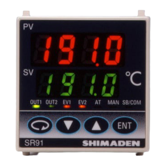
Page 11: Names And Functions Of Parts On Front Panel
4. Names and Functions of Parts on Front Panel Measured value (PV) display Target set value (SV) display OUT1 OUT2 SB/COM Action display lamps Operating keys SR91 Name Function Measured value (PV) Present measured value (PV) is displayed on the screen group 0, basic screen and output display: display screens (OUT1 and OUT2). -
Page 12: Explanation Of Screens And Setting
5. Explanation of Screens and Setting 5-1. Parameter Flow Outline of Parameter Flow displayed below. Set parameter according to the explanation of each setting screen. NOTE: Four kinds of frame lines signify the following: Screens regularly shown Screens which may or may not be shown by key operation and depending on control action modes (PID other means... -
Page 13: Display Upon Power-On
5-2. Display upon Power-ON When power is applied, initial screens upon power-ON are displayed successively, each for about 1 second. Then the basic screen is displayed. Name of series ( Input type ( : Thermocouple, : R.T.D., : Voltage (mV), : Voltage (V), : Current (mA)) Indicates control output 1. -
Page 14: How To Change Set Values (Data)
(4) How to change set values (data) To change data on a screen, use the key, and register the changed data by pressing the key. 5-4. Auto Return Function If no key is operated for 3 minutes or longer on a screen (except the 0-1 output 1 monitor screen, 0-2 output 2 monitor screen and 1-27 heater current monitor screen), the screen automatically changes to the 0-0 basic screen of the mode 0 screen group. -
Page 15: At (Auto Tuning)
2) Supplemtary explanation of using the manual control output Monitor screens (OUT1 and OUT2) and automatic/manual output: When automatic output is changed to manual, balanceless/bumpless transfer is provided, and the value of output right before the change is displayed. Changing from manual to auto also provides balanceless/bumpless transfer, but not if the PV value is outside the proportional band. -
Page 16: Standby Mode (Stby)
4) Automatic stop conditions of AT If any of the following occur while AT is in execution, AT will be released: The output value has been at 0% or 100% continuously for 200 minutes. Scaleover of PV value The control execution is changed to standby. 5) AT action in two-output specification AT works as follows up to the RA or DA characteristic in the two-output specifications: RA characteristic: PID constants are common to OUT1 and OUT2. -
Page 17: Setting Of Event Set Value
(5) Setting of event set value Before a value is set, an event type should be set as described in the following paragraph, "1) Event type setting". When an event type code is changed, however, all the set values (data) concerning the event are initialized. 1) Event type (alarm type) setting Call the 1-21 event 1 type code setting screen (or the 1-24 for event 2) of the screen group 1 and select one from the type codes Hd, Ld, od, id, HA and LA by pressing the... -
Page 18: Explanation Of Screen Group And Setting
6. Explanation of Screen Group and Setting Initial screen To the Basic screen 3 seconds 1-57 1-2 screen To the PV display at standby Initial value: Lower limit value of measuring range setting screen Setting range: Within measuring range (within SV limiter) A measured value (PV) is displayed on the top and the bottom is Pressing the key for 3 seconds continuously on the basic... -
Page 19: Output 1 Proportional Band Setting
(2) Setting of output Output 1 propotional band (P) setting screen 1-10 Output 1 proportional cycle time setting screen Initial value: 3.0% Contact output: 30 seconds Initial value: Setting range: OFF, 0.1 – 999.9% SSR drive voltage output: 3 seconds Setting range: 1 –... - Page 20 (3) Setting of events (4) Setting of Heater break/loop alarm Please refer to section 8-1, 8-2 and 8-3. Heater current monitor screen 1-27 Event at STBY setting screen 1-20 This screen is displayed when the optional heater break/loop alarm function is added and used to monitor heater current. Initial value: OFF (There is no item to be set on this screen.) Setting range: OFF, ON...
- Page 21 Communication data format setting screen Initial value: Setting range: 7E1, 7E2, 7N1, 7N2, 8E1, 8E2, 8N1, 8N2 A communication data format is set. Code Data length Parity Stop bit Shimaden ASCII RTU 7 bits Even 1 bit 7 bits Even...
- Page 22 (8) Setting of control output characteristic (13) Setting of measuring range code Control output characteristic setting screen Measuring range code setting screen 1-45 1-51 Initial value: Initial value: Universal 05, voltage 86, current 92 Setting range: Select from the Table of Measuring Range Codes Setting range: in Section 7.
-
Page 23: Table Of Measuring Range Codes
7. Table of Measuring Range Codes Select a measuring range from the following table. A change of the code will initialize all date related to the measuring range. Input type Code Measuring range (°C) Measuring range (°F) 1800 3300 1700 3100 1700 3100... -
Page 24: Explanation Of Functions
8. Explanation of Functions All the details are mentioned here except the explanation of 5-5. Procedure of Setting in Screen Group 0. 8-1. Events (1) Deviation alarm An alarm action point is set by a deviation from target set value (SV). For example, when the target set value is 20°C, +10°C should be set for higher limit deviation alarm in order to put an alarm in action at 30°C and higher. -
Page 25: Alarm Action Diagrams
8-3. Alarm Action Diagrams The followings are diagrams showing alarm actions that can be selected as event 1 and event 2. : SV value : Alarm action point : Lower limit deviation alarm : Higher limit deviation alarm Action ON Action ON Hysteresis Hysteresis... -
Page 26: Proportional Cycle Time
8-6. Proportional Cycle Time It should be within a range from 1 to 120 seconds in the case of contact output or SSR drive voltage output. Proportional cycle time is ON time + OFF time. The following diagram shows the correlation between proportional cycle time and control output. In case the output is 20 %. -
Page 27: Standby (Stby)
(2) Standby (STBY) This can be set by specifying STBY (standby) at DI mode. If STBY is selected, the 0-3 STBY action setting screen is for monitoring only, and the setting cannot be performed. When DI input signal is OFF: The controller is under control. -
Page 28: Maintenance And Troubleshooting
9. Maintenance and Troubleshooting 9-1. Cause of Trouble and Troubleshooting Problem Cause Remedy 1. Error code is displayed. 1. Refer to "9-2. Error Codes, Causes and Remedies." 1. Refer to "9-2. Error Codes, Causes and Remedies." 2. Displayed PV value seems to 1. -
Page 29: Record Of Parameter Setting
10. Record of Parameter Setting For convenience sake, recording set values and selected items is recommended. The initial values are of Code 05 (K) Screen No. Initial value Record Parameter (Item)/screen display Setting/Selection Basic screen Output 1 monitor Output 2 monitor STBY action STBY. -
Page 30: Specifications
11. Specifications Display Digital display: Measured value (PV)/7 segments red LED Output action mode: MAN (manual), AUTO (automation) 4 digits / STBY (standby) Target set value (SV)/7 segments green Event at STBY: ON/OFF LED 4 digits Type of control/rating: Contact/1 a 240V AC 2A (resistive load) Display accuracy: ±(0.3%FS + 1 digit) - Page 31 SV value in execution is changed. Communication memory mode: EEP/RAM/r_E 4 Control mode without standby action (No Communication protocol (1): Shimaden protocol alarm is output at the time of abnormal input). Data format: 7E1, 7E2, 7N1, 7N2, 8E1, 8E2, 8N1, 8N2 Output type/rating: Contact (1a ×...
- Page 32 External dimensions: SR91: H48×W48×D111 (Panel depth: 100) mm SR92: H72×W72×D111 (Panel depth: 100) mm SR93: H96×W96×D111 (Panel depth: 100) mm SR94: H96×W48×D111 (Panel depth: 100) mm Mounting: Push-in panel (one-touch mount) Panel thickness: 1.0 to 4.0 mm Panel cutout: SR91: H45×W45 mm SR92: H68×W68 mm SR93: H92×W92 mm SR94: H92×W45 mm...
Need help?
Do you have a question about the SR90 Series and is the answer not in the manual?
Questions and answers