Shimaden SR90 Series Instruction Manual
Digital controller
Hide thumbs
Also See for SR90 Series:
- Instruction manual (24 pages) ,
- Instruction manual (16 pages) ,
- Instruction manual (32 pages)
Table of Contents
Advertisement
Quick Links
Please check that the delivered product is the correct item you ordered.
Please do not begin operating this product before you read this instruction manual
Notice:
Please ensure that this instruction manual is given to the final user of the instrument.
Preface: This instruction manual is meant for those who will be involved in the wiring, installation, operation and routine
maintenance of the SR90 series (SR91, SR92, SR93 and SR94). It describes matters to be attended to in handling
the SR90 series, how to install it, its wiring, its functions and operating procedures. Keep this manual at the work
site while handling the instrument and follow the guidance provided herein
1. Safety Rules................................................................................2
2. Introduction................................................................................ 3
2-1. Check before Use..................................................................3
2-2. Handling Instruction.............................................................4
3. Installation and Wiring.......................................................... 4~7
3-1. Installation Site.....................................................................4
3-2. Mounting.............................................................................. 4
3-3. External Dimensions and Panel Cutout............................... 5
3-4. Wiring.................................................................................. 6
3-5. Terminal Layout................................................................... 7
3-6. Terminal Arrangement Table............................................... 7
4. Names and Functions of Parts on Front Panel........................... 8
5. Explanation of Screens and Setting.................................... 9~18
5-1. Parameter Flow.................................................................... 9
5-2. Display upon Power-ON.................................................... 10
5-3. How to Change Screens..................................................... 10
(1) How to Change Screens in Screen Group 0....................... 10
(4) How to Change Set Values (Data)......................................10
5-4. Before Starting Up..............................................................11
(1) Checking of Wiring............................................................ 11
(2) Application of Operating Power.........................................11
(3) Setting of Measuring Range............................................... 11
(4) Setting of Control............................................................... 11
(5) Setting of Control Output Characteristics.......................... 11
(6) Setting of Event Type.........................................................11
(7) Setting of Analog Output....................................................11
(8) Note on Initialization Following Data Change...................11
5-5. Procedure of Setting in Screen Group 0............................. 11
(1) Setting of Target Set Value................................................ 11
(2) Manual Setting of Control Output......................................11
(3) AT (Auto Tuning)...............................................................12
(4) Setting of Event Set Value................................................. 12
(5) Set Value Bias.................................................................... 13
5-6. Explanation of Screen Group 0 and Setting...................... 14
SR90 Series
(SR91, SR92, SR93, SR94)
Digital Controller
Instruction Manual
Thank you for purchasing a Shimaden product.
thoroughly and understand its contents.
Contents
5-7. Explanation of Screen Group 1 and Setting................. 14~18
(1) Setting of Key lock.......................................................... 14
(2) Setting of Output...............................................................15
(3) Setting of Event................................................................ 16
(4) Heater Current Monitor Screen.........................................16
(5) Setting of Heater Break/Loop Alarm................................16
(6) Setting of Analog Output Type.........................................16
(7) Setting of Communication................................................17
(8) Setting of Control Output Characteristic.......................... 17
(9) Setting of Soft Start Time.................................................17
(10) Setting of SV Limiter........................................................17
(11) Setting of PV Bias Value..................................................18
(12) Setting of PV Filter Time................................................. 18
(13) Setting of Measuring Range Code....................................18
(14) Setting of Temperature Unit............................................. 18
(15) Setting of Input Scaling.................................................... 18
5-8. Table of Measuring Range Codes...................................... 18
6. Explanation of Functions....................................................19~20
6-1. Events................................................................................19
6-2. Setting of Event Standby Action...................................... 19
6-3. Alarm Actions Diagrams.................................................. 19
6-4. P.I.D..................................................................................19
6-5. Manual Reset.................................................................... 20
6-6. Lower Limit and Higher Limit Setting Limiters.............. 20
6-7. Proportional Cycling Time............................................... 20
6-8. Auto Return Function....................................................... 20
6-9. Control Output Characteristics......................................... 20
6-10. Soft Start........................................................................... 20
7. Maintenance and Troubleshooting.................................... 21~22
Attended to........................................................................21
7-2. Causes of Trouble and Troubleshooting...........................21
7-3. Error Codes, Causes and Remedies..................................22
8. Record of Parameter Setting.................................................... 23
9. Specifications..................................................................... 24~25
- 1 -
SR90F-1AE
Dec. 2001
Advertisement
Table of Contents

Related Manuals for Shimaden SR90 Series


Summary of Contents for Shimaden SR90 Series
-
Page 1: Table Of Contents
SR90 series (SR91, SR92, SR93 and SR94). It describes matters to be attended to in handling the SR90 series, how to install it, its wiring, its functions and operating procedures. Keep this manual at the work site while handling the instrument and follow the guidance provided herein Contents 1. -
Page 2: Safety Rules
Make sure to ground it properly. CAUTION WARNING • The SR90 series is designed for controlling temperature, The alert mark on the plate affixed to the instrument: humidity and other physical quantities of general industrial On the terminal nameplate affixed to the case of this equipment. -
Page 3: Introduction
Check the model codes affixed to the case of the product to ascertain if the respective codes designate what was specified when you ordered it, referring to the following code table: SR90 series is based on 3 types of selectable codes SR91 SR92 SR93 and SR94. -
Page 4: Handling Instruction
As the instrument is provided with pawls for fixing, just press it firmly from the front of the panel. The SR90 series instrument is designed in a panel-mounting mode. Never use it without mounting on the panel. - 4 -... -
Page 5: External Dimensions And Panel Cutout
3-3. External Dimensions and Panel Cutout SR91 Panel cutout drawing (48 × N−3) +0.6 ˚C In the case of installation without leaving space OUT1 OUT2 SB/COM between instruments N=The number of instruments Unit: mm SR91 SR92 Panel cutout drawing 100 or more +0.7 OUT1 OUT2... -
Page 6: Wiring
Insert a load line through the hole of the noise filter (No polarity) meant for the controller. With this wire, connect the secondary side terminal of CT to the CT input terminal of the SR90 series controller. Heater (load) wiring - 6 -... -
Page 7: Terminal Layout
3-5. Terminal Layout (Follow the terminal layout and terminal arrangement table shown below in your wiring operation.) SR91 OUTPUT2 4-20mA 24VDC 100-240VAC~ 0-10V /24VAC~ A-output 50/60Hz 11VA 30mA 12V 50/60Hz 7VA − − − 2A 240V RS-485 OUTPUT1 CT/SB − −... -
Page 8: Names And Functions Of Parts On Front Panel
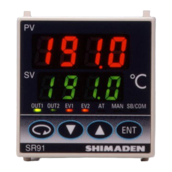
4. Names and Functions of Parts on Front Panel Measured value (PV) display Target set value (SV) display ˚C OUT1 OUT2 SB/COM Action display lamps 4 Operating keys SR91 Name Function Measured value (PV) display: (1) Present measured value (PV) is displayed on the screen group 0, basic screen and output display screens (OUT1 and OUT2). -
Page 9: Explanation Of Screens And Setting
5. Explanation of Screens and Setting 5-1. Parameter Flow (Outline of Parameter Flow displayed below. Set parameter according to the explanation of each setting screen) NOTE: Four kinds of frame lines signify the following: Screens regularly shown Screens which may or may not be shown by key operation and depending on control action modes (PID other means... -
Page 10: Display Upon Power-On
5-2. Display upon Power-ON When power is applied, initial screens upon power-ON are displayed successively, each for about 1 second. Then the basic screen is displayed. Name of series ( Input type ( : Thermocouple, : R.T.D., : Voltage (mV), : Voltage (V), : Current (mA)) Indicates control output 1. -
Page 11: Before Starting Up
5-4. Before Starting Up To begin with, check the wiring and set the items listed below by the setting methods of the screen groups. (Factory-set items and items already set by equipment manufacturers need not be set here.) (1) Checking of wiring: Check that the wiring to connected terminals is carried out properly. Erroneous wiring will result in burnout. -
Page 12: At (Auto Tuning)
2) Supplemtary explanation of using the manual adjustment output Monitor screens (OUT1 and OUT2) and automatic/manual output: When automatic output is changed to manual, output is put in a balanceless/bumpless action and the value of output right before the change is displayed. Changing from manual to auto also causes bumpless action but not if the PV value is outside the proportional band. -
Page 13: Set Value Bias
0-4 Event 1 set value screen Key, E N T Decimal point flashes Decimal point stops flashing, registration Decimal point flashes, changeable 3) Changing the event value To change the value, pressing the or the key causes the decimal point to flash and the value will change. Press the key to set your aimed value, the decimal points will stop flashing. -
Page 14: Explanation Of Screen Group 0 And Setting
5-6. Explanation of Screen Group 0 and Setting 5-7. Explanation of Screen Group 1 and Setting To the 1-2 screen Screen Group 0 Screen Group 1 Key operation: Key operation: key is used to proceed to the next screen. The key and key is used to proceed to the next screen. -
Page 15: Setting Of Output
(2) Setting of output Output 1 propotional band (P) setting screen 1-10 Output 1 proportional cycling time setting screen Initial value: 3.0% Initial value: Contact output: 30 seconds Setting range: OFF, 0.1 ~ 999.9% SSR drive voltage output: 3 seconds Setting range: 1 ~ 120 seconds. -
Page 16: Setting Of Event
(3) Setting of events (4) Heater current monitor screen Please refer to section 6-1, 6-2 and 6-3. 1-26 Heater current monitor screen Event 1 type code setting screen 1-20 This screen is displayed when the optional heater break/loop alarm function is added and used to monitor heater current. (There is no Initial value: Hd item to be set on this screen.) Setting range: OFF, Hd, Ld, od, id, HA, LA, So, Hb... -
Page 17: Setting Of Communication
1-33 Analog output scaling higher limit setting screen 1-39 Communication speed setting screen Initial value: 800.0 (The higher limit value of setting range for Initial value: 1200 PV and SV and 100.0 for OUT1 and OUT2.) Setting range: 1200, 2400, 4800, 9600, 19200 bps Setting range: Within measuring range when PV or SV is A communication speed is set but 19200 bps is displayed as selected 0.0 ~ 100.0% when OUT1 or OUT2 is... -
Page 18: Setting Of Pv Bias Value
(11) Setting of PV bias value 5-8. Table of measuring range codes Select a measuring range from the following table. PV bias value setting screen 1-46 A change of the code will initialize all date related to the Initial value: 0 unit measuring range. -
Page 19: Explanation Of Functions
(All the details sre mentioned here except the explanation of 5-5. Procedure of setting 6. Explanation of Functions screen group 0) 6-1. Events 1) Deviation Alarm An alarm action point is set by a deviation from target set value (SV). For example, when the target set value is 20˚C, +10˚C should be set for higher limit deviation alarm in order to put an alarm in action at 30˚C and higher. -
Page 20: Manual Reset
6-5. Manual Reset In PID action, an offset is corrected automatically by I, i.e., integration. When OFF is set for I, correction is not carried out and so output should be increased or decreased manually. This method is called manual reset. 6-6. -
Page 21: Maintenance And Troubleshooting
7. Maintenance and Troubleshooting 7-1. Procedure of Maintenance Replacement and Matters to Be Attended to (Steps for replacing defective items) Confirmation of Model Code: Check the model code of the component part in trouble. (Open the control box, and you can find an appropriate code in the model label affixed to the instrument case.) Inquiry on Input Data: Ask the manufacturer if input data (control date of external operation, event output, set value of position, etc. -
Page 22: Error Codes, Causes And Remedies
7-3. Error Codes, Causes and Remedies (1) Input measured value problems Screen display Problem Cause Remedy Higher limit side scaleover A break of thermocouple Check thermocouple input wiring for a input wiring possible break. (HHHH) A break of R.T.D. input Check R.T.D. -
Page 23: Record Of Parameter Setting
(For convenience sake, recording set values and selected items is recommended.) 8. Record of Parameter Setting The initial values are of Code 05 (K). Screen No. Parameter (Item)/screen display Initial value Setting/Selection Record Basic screen Output 1 monitor Output 2 monitor AT action Event 1 set value setting E1Hd. -
Page 24: Specifications
9. Specifications RA (reverse characteristic): Heating action (OUT1) Display and cooling action (OUT2) Digital display: Measured value (PV)/7 segments red LED DA (direct characteristic): 2-stage heating action 4 digits Type of control/rating: Contact/1 a 240V AC 2A (resistive load) Target set value (SV)/7 segments green 1.2A (inductive load) LED 4 digits (Common to Output 1 and 2): SSR drive voltage/12V±1.5V DC... - Page 25 Communication delay time: 1~100 (× 0.512 msec) SR93: H92 × W92 mm Communication code: ASCII code SR94: H92 × W45 mm Communication protocol: Shimaden's standard protocol Number of connectable instruments: Weight: SR91: Approximately 170 g RS-232 1 SR92: Approximately 280 g...
- Page 26 M E M O The contents of this manual are subject to change without notice. Temperature and Humidity Control Specialists Head Office: 2-30-10 Kitamachi, Nerima-Ku, Tokyo 179-0081 Japan Phone: +81-3-3931-7891 Fax: +81-3-3931-3089 E-MAIL: exp-dept@shimaden.co.jp URL: http://www.shimaden.co.jp PRINTED IN JAPAN - 26 -...
Need help?
Do you have a question about the SR90 Series and is the answer not in the manual?
Questions and answers