
Related Manuals for HySecurity StrongArm 20


Summarization of Contents
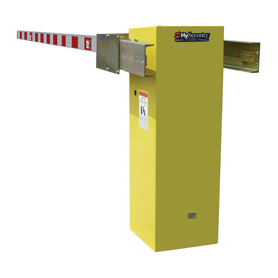
StrongArm Components
StrongArm Pump Pack Components
Details the hydraulic pump system components, including motors, contactors, valves, and reservoir.
Important Safety Instructions
Proper Grounding and Breather Cap Installation
Provides instructions for installing the earth ground rod and replacing the shipping vent plug with a breather cap.
Manual Release: Manual Bypass Valve
Explains the procedure for manually releasing the gate arm in case of power failure or for maintenance.
Installation
Installation Preparation Checklist
A checklist of essential steps and considerations before beginning the gate operator installation.
Electrical power Connection
Details on connecting the primary AC power to the control box and required electrical codes.
Power Connection for Two Part Battery Operators
Instructions for routing AC power to the DC power supply enclosure for two-part operators.
Replace the Vent Plug!
Instructions to remove the shipping vent plug and replace it with the breather cap.
Configuring the Smart Touch Controller
Guidance on configuring the Smart Touch Controller before gate operation.
Attaching Barrier Arms to the Operator
Steps for securely bolting the barrier arm(s) to the operator, including counterweight details.
Basic Testing
Procedures for testing the operator's smooth movement and limit switch function.
Install Accessory Items
Instructions for connecting accessory devices like vehicle detectors and button stations.
Install Warning Signs And Safety Information Labels
Guidance on installing safety warning signs and labels as required by regulations.
Power
Installing the Earth Ground
Details on installing a separate earth ground rod for lightning protection and electrical safety.
Site Considerations
Key site preparation points for permanent gate operator installation, including wiring and power.
Wiring AC Power
Instructions for connecting AC power, including in-rush current and wire sizing recommendations.
Turning the Power Switch ON
Procedure for turning on the AC power and verifying the Smart Touch Controller status.
Wire Sizing and Runs
Guidelines for selecting appropriate wire sizes to prevent voltage loss and ensure performance.
Low Voltage Control Wiring
Maximum distances for low voltage control wiring based on wire size.
StrongArm Wiring Charts (Incoming Power)
Charts detailing wire size and maximum distance for various horsepower and voltage ratings.
Control Transformer Connections (Non-UPS)
Instructions for connecting AC input power to the control transformer.
Gate Operator Connections (Modular Unit)
Details on connecting conduit for hydraulic hoses and electrical wiring for modular units.
DC Power Supply (UPS) Connections
Information on connecting primary AC input power to the DC Power Supply unit.
AC Power Supply with HyInverter AC
Details on gate operators equipped with AC Power Supply and HyInverter AC options.
Initial Setup
Smart Touch Controller: Menu Mode Navigation Buttons
Explains how to navigate the Smart Touch Controller keypad in Menu Mode to set initial prompts.
Leveling and Balancing Arm
Arm Leveling
Steps to adjust the gate arm height using the threaded eyebolt at the base of the hydraulic cylinder.
Balance
Procedure to verify the operating weight of the arm is within the proper range for correct adjustments.
StrongArm CounterWeights Installation
Arm Length and Counterweights
Table detailing counterweight requirements based on arm length for optimal performance.
Valve Adjustments
Adjust Pressure Relief Valve
Procedure for adjusting the pressure relief valve to set maximum system hydraulic pressure.
Adjusting Brake Valve
Steps for adjusting brake valves to ensure smooth gate operation and stopping.
Limit Switch Adjustments
Guidance on adjusting limit switches for smooth stopping of the arm at travel ends.
Emergency Override
Manual Bypass Valve
Instructions for using the bypass valve to manually operate the gate arm.
Cycle Test the Arm
Procedure for testing the gate arm operation after adjustments.
Entrapment Protection
Assess Your Gate Site.
Design the gate installation to minimize entrapment zones and install the operator.
Install NC sensors.
Instructions for installing non-contact sensors (photo eyes) to prevent arm lowering on people.
Turn Power ON.
Step to turn power on and prepare for initial setup prompts.
Answer Initial Setup Prompts.
Guidance on responding to initial prompts for Usage Class and sensor configuration.
Table 4: HySecurity Gate Operators maintaining Object Detection
Table indicating gate operators with object detection capabilities and their UL 325 compliance.
External Entrapment Protection
Photo Eye Installation Tips
Tips for installing photoelectric sensors, including types and wiring requirements.
PHOTO EYE FUNCTION:
Alignment
Procedure for careful optical alignment of photo eyes for reliable operation and to avoid false triggers.
Notes about retro-reflective systems:
Considerations for retro-reflective photo eye systems regarding installation and performance.
Control Panel Overview
Limit Switches
Description of limit switches that determine the arm's open and close positions.
Backplate of Display and Keypad
Overview of the backplate holding the display and keypad for operator interaction.
Power ON/OFF Switch
Location and function of the main power ON/OFF switch.
Power Module
Details on the power module providing 24VAC and 24VDC terminals.
Transformer
Explanation of the transformer's role in stepping down AC voltage for the operator.
HY-5B Vehicle Detectors
Identification of the HY-5B vehicle detector connection point.
Smart Touch Controller
Overview of the Smart Touch Controller's inputs for peripherals and accessories.
STC Board, Power Supply Board and Display
Smart Touch Controller
Details on the Smart Touch Controller's inputs, relays, and connections.
STC Display & Keypad
Information on the STC display and keypad for programming and diagnostics.
Display & Menu Options
Initial Setup
Steps for initial operator programming after installation and power connection.
Understanding the Display and Keypad
Explanation of the STC display and keypad functions in different operational modes.
Menu Mode and the STC Keypad
Details on using the STC keypad for data entry and menu navigation in Menu Mode.
Menu Mode Navigation
Guide to navigating program menus using the STC keypad buttons.
Run Mode and the STC Keypad
Description of Run Mode displays and how the keypad interacts with the operator status.
Viewing Gate Operator Scrolling Status
How to view operator status displays and configurations that scroll across the display.
Stop the Status Display Scrolling
Instructions on how to stop and resume the operator status display scrolling.
Change the Contrast on 7 Segment Displays
Guidance on adjusting display contrast for 7-segment displays.
Display Power Saving Mode
Explanation of how the display dims to conserve energy and returns to full brightness.
Check the Software Version
Procedure to check the operator's software version and upload updates.
Check Time and Date
Steps to verify and set the operator's date and time zone.
User Menu
Accessing and navigating the User Menu for operator configurations.
User Menu: Table 5
Table detailing User Menu items, settings, tasks, and STC wire connections.
Installer Menu
Installer Menu: Table 6
Table detailing Installer Menu items, settings, tasks, and STC wire connections.
AD 0 AC/DC GATE
Installer menu setting to select the gate operator's power type (AC/DC).
SP 0 SET SPEED
Installer menu item to set the maximum gate speed, applicable to 50VF series operators.
UC 0 USAGE CLASS
Installer menu setting to designate the UL 325 Usage Class for operator functionality.
SH 0 GATE HANDING
Installer menu setting to define gate handing (left or right) for slide gate operators.
BU 0 LOUDEST BUZZER
Installer menu setting to select the audible buzzer frequency for the operator.
FD 0 (OFF) FACTORY DEFAULTS
Installer menu option to restore operator settings to factory defaults.
DG 0 (OFF) DUAL GATE
Installer menu item to establish communication for dual gate configurations.
SG 0 (OFF) SEQUENCED GATE
Installer menu item to establish communication for sequenced gate configurations.
CH 0 (AC) CHARGER TYPE
Installer menu item to designate the charger type for DC powered operators.
FO 0 (DISABLED) FIRE DEPT OPEN
Installer menu setting to enable the Fire Department Open input.
OC 0 (DISABLED) EMERGENCY CLOSE
Installer menu setting to enable the Emergency Close input.
SE 2 IES SENSITIVITY
Installer menu setting to adjust the sensitivity of the inherent entrapment sensor.
SS 0 IES STOP ONLY
Installer menu setting for IES behavior: stop and reverse, or stop only.
LC 0 LEAF DELAY CLOSE
Installer menu setting for leaf delay before closing for primary/secondary operators.
LO 0 LEAF DELAY OPEN
Installer menu setting for leaf delay before opening for primary/secondary operators.
RT 0 (60 SECS) MAXIMUM RUN TIME
Installer menu setting for maximum gate run time.
PO 0 (OFF) PARTIAL OPEN
Installer menu setting to activate the partial open input and set duration.
EC 0 STOP ONLY EYE CLOSE LOGIC
Installer menu setting for photo eye close logic behavior.
EO 0 STOP ONLY EYE OPEN LOGIC
Installer menu setting for photo eye open logic behavior.
GR 0 FULL OPEN GATE EDGE LOGIC
Installer menu setting for gate edge logic behavior.
SR 1 REVERSE 25 REVERSAL LOGIC
Installer menu setting for inherent sensor reversal logic.
S1 0 SENSOR #1 TYPE
Installer menu setting to configure the type of sensor for input S1.
S2 0 SENSOR #2 TYPE
Installer menu setting to configure the type of sensor for input S2.
S3 0 SENSOR #3 TYPE
Installer menu setting to configure the type of sensor for input S3.
PC 0 NO INPUT PHOTO EYE OUTPUT
Installer menu setting for photo eye output type (NO or NC).
GC 0 NO INPUT GATE EDGE OUTPUT
Installer menu setting for gate edge output type (NO or NC).
TC 1 (INTLOCK) TIME CLK/INTLOCK
Installer menu setting to configure terminal 7 for interlock or time clock input.
DT 0 FREE EXIT DISABLE FUNCTION
Installer menu setting to disable the Free Exit Detector or Close Timer function.
OR 1 REVERSE OUTSIDE OBS LOOP
Installer menu setting for Outside Obstruction Loop behavior.
IR 1 REVERSE INSIDE OBS LOOP
Installer menu setting for Inside Obstruction Loop behavior.
CR 0 REVERSE CLD Pause Open
Installer menu setting for behavior when center loop triggers during closure.
CB 0 (OFF) CLD Disable ELD
Installer menu setting to disable the Free Exit Detector (ELD) input.
EB 0 (OFF) ELD Backoff
Installer menu setting for ELD backoff function on vehicle triggers.
DL 1 STANDARD DETECTOR LOGIC
Installer menu setting for detector logic, including anti-tailgate modes.
RL 1 CLOSE LIM RELAY 1 LOGIC
Installer menu setting to configure the function of the User 1 output relay.
R2 6 GATE LOCK RELAY 2 LOGIC
Installer menu setting to configure the function of the User 2 output relay.
R3 1 CLOSE LIM RELAY 3 LOGIC
Installer menu setting for User 3 relay logic, often used for gate LED lighting.
R4 through R11 RELAY LOGIC
Installer menu settings for Hy8Relay module relay logic (Relays 4-11).
TL 2 (45 SECS) OPEN TIME ALERT
Installer menu setting for specifying when the relay activates for open time alerts.
LT 3 (75 SECS) LOITERING ALERT
Installer menu setting for specifying when the relay activates for loitering alerts.
SA 0 (OFF) STC ADDRESS
Installer menu setting to define the system address for network communication.
NE 0 (OFF) NETWORK SETUP
Installer menu setting to enable or disable network addresses.
ID 0 HYINVERTER DIAGNOSTICS
Installer menu setting to control which system diagnostics are displayed.
ELD0 RUN MODE EXIT LOOP SET
Installer menu setting to configure the HY-5B Free Exit loop detector.
ILD0 RUN MODE IND OBS LOOP SET
Installer menu setting to configure the HY-5B Inside Obstruction Loop detector.
OLD0 RUN MODE OUT OBS LOOP SET
Installer menu setting to configure the HY-5B Outside Obstruction Loop detector.
RLD0 RUN MODE RESET LOOP SET
Installer menu setting to configure the HY-5B Shadow/Reset Loop detector.
STC Inputs & Wiring
Make Connections on the Smart Touch Controller
Guide for making peripheral connections to the Smart Touch Controller.
Integrate with Security Systems
Information on integrating gate operators with security systems.
Adapt User Relays for your Gate Site
Guidance on adapting user relays for specific gate site requirements.
Smart Touch Controller Inputs
STC Terminal Inputs
Details on STC terminal inputs and their common uses.
Smart Touch Controller Inputs Chart
A chart listing STC terminal numbers, UL 325/pre-2016 names, wire connections, and uses.
User Relays – Programming Procedure
Programmable User Relays: Table 7
Table detailing programmable user relay settings, performance, description, and wire connections.
Bi-Parting & Dual Gate Systems
Connecting an Interlocked Pair (Dual Gate)
Steps and features for connecting two gate operators as an interlocked pair.
Dual Gate Wiring Connections
Diagram and steps for wiring an interlocked pair of gate operators using DUAL GATE inputs.
Programming a Dual Gate (Interlocked Pair)
Procedure for programming gate operators for Primary/Secondary or Sally Port configurations.
Connecting Sequenced Gates
Sequenced Gate: Configuration #1
Vehicle loop layout for sequenced gates using StrongArm with a slide gate (Configuration 1).
Sequenced Gate: Configuration #2
Vehicle loop layout for sequenced gates using StrongArm with a slide gate (Configuration 2).
Vehicle Detector Installation
Anti-TailGate Mode (Closing Logic)
Setting the anti-tailgate mode using the Detector Logic (DL) installer menu item.
TailGate Alert
Information on using User Relay 11 for tailgating vehicle notifications.
Vehicle Detector Installation: Hy5A and Hy5B
Hy5A Vehicle Detector Module
Overview of the Hy5A detector module and its benefits.
Connecting Hy5A Vehicle Detectors
Step-by-step instructions for installing Hy5A vehicle detector modules.
View Call Level in Real Time
Procedure to view the real-time call level of Hy5A detectors for diagnostics.
Photo Eye Installation
Photo Eyes (Non-Contact) Installation
Planning and integrating photo eyes for entrapment protection and vehicle detection.
Compatibility
Requirements for photoelectric sensors to be UL 325 recognized and compatible with HySecurity operators.
Installation
Steps for installing photo eyes, including locating and mounting receivers and emitters.
Configuration
Configuring photo eyes based on build year and sensor output type (Light/Dark Operate, relay).
Photo Eye Connections: Smart Touch & Smart DC Controllers
Wiring procedures for connecting photo eyes to Smart Touch and Smart DC Controllers.
Photo Eye Function
Explanation of how tripped photo eyes affect gate operation and available optional settings.
Troubleshooting
System Diagnostic Messages
Overview of diagnostic messages (Alert, Fault, Error) and how to clear them.
Typical Problems and Troubleshooting Procedures
Common problems and detailed procedures for identification and resolution.
Troubleshooting Codes: Table 8
Table listing alert/fault/error codes, buzzer sequences, causes, and suggested corrective actions.
General Maintenance
Smart Touch Analyze and Retrieve Tool (S.T.A.R.T.)
Description of the S.T.A.R.T. software for field service activities.
Installing S.T.A.R.T. Software
Step-by-step instructions for downloading and installing the S.T.A.R.T. software.
Software Maintenance
Importance of checking the HySecurity website for the latest software versions.
Electrical Controls
Notes on electrical system maintenance, including cleaning and troubleshooting codes.
Clock Battery Replacement
Procedure for replacing the lithium coin battery that supports the clock.
Mechnical Controls
Stopping the Gate
Explanation of how time delay soft stop and brake valves control gate stopping.
Starting the Gate
Description of the Soft Start system using an Accumulator With Out Gas (AWOG).
Hydraulic System Maintenance
Brake Valve Adjustments
Importance of proper brake valve adjustment for smooth gate operation.
Pressure Relief Valve Adjustments
Procedure for adjusting the pressure relief valve based on gate weight.
Open Valve
Information about the solenoid-operated open valve and its lack of adjustment.
Wiring HySecurity Sensors: Smart Touch
Wiring Tips for SENSOR COM Terminal: Smart Touch
Tips for connecting sensor wiring to the SENSOR COM terminal.
Menu Mode Navigational Tips
Guidance on using the keypad buttons for navigation in Menu Mode.
Specifications
10 StrongArm™ Models
Comparison table of various StrongArm models, detailing specifications like model number, duty cycle, and dimensions.
Need help?
Do you have a question about the StrongArm 20 and is the answer not in the manual?
Questions and answers