Table of Contents
Advertisement
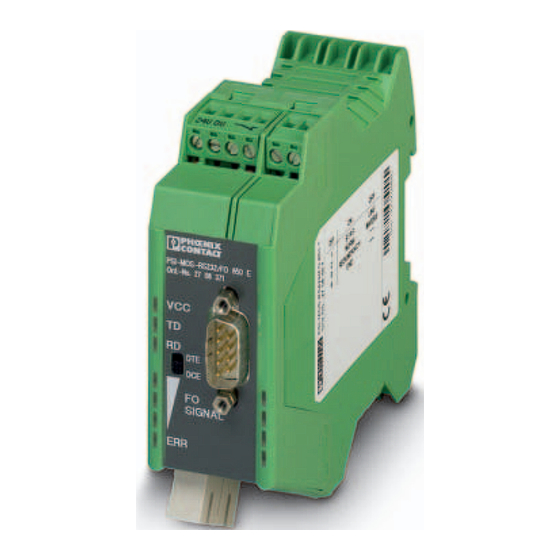
PSI-MOS-RS232/FO 1300 E
Fiber optic converter for RS-232 interfaces
Data sheet
103266_en_02
1
Description
The PSI-MOS-RS232/FO 1300 E device can be used to
convert RS-232 interfaces to fiber optics.
The main advantage of the PSI-MOS fiber optic transmis-
sion system is the electrically isolated connection of de-
vices, which prevents the negative effects of voltage equal-
ization currents and electromagnetic interference on the
data cables. Result: increases the overall availability of the
system and improves flexibility in terms of the design of the
bus topology for point-to-point connections and in star struc-
tures.
Optical star couplers can be combined for a specific appli-
cation by serially connecting up to ten FO modules. Cross-
wiring within a modular star coupler occurs automatically via
the backplane. The system supports progressive transmis-
sion speeds from 4.8 kbps to 115.2 kbps.
WARNING: Explosion hazard when used in potentially explosive areas
This device is a category 3 item of electrical equipment. Follow the instructions provided here during installation
and observe the safety notes.
Make sure you always use the latest documentation.
It can be downloaded at phoenixcontact.net/products.
This data sheet is valid for all products listed on the following page:
© PHOENIX CONTACT 2016-09-12
The devices are also equipped with comprehensive diag-
nostic functions to increase system availability and to sim-
plify startup. The integrated fiber optic diagnostics perma-
nently monitor the optical transmission quality.
Ranges:
–
Up to 45 km with single-mode fiberglass
–
Up to 27 km with multi-mode fiberglass
Connection is via SC duplex connectors.
Advertisement
Table of Contents

Related Manuals for Phoenix Contact PSI-MOS-RS232/FO 660 T


Summary of Contents for Phoenix Contact PSI-MOS-RS232/FO 660 T
-
Page 1: Description
PSI-MOS-RS232/FO 1300 E Fiber optic converter for RS-232 interfaces Data sheet 103266_en_02 © PHOENIX CONTACT 2016-09-12 Description The PSI-MOS-RS232/FO 1300 E device can be used to The devices are also equipped with comprehensive diag- convert RS-232 interfaces to fiber optics. -
Page 2: Table Of Contents
11.1 Connecting the supply voltage ........................15 11.2 Connecting the data cables .......................... 15 11.3 DTE/DCE adjustment ........................... 16 11.4 Wiring the switch contact..........................16 12 Connecting the fiber optic cables (SC duplex) ................17 2 / 17 103266_en_02 PHOENIX CONTACT... -
Page 3: Ordering Data
RS-232 interface to one fiber optic cable 660 nm PSI-MOS-RS232/FO 660 E 2708368 850 nm PSI-MOS-RS232/FO 850 E 2708371 T-couplers with integrated optical diagnostics for converting the RS-232 interface to two fiber optic cables 660 nm PSI-MOS-RS232/FO 660 T... -
Page 4: Technical Data
-20°C ... +60°C Storage/transport -40°C ... +85°C Humidity 30% to 95%, no condensation Dimensions (W x H x D) 35 mm x 105 mm x 99 mm Degree of protection IP20 Weight 190 g, approximately 4 / 17 103266_en_02 PHOENIX CONTACT... - Page 5 EN 61000 corresponds to IEC 61000 Criterion B: Temporary adverse effects on the operating behavior, which the device corrects automatically Criterion A: Normal operating behavior within the specified limits EN 55011 corresponds to CISPR11 5 / 17 103266_en_02 PHOENIX CONTACT...
- Page 6 RTS (7) CTS (8) 24 V 0 V GND Data Data DIN rail connector Figure 1 Block diagram Housing dimensions PSI-MOS-RS232/FO 1300E Ord. No. 27 08 588 SIGNAL Figure 2 Housing dimensions (in mm) 6 / 17 103266_en_02 PHOENIX CONTACT...
-
Page 7: Safety Regulations And Installation Notes
This device is not designed for use in atmospheres with impermissible load, stored incorrectly or if it malfunc- a risk of dust explosions. tions. • Connection to the D-SUB interface is only permitted if the screw connection is tightened. UL notes 7 / 17 103266_en_02 PHOENIX CONTACT... -
Page 8: Supported Network Structures
Cross-wiring for RS-232 data and for the supply voltage is provided automatically by the DIN rail connector (installa- tion accessory, see Page 3). You can connect only one copper-based de- vice to a star coupler. Slaves Star structure 8 / 17 103266_en_02 PHOENIX CONTACT... -
Page 9: Function Elements
Figure 3 Function elements Receiving data at the RS-232 Green (D-SUB 9) copper interface Green Very good FO SIGNAL Green Good Power received at fiber optic port Yellow Critical (see Page 10) Insufficient, broken fiber 9 / 17 103266_en_02 PHOENIX CONTACT... -
Page 10: Definition Of Fiber Optic Diagnostics
FO port A FO port A port by means of full duplex mode. Internal data communi- cation is disabled via the DIN rail connector. Slave 1 Slave 2 Figure 5 Star structure port assignment 10 / 17 103266_en_02 PHOENIX CONTACT... -
Page 11: Configuration
DIP switches 1 to 6 are then freely accessible. No further settings are required in the default setting. • Configure the DIP switches according to the planned application. Figure 7 Setting the DIP switches 11 / 17 103266_en_02 PHOENIX CONTACT... -
Page 12: Connection To Fiber Optic Interfaces From Third-Party Suppliers (Dip 2)
Leave DIP 6 set to "OFF" (single mode) for operation on a single mode fiberglass (9/125 µm) (factory setting). If you are not sure which type of fiberglass is used in your projects, contact your cable supplier. 12 / 17 103266_en_02 PHOENIX CONTACT... -
Page 13: Connection Notes
DIN rails. • End brackets can be mounted on both sides of the de- vice to stop the devices from slipping on the DIN rail (see Page 3 for ordering details). Figure 8 Combined assembly 13 / 17 103266_en_02 PHOENIX CONTACT... -
Page 14: Assembly As An Individual Device In The Control Cabinet (Stand-Alone)
Pull the bottom edge of the module away from the mounting surface. • Pull the module diagonally upwards away from the DIN rail. • If removing a complete star distributor, remove the DIN rail connectors from the DIN rail as well. 14 / 17 103266_en_02 PHOENIX CONTACT... -
Page 15: Cabling Notes
Usually the system power supply is mounted as the first de- vice in a topology. A second power supply unit can be used SIGNAL SIGNAL SIGNAL to create a redundant supply concept. Figure 12 Connecting the data cables 15 / 17 103266_en_02 PHOENIX CONTACT... -
Page 16: Dte/Dce Adjustment
24 V DC 24 V DC 24 V 0 V 24 V 0 V 24 V 0 V 24 V 0 V 24 V 0 V Figure 13 Individual and group message 16 / 17 103266_en_02 PHOENIX CONTACT... -
Page 17: Connecting The Fiber Optic Cables (Sc Duplex)
Due to the integrated optical diagnostics, there is no need to measure the path. PHOENIX CONTACT GmbH & Co. KG • Flachsmarktstraße 8 • 32825 Blomberg • Germany 17 / 17 103266_en_02...
Need help?
Do you have a question about the PSI-MOS-RS232/FO 660 T and is the answer not in the manual?
Questions and answers