Table of Contents
Advertisement
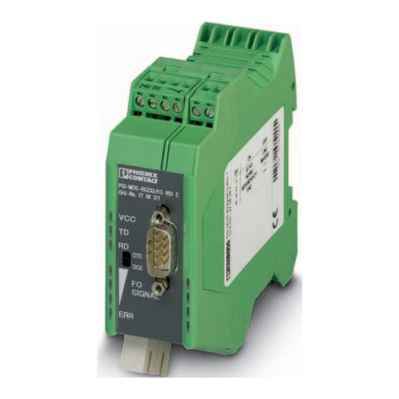
PSI-MOS-RS232/FO 1300 E
Fiber optic converter for RS-232 interfaces
Data sheet
103266_en_02
1
Description
The PSI-MOS-RS232/FO 1300 E device can be used to
convert RS-232 interfaces to fiber optics.
The main advantage of the PSI-MOS fiber optic transmis-
sion system is the electrically isolated connection of de-
vices, which prevents the negative effects of voltage equal-
ization currents and electromagnetic interference on the
data cables. Result: increases the overall availability of the
system and improves flexibility in terms of the design of the
bus topology for point-to-point connections and in star struc-
tures.
Optical star couplers can be combined for a specific appli-
cation by serially connecting up to ten FO modules. Cross-
wiring within a modular star coupler occurs automatically via
the backplane. The system supports progressive transmis-
sion speeds from 4.8 kbps to 115.2 kbps.
WARNING: Explosion hazard when used in potentially explosive areas
This device is a category 3 item of electrical equipment. Follow the instructions provided here during installation
and observe the safety notes.
Make sure you always use the latest documentation.
It can be downloaded at phoenixcontact.net/products.
This data sheet is valid for all products listed on the following page:
© PHOENIX CONTACT 2016-09-12
The devices are also equipped with comprehensive diag-
nostic functions to increase system availability and to sim-
plify startup. The integrated fiber optic diagnostics perma-
nently monitor the optical transmission quality.
Ranges:
–
Up to 45 km with single-mode fiberglass
–
Up to 27 km with multi-mode fiberglass
Connection is via SC duplex connectors.
Advertisement
Table of Contents

Related Manuals for Phoenix Contact PSI-MOS-RS232/FO 660 E


Summarization of Contents
Product Description and Key Features
Device Purpose and Advantages
Explains RS-232 to fiber conversion, electrical isolation, and flexibility in network design.
Transmission Ranges and Connection Type
Details maximum distances for single-mode and multi-mode fiber, and specifies SC duplex connector type.
Explosion Hazard Safety Alert
Provides a warning regarding the use of the device in potentially explosive areas.
Ordering Information
Main FO Converter Part
Specifies the primary FO converter product, its type, and order number for purchasing.
System Accessories and Cables
Lists available accessories like power supplies, end brackets, and fiber optic cables.
Alternative Fiber Optic Converters
Mentions other PSI-MOS models with different distance capabilities and connection types.
Technical Specifications
Interface and RS-232 Data
Covers power supply, current consumption, RS-232 standards, data format, speed, and transmission length.
Optical Interface Performance
Details wavelength, transmission power, receiver sensitivity, and fiber optic lengths with system reserve.
General Device Characteristics
Includes bit distortion, delay, electrical isolation, enclosure material, temperature, dimensions, and weight.
Certifications and EMC Compliance
Lists CE, ATEX, UL approvals and details immunity and noise emission tests according to EMC directives.
Safety and Installation Guidelines
General Installation Best Practices
Covers qualified personnel, device modification limits, IP rating, and environmental operating conditions.
Zone 2 Hazardous Area Installation
Provides specific requirements and warnings for installing in potentially explosive atmospheres (Zone 2).
UL Listing and Requirements
Details related to UL certification, including wire range, terminal torque, and environmental designation.
Supported Network Topologies
Point-to-Point Fiber Link
Describes using two devices to create a direct copper-to-fiber data link.
Star Network Master/Slave Setup
Explains star coupler use, master/slave configurations, and limitations on connected devices.
Function Elements and Status Indicators
Device Component Identification
Identifies physical elements on the device, including LEDs, switches, and connection ports.
Interpreting Status LED Indicators
Explains the meaning and typical states of the VCC, TD, RD, FO SIGNAL, and ERR LEDs.
Fiber Optic Diagnostics Explained
LED Bar Graph for Path Quality
Details how the LED bar graph indicates optical power quality and system reserve status.
Point-to-Point Configuration (DIP 1)
Describes the DIP 1 settings required to establish point-to-point connections.
Star Topology Configuration (DIP 1)
Describes the DIP 1 settings required for star network topology configurations.
Device Configuration Settings
DIP Switch Functionality Overview
Explains the purpose of each DIP switch and their default factory settings.
Point-to-Point Operation Setup (DIP 1)
Details the DIP 1 configuration for operating the device in a point-to-point connection.
Star Network Operation Setup (DIP 1)
Details the DIP 1 configuration for operating the device in a star network topology.
Third-Party Fiber Interface (DIP 2)
Explains how to use DIP 2 to adjust idle settings for compatibility with third-party interfaces.
Transmission Power for Multimode (DIP 6)
Details using DIP 6 to adjust transmission power for multimode fiber optic cables.
Installation and Connection Procedures
Electrical Safety and Grounding
Essential precautions for power supply connections, grounding, and SELV compliance.
Modular Star Coupler Assembly
Step-by-step guide for mounting devices and DIN rail connectors in a star coupler configuration.
Individual Stand-Alone Mounting
Instructions for installing a single device onto a DIN rail in a control cabinet.
Hazardous Area Installation Notes
Specific guidance for installation in areas with dangers of gas and dust explosions.
Device Removal and Dismantling
Procedures for safely detaching the device from the DIN rail mounting.
Wiring and Cabling Guidelines
Connecting Power Supply Voltage
Details for connecting the supply voltage to single devices and within star topologies.
Data Cable and Pinout Connections
Instructions for connecting data cables, including star network specifics and D-SUB pinout.
DTE/DCE Interface Configuration
Explains how to use the DTE/DCE slide switch for adapting to different interface types.
Wiring the Alarm Switch Contact
Details on connecting the floating output for diagnostic signaling and error detection.
Fiber Optic Cable Installation
Fiber Optic Cable Safety and Limits
Warnings about eye safety, contamination, and maximum transmission lengths for fiber optic cables.
SC Duplex Connector Operation
Step-by-step guide for connecting fiber optic cables to SC duplex connectors.
Signal Direction and Wavelength Notes
Guidance on connecting fiber optic channels and compatibility between different wavelength devices.
Need help?
Do you have a question about the PSI-MOS-RS232/FO 660 E and is the answer not in the manual?
Questions and answers